

Page 1
Order toll-free in the U.S.: Call 877-877-BBOX (outside U.S. call 724-746-5500)
FREE technical support 24 hours a day, 7 days a week: Call 724-746-5500 or fax 724-746-0746
Mailing address: Black Box Corporation, 1000 Park Drive, Lawrence, PA 15055-1018
Web site: www.blackbox.com • E-mail: info@blackbox.com
CUSTOMER
SUPPORT
INFORMATION
SEPTEMBER 2005
JHN2046A
JHN2048A
JHN2060A
1. Specifications
Connectors: JHN2046A: (3) F-type;
JHN2048A: (9) F-type;
JHN2060A: (3) F-type
Size: JHN2046A, JHN2048A: 2.9"H x 6.3"W
(7.4 x 16 cm);
JHN2060A: 5.8"H x 6.3"W (14.7 x 16 cm)
Weight: JHN2046A: 0.5 lb. (0.2 kg);
JHN2048A: 0.7 lb. (0.3 kg);
JHN2060A: 2.8 lb. (1.3 kg)
Pure Home Networking Video Combiner,
Splitter, and Booster Modules
2. Overview
The Pure Home Networking Video/Audio Modules
should be installed in one of the Pure Home
Networking Boxes (JHN1014A, JHN1020A, JHN1030A,
or JHN1040A).
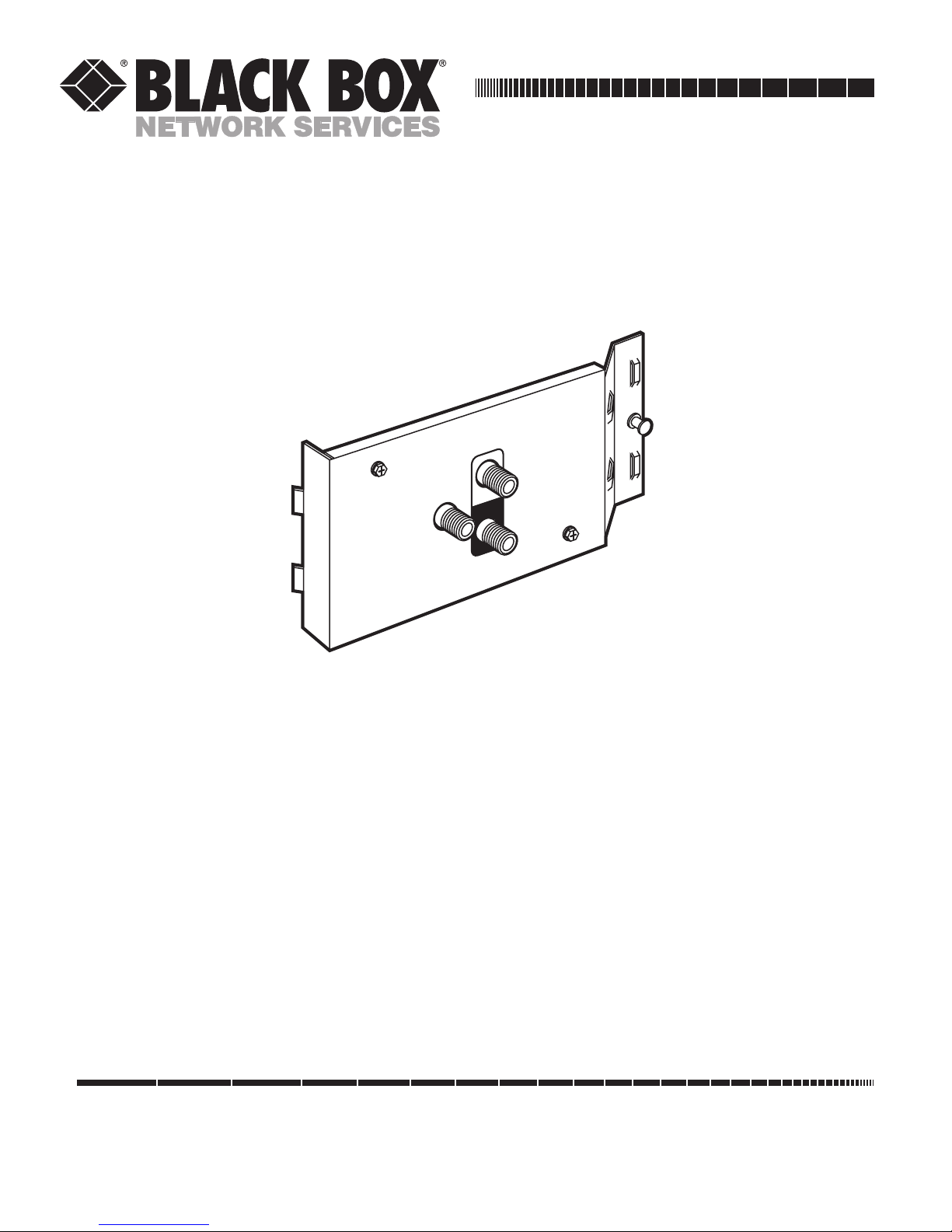
The Pure Home Networking 1 x 2-Port Video Combiner
(Passive) Module (JHN2046A) has three F-type
connectors and operates at frequencies up to 1 GHz.
This module integrates inboard and outbound video
signals and an auxiliary signal such as digital cable. See
Figure 2-1.
Modulated
INPUT
CATV
IN
OUTPUT
Page 2
PURE HOME NETWORKING VIDEO COMBINER, SPLITTER, AND BOOSTER MODULES
2
Figure 2-1. 1 x 2-Port Video Combiner (Passive) Module (JHN2046A).
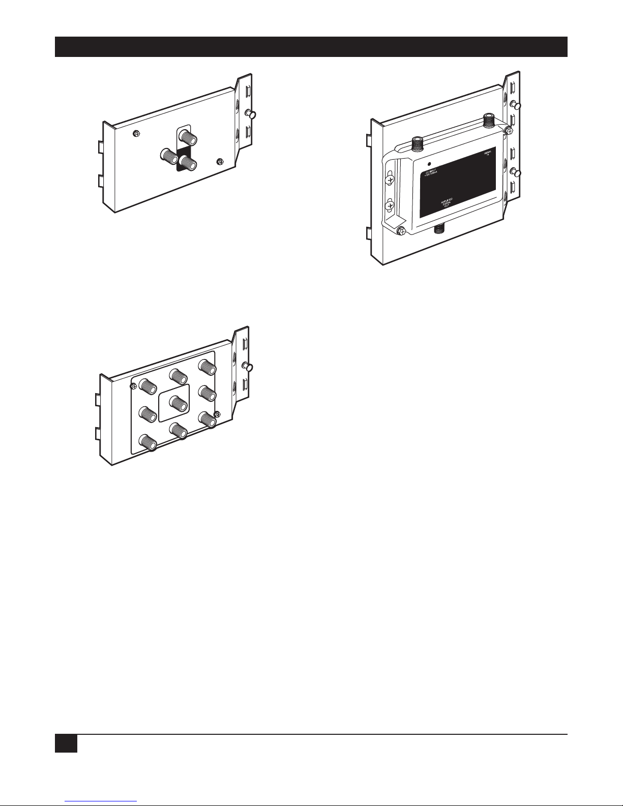
The Pure Home Networking 1 x 8-Port Bidirectional
Video CATV Splitter (Passive) Module’s (JHN2048A)
single input port accepts modulated signals from eight
output video devices (VCRs, TVs, DVDs, etc). It has nine
F-type connectors and supports 1- and 2-GHz signals.
See Figure 2-2.
Figure 2-2. 1 x 8-Port Bidirectional Video CATV
Splitter (Passive) Module (JHN2048A).
The Pure Home Networking Video Signal Booster,
1-Port Module (JHN2060A) amplifies video, digital
cable, and other auxiliary signals up to 25 dB over coax
cable. It has three F-type connectors and includes a
±12 VDC power adapter. See Figure 2-3.
Figure 2-3. Video Signal Booster, 1-Port Module (JHN2060A).
3. Installation
3.1 Tools You’ll Need
• Coaxial wire strippers
• Coaxial connectors
• Coaxial crimpers
• Wire cutters
3.2 Cable Handling Guidelines
• Do not route data cables through the same cable
holes as the AC power cables.
• For safety, separate all data cables from parallel AC
power lines by at least 6 inches (15.2 cm)
whenever possible. Avoid kinking the cable.
• Do not attach cable tie-downs too tightly. The
cable-fastening hardware should not compress
the cable sheath.
• Do not bend the cable sharply. Place the cables
properly in the cable management after passing
them through the holes, since the edges of the
hole can compress or damage the cable sheath.
• When installing an individual module in the Pure
Home Networking Box, place it above or below
the interfacing module (if possible). This will
eliminate excessive cable crossing.
DC
OUT
IN
Modulated
INPUT
CATV
IN
OUTPUT
3
GHz
1
Bandwidth
1
4
6
2
Bi-Directional
Video Module
7
5
8
Page 3

PURE HOME NETWORKING VIDEO COMBINER, SPLITTER, AND BOOSTER MODULES
3
• For your safety, do not use this or any electrical
product near water (unless it is specifically
designed for wet areas). Do not install wiring
during thunder and lightning storms.
• Use caution when handling or installing any
computer, telephone, video, or electrical devices.
3.3 Installing a Module in the Pure Home Networking Box
1. Determine the area for installation.
2. Position the metal tabs on the left side of the
module at a 45-degree angle and slide them into
the rail holes on the Pure Home Networking Box.
3. Insert the metal tabs on the right side of the
module into the rail.
4. Press the button to fasten the module to the Pure
Home Networking Box.
3.4 Removing a Module from the Pure Home Networking Box
1. Press the button and hold it in while pulling the
module from the Pure Home Networking Box.
2. Swing the module out.
3.5 Module Configuration
There are two basic types of video configurations,
single-input and multiple-input. Which one you use
depends on your individual needs.
3.5.1 S
INGLE-INPUT
CONFIGURATION
This configuration simply takes a single inbound
video signal and distributes it out to eight individual
outlets. It’s perfect for cable TV or video distribution.
You’ll need the 1 x 8-Port Bidirectional Video CATV
Splitter (Passive) Module (JHN2048A) only. See
Figure 3-1.
1. Take the incoming video line and connect it to
the center post.
2. Connect the outbound connectors to the
individual outlets. (The module supports up to
eight outlets.)
3. Join the cables neatly together with cable ties
using the cable management channel
anchoring ports.
Figure 3-1. Single-input setup.
3.5.2 MULTIPLE-INPUT CONFIGURATION
This configuration uses multiple modulated input
devices such as DVD players, VCRs, or surveillance
cameras, combining them with cable TV and/or cable
modems, and distributing them to eight individual
outlets.
You will be using a 1 x 2-Port Video Combiner (Passive)
Module (JHN2046A), a 1 x 8-Port Bidirectional Video
CATV Splitter (Passive) Module (JHN2048A), and a
Video Signal Booster, 1-Port Module (JHN2060A). You
will also need a signal modulator (call Tech Support for
details).
For best results, start at the top and work down.
1. Obtain a multi-input modulator (call Tech Support
for details). The modulator allows you to assign
television channels to individual devices.
2. Next, install the 1 x 2-Port Video Combiner
(Passive) Module. Connect the output cable from
the modulator to the modulated input connector
on the combiner.
3. Connect digital or analog cable to the cable TV
post on the video combiner.
CAUTION
Do not plug the cable TV or Internet cable into the
modulated port.
4. Install the Video Signal Booster, 1-Port Module by
connecting a cable from the video combiner
output post to the booster input.
Input
GHz
1
Bandwidth
1
2
Bi-Directional
45
Video Module
6
7
Cable Management
Channel
3
8
To Outlets
#1 - #8
Booster optional
*
Page 4

1000 Park Drive • Lawrence, PA 15055-1018 • 724-746-5500 • Fax 724-746-0746
© Copyright 2005. Black Box Corporation. All rights reserved.
Any trademarks mentioned in this manual are acknowledged to be the property of the trademark owners.
5. Install the 1 x 8-Port Bidirectional Video CATV
Splitter (Passive) Module. Connect a coaxial cable
from the video booster module’s output post to
the bidirectional video module’s center post.
6. Connect posts #1–8 with cables leading to the
room outlets (up to eight outlets).
7. Join the cables neatly together with cable ties using
the cable management channel anchoring points.
Figure 3-2 shows a sample application.
Figure 3-2. Typical multiple-input setup.
OUTPUT
CABLE
IN
MODULATED
INPUT
Bi-Directional
Video Module
1
GHz
Bandwidth
1 GHz
Bandwidth
16273
45
8
To Outlets
#1 - #8
Cable TV
or Internet IN
Video
Combiner
UHB1-M2FB-1
Modulated
Video Signal
Power
IN
Video
Booster
UHB1-M1BV-2
Bi-Directional
Video Module
UHB1-MV1081-1
OUT
INDC
Pure Home
Networking 1 x
2-Port Video
Combiner
(Passive)
Module
(JHN2046A)
Pure Home
Networking
Video Signal
Booster, 1-Port
Module
(JHN2060A)
Pure Home
Networking
1 x 8-Port
Bidirectional
Video CATV
Splitter
(Passive)
Module
(JHN2048A)
 Loading...