


CUSTOMER
SUPPORT
INFORMATION
Order toll-free in the U.S. 24 hours, 7 A.M. Monday to midnight Friday: 877-877-BBOX
FREE technical support, 24 hours a day, 7 days a week: Call 724-746-5500 or fax 724-746-0746
Mail order: Black Box Corporation, 1000 Park Drive, Lawrence, PA 15055-1018
Web site: www.blackbox.com • E-mail: info@blackbox.com
ISDN TA/V
ISDN TA/V
POWER
ISDN OK
SEND
RECEIVE
ANSWER
TERMINAL 1
TERMINAL 2
ON-LINE 1
ON-LINE 2
JANUARY 1995
IS300AE

3
FEDERAL COMMUNICATIONS COMMISSION
RADIO FREQUENCY INTERFERENCE STATEMENT
This equipment generates, uses, and can radiate radio frequency energy and if not
installed and used properly, that is, in strict accordance with the manufacturer’s
instructions, may cause interference to radio communication. It has been tested and
found to comply with the limits for a Class A computing device in accordance with
the specifications in Subpart B of Part 15 of FCC Rules, which are designed to provide
reasonable protection against such interference when the equipment is operated in a
commercial environment. Operation of this equipment in a residential area is likely to
cause interference, in which case the user at his own expense will be required to take
whatever measures may be required to correct the interference.
Changes or modifications not expressly approved by the party responsible for
compliance could void the user’s authority to operate the equipment.
This digital apparatus does not exceed the Class A limits for Radio noise emission from
digital apparatus set out in the Radio Interference Regulation of Industry Canada.
Le présent appareil numérique n’émet pas de bruits radioélectriques dépassant les limites
applicables aux appareils numériques de la classe A prescrites dans le Règlement sur le
brouillage radioélectrique édicté par Industrie Canada.
TRADEMARKS
All applied-for and registered trademarks are the property of their respective owners.
Apple
®
, Macintosh®, and Mac®are registered trademarks of Apple Computer, Inc.
UNIX
®
is a registered trademark of UNIX System Laboratories, Inc.
IBM
®
is a registered trademark of IBM Corporation.
MNP
®
is a registered trademark of Microcom Systems, Inc.
ARC
®
is a registered trademark of DATAPOINT CORPORATION.
Hayes
®
is a registered trademark of Zoom Telephonics, Inc.
VT100
™
is a trademark of Compaq Computer Corporation.
Microsoft
®
is a registered trademark of Microsoft Corporation.
Windows
™
is a trademark of Microsoft Corporation.
FCC/IC STATEMENTS

4
ISDN TA/V
Chapter Page
1. Specifications .............................................................................................9
2. Introduction ...............................................................................................10
2.1 Introducing Your New ISDN Terminal Adaptor.............................10
2.2 Before You Get Started .....................................................................11
2.3 Some Background Information About ISDN..................................13
2.4 A Brief Overview................................................................................14
2.5 Features of the ISDN TA/V..............................................................15
3. Installing ISDN TA/V Using the Intro Software....................................17
3.1 Overview.............................................................................................17
3.1.1 Quick Install ............................................................................17
3.2 About the Intro Program..................................................................17
3.3 Installing Intro Program Files on Your Hard Disk..........................18
3.4 Connecting Your ISDN TA/V ..........................................................18
3.5 Navigating through the Intro Screens .............................................19
3.6 Running Intro from DOS .................................................................19
3.7 Using Intro to Configure the ISDN TA/V.......................................19
4. ISDN TA/V Introduction for Non-Intro Users......................................20
4.1 Preparing for Installation .................................................................20
4.2 Connecting a Computer ...................................................................20
4.3 Connecting an Alternate DTE Device .............................................20
4.4 The CONTROL Port Connection ...................................................20
4.5 Your Communication Software ........................................................21
4.6 The Connecting Cable......................................................................21
4.7 ISDN Service Connection.................................................................21
4.8 Service Number of the Remote Device............................................21
4.9 Communication Settings ..................................................................22
5. Installing the ISDN TA/V Without Intro ...............................................23
5.1 Connecting Your ISDN TA/V ..........................................................23
5.2 Powering On the ISDN TA/V ..........................................................25
5.3 The Front Panel LCD and LEDs ......................................................26
5.4 Macintosh Computer Compatibility Requirements........................27
6. Installing and Configuring Your PC Communication Software ............29
6.1 Selecting Flow Control......................................................................29
6.2 Setting the Data Rate ........................................................................29
6.3 Specifying the Communications Format .........................................30
6.4 Specifying the Terminal Emulation.................................................30
6.5 Specifying the Command Language of the ISDN TA/V ................30
6.6 Configuring the ISDN TA/V DTE and Line Interfaces .................31
Table of Contents

5
Chapter Page
7. Using the ISDN TA/V..........................................................................32
7.1 Dialing Via the Communication Software Menu ............................32
7.2 Monitoring the Call...........................................................................32
7.3 During the Call..................................................................................33
7.4 Logging On to the Remote Computer ............................................33
7.5 Initiating a File Transfer...................................................................33
7.6 Logging Off and Clearing the Call ..................................................33
7.7 Receiving Incoming Calls .................................................................34
7.7.1 Auto-Answering .......................................................................35
7.8 Where to Go From Here...................................................................35
8. Troubleshooting.........................................................................................36
9. Regulatory Information.............................................................................39
Introduction to the Reference Section.........................................................41
10. Principles of Data Communication ........................................................43
10.1 How the ISDN TA/V Works ...........................................................43
10.1.1 Controling the ISDN TA/V ..................................................43
10.1.2 Error Correction ...................................................................44
10.1.3 Data Compression .................................................................44
10.1.4 Flow Control ..........................................................................45
10.1.5 Line Transmission Speed......................................................46
10.1.6 V.110 Rate Adaption .............................................................46
10.2 File Transfer Protocols....................................................................46
10.3 Terminal Emulation........................................................................47
11. Commanding the ISDN TA/V............................................................48
11.1 Via Communication Software Commands ....................................48
11.2 Via Intro Software Menu Selections................................................49
11.3 Using AT Commands......................................................................50
11.4 AT Command Rules........................................................................50
11.4.1 Formatting Command Lines ................................................51
11.4.2 Combining Commands.........................................................52
11.4.3 Waiting for a Response .........................................................52
11.4.4 Editing a Command Line .....................................................53
11.4.5 Repeating a Command Line ................................................53
11.5 Interrupting Data Traffic to Issue AT Commands........................53
12. ISDN TA/V Configurations ...............................................................55
12.1 Factory Configurations ...................................................................55
12.2 Selecting Which Configuration is Active .......................................56
12.3 Viewing Parameter Settings of the Active Configuration .............58
12.4 Creating a User-Defined Configuration ........................................59
12.5 Saving Configurations to the Power-Up Location.........................60
Table of Contents

6
ISDN TA/V
Chapter Page
13. Dialing, Answering, and Clearing Calls Using AT Commands.............61
13.1 Using the D Command...................................................................61
13.2 Using the Number Directory..........................................................62
13.3 Clearing a Call.................................................................................63
13.4 Answering an Incoming Call ..........................................................64
13.5 ISDN TA/V Response Codes..........................................................64
13.5.1 Valid Response Codes ...........................................................65
14. DTE Interface Commands and S-Register Settings.............................68
14.1 Data Transmission Mode ................................................................68
14.2 DTE Electrical Characteristics Conformance................................69
14.3 Default Async Speed........................................................................70
14.4 Setting the Communications Format.............................................70
14.4.1 Number of Data Bits .............................................................70
14.4.2 Parity Bits ...............................................................................71
14.4.3 Number of Stop Bits..............................................................71
14.5 Communications Signaling Requirements....................................71
14.5.1 DTR Control..........................................................................72
14.5.2 DSR Control ..........................................................................72
14.5.3 RTS Control...........................................................................73
14.5.4 CTS Control...........................................................................73
14.5.5 RTS/CTS Delay .....................................................................73
14.5.6 DCD Control..........................................................................74
15. User Commands ................................................................................75
15.1 Selecting AT or V.25bis Dialing Commands .................................75
15.2 AT Escape Sequence Character Key and Response Timeout.......75
15.3 Effect of the BREAK Key on a Terminal’s Keyboard....................76
15.4 Command Character Echo.............................................................77
15.5 Defining the Command Terminator Key ......................................77
15.6 Defining the Backspace Character Key..........................................77
15.7 Defining the Line Feed Character Key ..........................................78
15.8 ISDN TA/V Response (Result) Codes and
Extended Response Codes........................................................78
15.9 V.25bis Command Mode Format ...................................................78
15.10 Responding to AT Commands .....................................................79
15.11 Audible Alert Control ...................................................................79
15.12 Reverting to Power-up Configuration Settings............................80
15.13 Unit Identification Commands ....................................................80

7
Table of Contents
Chapter Page
16. ISDN Line Dialing Characteristics......................................................81
16.1 ISDN Line Transmission Rate ........................................................81
16.2 Enabling and Disabling Auto-Answering.......................................82
16.3 Causes of a Disconnection..............................................................82
17. Error Correction, Flow ControlData Compression, Rate Adaption.........84
17.1 Defining Whether Error Correction and/or
Rate Adaption Will Be Used .....................................................84
17.2 V.42bis Data Compression Characteristics ....................................86
17.3 Flow Control Characteristics (XON/XOFF).................................86
17.4 Buffer Disconnect Timer ................................................................87
18. V.25bis Dialing Commands ................................................................88
18.1 Call Request Commands.................................................................88
18.2 Call Responses.................................................................................89
18.3 Call Answer Commands..................................................................90
18.4 Storing Numbers in Memory (PRN)..............................................90
18.5 Requesting a List of Stored Numbers (RLN)................................91
18.6 List Stored Number Response........................................................91
18.7 Command Responses (Valid and Invalid).....................................91
18.8 Reverting to AT Command ............................................................92
Appendix A — DTE Pin Assignments and Connecting Cables...................93
Appendix B — AT Command Summary ......................................................96
Appendix C — S-Register Summary .............................................................107
Appendix D — ASCII Character Code Chart...............................................109

8
ISDN TA/V
Part I
Getting Started

9
Chapter1: Specifications
ISDN Compliance — Basic Rate ISDN (2B + D) using both channels
simultaneously with automatic channel
aggregation, Q.931, Q.921. V.110 rate adaption.
Compatible with NISDN-1, Euro ISDN, and
other national variants
Synchronisation — Variable RTS/CTS delay
Error Correction — V.42 LAPM
Data Compression — V.42 bis
Speed — X.21 (V.11): synchronous: up to 64000 bps;
asynchronous: up to 115200 bps (with
V.42 bis);
V.24/V.28: Up to 19200 bps;
V.36: Up to 48000 bps
Connectors — (1) RJ-45 female for the ISDN S-bus
(1) Modular phone socket (connector type will vary
depending on which ISDN TA/V you purchase)
(1) DB25 female for your DTE
(1) RJ-11 female CONTROL port, for entering
asynchronous AT commands
Power — 190 to 265 VAC, 47-63 Hz, 0.1A max, 11 watts
Size — 15H x 9W x 27D cm
Weight — 1.3 kg
1. Specifications

10
ISDN TA/V
2.1 Introducing Your New ISDN Terminal Adaptor
Your new ISDN TA/V provides a standalone interface to ISDN for your nonISDN equipment. It provides one S-Bus ISDN Basic Rate connection to a
single serial port, capable of handling both synchronous and asynchronous
data. A separate analogue port is also provided which can support a
connection to any standard analogue telephone network compatible
equipment, working in DTMF (dial tones not pulses) mode.
There are 10 separate models of the ISDN TA/V, with different power and
ISDN line specifications to accommodate the various requirements of
countries throughout the world. These differences have no effect on the
overall performance of any one model, however, so this manual is applicable
to all of them.
2. Introduction

11
2.2 Before You Get Started
2.2.1 A
BOUT THEMANUAL
“Do I have to read all the documentation?” You’ll be glad to know the answer
is no. The ISDN TA/V is designed for use by experienced and novice users,
and the manual is written with both in mind. It’s divided into two parts: Part I,
Getting Started; and Part II, Reference. In fact, there are several ways you can
use the manual to learn about your new ISDN TA/V:
Required Reading:
Your ISDN TA/V has been approved by BABT (the British Approvals Board
for Telecommunications) for connection to British Telecom’s ISDN service
under the approval number of NS/3940/5/P/604019, and it is important
that you make yourself familiar with the conditions of use as described in
Chapter 9 of this manual.
Installing ISDN TA/V Using the Intro Software (Chapter 3.0):
Intro is a DOS-based, full-featured program for installing and configuring
your ISDN TA/V. For most applications, it can be used as a substitute for
much of this manual. Read Chapter 3 to learn how to install and use Intro.
Then skip to Chapters 6 and 7 for information about making and receiving
ISDN calls.
Installing ISDN TA/V Without the Intro Software (Chapters 4-7):
These chapters provide a brief introduction for people who don’t use the
Intro software. You’ll learn how to install the unit, what additional
equipment you’ll need to establish a connection to a remote device, and
finally, how to configure your communication software (not included) so
you can instruct the ISDN TA/V to initiate and receive calls.
In most cases, the ISDN TA/V’s factory-default settings will be sufficient for
your application. And once you read through Chapters 4-7, you’ll be able to
use the Terminal Adaptor to connect to a remote computer via an ISDN
network, and carry out file transfers to and from it.
Part II: The Reference Section:
Part I, Getting Started does not cover any of the ISDN TA/V’s more
sophisticated features, or details about the command language you can use
to alter and customise your ISDN TA/V’s operation. You’ll find that
information in the Reference section of this manual.
Apple Macintosh Users:
Section 5.4 details special cable requirements you’ll need to know.
Chapter 2: Introduction

12
ISDN TA/V
2.2.2 C
ONVENTIONSUSED INTHISMANUAL
Keyed commands that you send to the ISDN TA/V, LCD messages, and
product features such as LED and port names, software titles, and menu
titles all appear in boldface letters, to help you distinguish them from the
descriptive text of this manual.
2.2.3 U
NPACKING
Before you install your ISDN TA/V, it is important that you compare the
contents of the shipping package against the packing list. If any of items listed
are damaged or missing, call your supplier to resolve the matter immediately.
You ISDN TA/V should include:
• (1) ISDN TA/V
• (1) Mains power cord
• (1) 3-metre line cord for connecting to the ISDN2 service
• (1) 2-metre DB9-female-to-DB25-male V.24 DTE cable
• This User’s Manual
• (1) 3.5-inch diskette, containing the Intro software
Save the box and protective packing material in case you need
to store or ship the terminal Adaptor in the future.

13
Chapter 2: Introduction
2.2.4 C
ALLINGYOURSUPPLIER
If you determine that your ISDN TA/V is malfunctioning, do not attempt to alter
or repair the unit. It contains no user-serviceable parts. Contact your supplier.
Before you do, make a record of the history of the problem. Your supplier will
be able to provide more efficient and accurate assistance if you have a
complete description, including:
• The nature and duration of the problem.
• When the problem occurs.
• The components involved in the problem.
• Any particular application that, when used, appears to create the problem
or make it worse.
2.3 Some Background Information About ISDN
ISDN (Integrated Services Digital Network) is a public switched digital
network which enables voice, data communications, video and many other
services, to be transmitted simultaneously over a single pipe consisting of two
64000-bps streams and a 16000-bps control channel.
The two 64000-bps streams are known as the bearer channels (B channels for
short; B1 and B2), with the control channel being referred to as the D
channel.
Your ISDN TA/V is approved for connection to an approved ISDN-2 service,
operating at data rates of 64000 bps, 56000 bps, 48000 bps, 38400 bps, 19200
bps, 14400 bps, 12000 bps, 9600 bps, 7200 bps and 2400 bps. Each of the two
B channels supported on a single ISDN line can be associated with either the
DTE interface or the telephone socket within your ISDN TA/V, and as such
provides you with simultaneously active data and voice channels.
B channel selection is handled automatically by the ISDN TA/V, and is totally
transparent to the user.

14
ISDN TA/V
2.4 A Brief Overview
You connect the ISDN TA/V to your ISDN service line via a rear-mounted
RJ-45 connector, which is fully compliant with ITU standards for the
ISDN S interface. Depending on the nature of the active traffic (data or
voice), this ISDN interface is automatically connected to either the rear
panel mounted 25-pin digital DTE interface, or via the unit’s analogue
circuitry to the telephone handset socket.
The 25-pin female DTE connector is by default configured to conform to
the electrical characteristics of ITU recommendation V.24/V.28 running in
asynchronous data mode, supporting a throughput rate of up to 19200 bps.
Using the AT command language to alter the active configuration, this port
can be configured to operate synchronously conforming to V.24/V.28;
synchronously conforming to ITU X.21 (V.11) at speeds up to 64000 bps
(aggregated channels); asynchronous conforming to ITU X.21 (V.11) at
speeds up to 115200 bps using V.42bis data compression; or
asynchronously/synchronously conforming to ITU V.36 at speeds up to
4800 bps.
A separate CONTROL port is provided for optionally entering AT commands
from an attached asynchronous terminal, and for accessing the management
interface of the ISDN TA/V. When the DTE interface is configured to
operate asynchronously (default configuration setting) the CONTROL port
would not normally be used since all commands can be entered via the DTE.
However, AT commands can only be entered asynchronously and a separate
command port is therefore required when the DTE has been configured to
operate synchronously. The CONTROL port operates at 9600 bps.
Industry standard communication software packages can be used to give
error-free data transfer and control. When installed in your PC, the
communication software is used to command the ISDN TA/V to dial and
accept calls etc. There is a wide variety of these software packages available
from computer dealers and computer user groups, the majority of which are
fully compatible with your ISDN TA/V.
A large number of specialised features such as error correction, data
compression, and rate adaption are supported by your ISDN TA/V. For
details of how and where such facilities should be used, and the configuration
requirements of the ISDN TA/V to enact them, refer to Part II, the reference
section of this manual.

15
Chapter 2: Introduction
2.5 Features of the ISDN TA/V
Your ISDN TA/V is a fully featured, high-speed digital dial-up device which
provides reliable asynchronous and synchronous operation over the ISDN. As
a complement to the high speed data transfer of up to 64000 bps, ITU V.42bis
data compression and ITU V.42 error correction are supported. The data
transfer speed between the DTE interface and your attached computer can
be configured to be as high as 115200 bps.
The ISDN TA/V’s compatibility with a number of dialing methods and
protocols, such as asynchronous AT commands and ITU V.25bis dialing,
allows you to use the unit in a variety of applications and environments, and
to control the ISDN TA/V’s configuration, dialing characteristics and
diagnostic features.
Four factory set configurations, containing the most commonly-used DTE
interface settings, are permanently stored in the Terminal Adaptor’s memory,
providing you with a quick and easy method of configuring the unit to be
compatible with asynchronous and synchronous data environments,
conforming to ITU V.24/V.28, X.21 (V.11) or V.36.
The principal features are:
• Support for digital to digital communication at speeds up to 64000 bps.
• V42bis data compression and V42 error correction via the ISDN sevice.
• V.110 rate adaption techniques.
• Rear-panel phone socket for connecting a PSTN telephone handset
(or other analogue equipment) to the ISDN service.
• Simultaneous support for ISDN-to-ISDN voice and data calls.
• All available DTE and analogue ports have access to either or both ISDN B
channels.
• Asynchronous dial DTE data rates from 300 to 115200 bps.
• Asynchronous AT commands entered via the DTE interface or the
dedicated CONTROL port.
• ISDN TA/V configuration changes via AT commands and the Intro
software program.

16
ISDN TA/V
• Compatibility with the industry-standard AT command set.
• Storage of up to 20 ISDN numbers in directory locations.
• Dialing via AT commands, V.25bis, or via PC by raising DTR
on the PC-to-DTE interface.
• High-speed transmission using asynchronous, synchronous, or UNIX
®
devices over the ISDN.
• Self-testing facility.
• Four factory-set configurations and two user-definable configuration
locations.
• Front-panel LCD and LED displays to inform you of the current status.

17
Chapter 3: Installing ISDN TA/V Using the Intro Program
3.1 Overview
Intro is a DOS-based software program that you load and run from your PC.
It’s designed to help you install and use all of the ISDN TA/V’s features and
facilities. To use Intro, your computer must be IBM®compatible, with a 3.5inch floppy drive, and a graphics card of at least EGA standard.
A DOS mouse driver is not a prerequisite, but it is recommended, since
Intro is easier to use under mouse control than keyboard control.
3.1.1 Q
UICKINSTALL
Insert the Intro diskette into your PC and type:
SETUP<CR>
from the appropriate drive prompt. Follow the on-screen prompts to install
the program files onto your hard disk. Select INSTALLATION from the
program’s main menu options. Instructions for installing and using your
ISDN TA/V will be clearly explained on-screen.
Installation is now complete, with each physical connection having been
tested for you. Using Intro you will now be able to make ISDN TA/V
configuration changes etc.
3.2 About the Intro Program
Initially, Intro familiarizes you with the ISDN TA/V and explains how it
should be connected to a DTE, the ISDN line, and a telephone handset.
Each connection that you make is automatically tested by Intro.
Subsequently the Intro software can be used to alter the ISDN TA/V’s
operating configuration either by you selecting an application, by selecting
specific features, or interactively (as though you had a dumb terminal
connected to the CONTROL port). However, it is important to note that
if you alter the definition of the DTE interface (from its default setting of
V.24/V.28 asynchronous command), Intro will no longer be able to
communicate with the ISDN TA/V.
3. Installing ISDN TA/V
Using the Intro Program

18
ISDN TA/V
3.3 Installing Intro Program Files on Your Hard Disk
To install the Intro files on your hard disk:
1) Insert the program diskette into the floppy drive of your PC, and type the
letter which identifies the floppy drive, followed by a colon and then press
return as shown below:
A:<CR> or B:<CR>
When the DOS prompt alters to indicate that this drive is active, type:
SETUP<CR>
An error message will be displayed if the PC’s graphics card is not able to
support the Intro software, and the installation will be aborted. If this
occurs, move on to Chapter 4 and follow the remainder of this manual.
2) Follow the instructions given on-screen to install the files within the
required directory.
3.4 Connecting Your ISDN TA/V
Once the Intro files are installed on your hard disk, answer YES when the
final screen prompts you with:
Your software is installed. Are you ready to install the ISDN TA/V now?
This automatically initiates the Intro program and displays its base screen
options.
If you answer NO to this screen, refer to Section 3.6 for details of how to
initiate Intro from DOS.
Select INSTALLATION from the base screen and follow the instructions
given. When the ISDN TA/V-to-computer (DTE) connection and the ISDN
TA/V-to-ISDN line connection have been established, they will automatically
be tested by Intro and any errors will be reported to you.

19
Chapter 3: Installing ISDN TA/V Using the Intro Program
3.5 Navigating Through the Intro Screens
When using a mouse to select the appropriate action button, position the
mouse cursor directly over the required action and press the left-hand mouse
button once to select it.
When navigating around the screen using keyboard commands, use the arrow
keys, tab key and shift tab keys to highlight the required option, and the
carriage-return key to action it. Note that the escape key can be used to action
an EXIT button.
3.6 Running Intro from DOS
To run the Intro software from DOS from the root directory of your hard disk
select the sub-directory into which you copied Intro, and type:
INTRO<CR>
3.7 Using Intro to Configure the ISDN TA/V
A powerful function of the Intro software is that it enables you to alter the
ISDN TA/V’s factory-default configuration settings, using simple menu
selections. However, as previously mentioned, the factory-default
configuration will normally be sufficient for most ISDN TA/V users, and may
never need to be altered.
We therefore recommended that this function of the Intro software only be
used by experienced communications device operators, and then only in
conjunction with the reference instructions in Part II of this manual.
If you alter the definition of the DTE interface (from its default setting
of V.24/V.28 asynchronous data), Intro will immediately lose contact with,
and no longer be able to communicate with, the ISDN TA/V. Using the
management interface of the CONTROL port then becomes the easiest
way of commanding the ISDN TA/V. (The Reference section includes
instructions for using this management interface).

20
ISDN TA/V
4.1 Preparing for Installation
In order to install and use your ISDN TA/V, you’ll have to make sure you
have all the proper equipment, cables, and connectors. These requirements
may vary depending on your particular application
4.2 Connecting a Computer
An ISDN TA/V can only receive data from your computer via a serial port
connection. On most IBM or compatible PCs , this would be a D-shell male
connector, V.24 RS-232 serial port, with 9 pins (DB9). Connecting an Apple
®
Macintosh®computer requires an available 9-pin serial port. Most PCs have
only one serial port, which is likely to be labeled COM1.
Many devices other than an ISDN TA/V can be connected to a serial port, for
example a serial printer, mouse or graphics plotter. If your PC has only one
serial port, and this is already supporting an external device, you can swap
between the ISDN TA/V and the other device as required. However, if you
prefer to use both devices without the interruption of plugging and
unplugging cables, ask your PC supplier to install a second serial port.
4.3 Connecting an Alternate DTE Device
This must be equipped with either a V.24/V.28, X.21 (V.11) or V.36 serial
port, for connecting to the DTE interface of the ISDN TA/V.
4.4 The CONTROL Port Connection
Optionally, an asynchronous terminal can be connected to the CONTROL
port of the ISDN TA/V to enable you to pass AT commands to the ISDN
TA/V when using a synchronous transmission format over the DTE interface
link, or to gain access to the unit’s management interface facilities.
The communications format of any device connected to the CONTROL port
must be set to 8N1 (8 data bits, no parity, 1 stop bit), running at
9600 bps.
4. ISDN TA/V Introduction
for Non Intro Users

21
Chapter 4: ISDN TA/V Introduction for Non Intro Users
4.5 Communication Software
When installed in your PC, this is used to command the ISDN TA/V to dial
and accept calls etc. There is a wide variety of these software packages
available from computer dealers and computer user groups, the majority of
which are fully compatible with your ISDN TA/V. For example, a package
such as ‘Terminal’ (a program within the Microsoft®Windows™ 3.0 graphical
environment for PCs) is adequate.
4.6 Connecting Cable
For maximum performance the cable which connects your computer to the
ISDN TA/V DTE interface must support RTS/CTS hardware handshaking for
use with data compression and error correction.
One such cable conforming to the electrical characteristics of the V.24/V.28
interface will have been supplied in your ISDN TA/V package. If for any
reason you have to make up a cable yourself, refer to the cable specifications
in the Appendix. As a general rule: the shorter the cable, the better it is.
Apple Macintosh users should refer to Section 5.4 for details on the
connecting cables they’ll need.
4.7 ISDN Service Connection
You will need a standard ISDN line wall socket to plug your ISDN TA/V’s line
cable into. If one is not available close enough to where you are going to site
your ISDN TA/V, contact your line supplier for assistance.
All connections to the Integrated Services Digital Network are subject to the
rules and regulations of the governing body of the country in which the
connection is made. Chapter 9 of this manual details the statutory
requirements of these governing bodies. It is important that you read these
requirements carefully and ensure your compliance with them.
4.8 Service Number of the Remote Device
In order to connect to a remote device you will obviously need to know the
telephone number of the remote ISDN TA/V.

22
ISDN TA/V
4.9 Communication Settings
To communicate efficiently you will have to configure your communication
software to use the correct word length, parity, and number of stop bits
according to the requirements of the DTE interface or CONTROL port.
Details about how your data is broken into short strings and transmitted
according to the settings of the data format are fully explained in the
Reference section. It’s not important, at this stage, to understand the
significance of the format.
The most popular setting for data format of a service which is connected to
the PSTN is 8 data bits, no parity, 1 stop bit (described as 8N1); although
many public data services use 7 data bits, even parity, 1 stop bit (7E1). You will
normally be advised of the format used by the remote computer or service on
payment of a subscription, or on request if no subscription fee is required.
Setting the communications data format is normally a menu option within
your communication software. Refer to Chapter 6 of this manual for more
information, and your communication software manual for detailed
guidance.
23
Chapter 5: Installing ISDN TA/V Without Using the Intro Program
This chapter should only be followed if you are unable to load and use the
Intro software as described in Chapter 3 It explains how to install your ISDN
TA/V, describes the function of the front panel LEDs, and also details the
special cable requirement for Macintosh computer users.
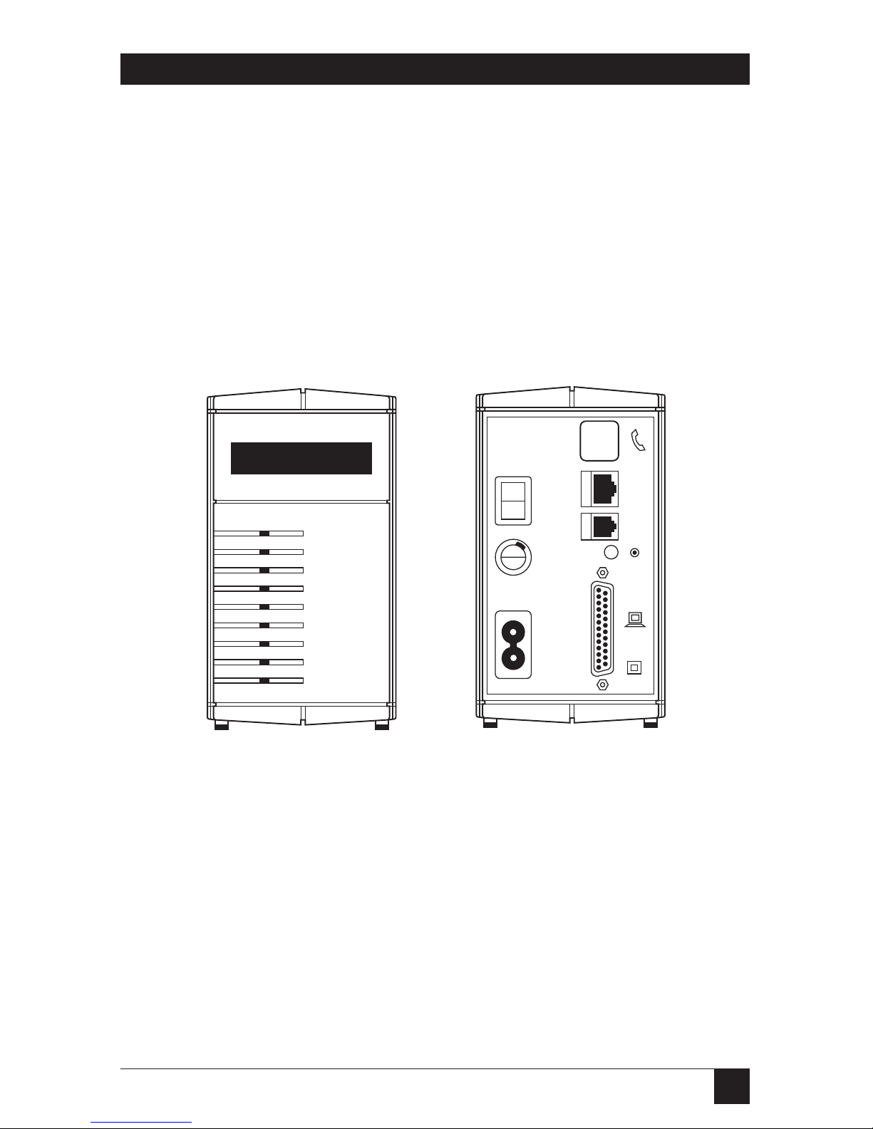
5.1 Connecting Your ISDN TA/V
Use Figure 5.1 and the following steps to connect the ISDN TA/V between
your computer and the ISDN line:
Figure 5.1 Front and Back Views of the ISDN TA/V
1) Ensure that both your computer and the ISDN TA/V are powered off
(The half of the back-panel ON/OFF switch with a circle is depressed).
2) Connect the supplied power lead into the socket marked with the proper
voltage indication on the ISDN TA/V.
3) Plug the other end of the mains lead into a mains socket.
5. Installing the ISDN TA/V Without
Using the Intro Program
POWER
ISDN OK
SEND
RECEIVE
ANSWER
TERMINAL 1
TERMINAL 2
ON-LINE 1
ON-LINE 2
LINE
CONTROL
RESET
DTE
0.5A(T)
250V
~
I
0
220 - 240V
50 - 60 Hz
1A
~

24
ISDN TA/V
4) Insert the male end of the supplied V.24/V.28 DTE connecting cable
into the connector marked DTE on back of the ISDN TA/V, and tighten
the locator screws to secure the cable to Terminal Adaptor.
The cable requirement of the DTE interface when it is configured to
conform to the electrical characteristics of X.21 (V.11) or V.36 are given
in Appendix A. If the interface is going to be configured to conform to
one of these ITU recommendations, a suitable cable should be used in
place of the supplied V.24/V.28 DTE cable. The ISDN TA/V will then
autosense the interface standard if the connecting cable is wired as shown
in Appendix A.
5) Plug the other end of the connecting cable into the serial port on the
back of your computer or other DTE, and tighten the locator screws.
6) Using the ISDN service cable supplied, plug the jack end into the socket
marked LINE on the back of the ISDN TA/V. Note that any ISDN TA/V
can be damaged by lightning. When the possibility of lightning is high,
unplug this connection to the telephone line.
Warning
Interconnection directly or by way of other apparatus, of ports marked
“SAFETY WARNING see instructions for use” with ports marked or not
so marked, may produce hazardous conditions on the network. Advice
should be obtained from a competent engineer before such a connection
is made.
7) Optionally connect an asynchronous VT100™ terminal to the
CONTROL port of the ISDN TA/V. This terminal can then be used to
send AT configuration and dialing commands to the ISDN TA/V, and
also to access the internal management interface.
Note that this terminal connection need not be used if the DTE interface
is configured to accept asynchronous AT commands (default
configuration setting). A PC or terminal connected to the CONTROL
port must be configured to use 8 data bits no parity and 1 stop bit as the
communications format, running at 9600 bps.

25
Chapter 5: Installing ISDN TA/V Without Using the Intro Program
8) Optionally connect a PSTN telephone handset, or any other compatible
analogue equipment, operating in DTMF (tone not pulse) mode to your
ISDN TA/V by connecting the phone’s telephone-line plug into the
socket marked with a handset symbol on the back of the ISDN TA/V.
This port is in effect an analogue to digital converter which allows you to
use your conventional PSTN telephone on an ISDN line.
It is capable of supporting ringing current and call-progress tones, and
will support analogue devices to a maximum of REN=1. Providing one of
the two 64000-bps ISDN channels is not being used by the DTE interface,
it is available for you to make voice calls over the ISDN via this analogue
port.
Incoming ISDN traffic carries a voice/data identifier which enables the
ISDN TA/V to automatically direct incoming voice calls to the handset
port, and incoming data calls to the DTE interface.
9) Plug the unattached end of the supplied line cable into the ISDN wall
socket.
5.2 Powering ON the ISDN TA/V
Having carefully followed the instructions for connecting your ISDN TA/V,
swith on power to the unit by pressing the half of the back-panel ON/OFF
switch marked with a line. Then switch on power to your computer.
Nine LED indicators on the ISDN TA/V’s front panel are used in conjunction
with the LCD display to report the unit’s current status.
When the ISDN TA/V is initially powered-on it initiates a self-test, which is
shown by the LCD reporting
Self Test
followed shortly afterwards by
Passed or Failed
If a self-test failure is reported, or the POWER LED fails to light, refer to
Chapter 8, Troubleshooting, for help.

26
ISDN TA/V
5.3 The Front-Panel LCD and LEDs
LCD — The Liquid Crystal Display is a two-line sixteen character display used
as a progress indicator and to report system messages.
POWER — Should be lit whenever the ISDN TA/V is powered on, indicating
that it is capable of operating. During the power-on test sequence, and all
other tests, this indicator will flash every half second.
ISDN OK — Is an indicator of the state of the ISDN line. This LED should be
lit whenever the ISDN TA/V is powered on while connected to a working
ISDN service.
SEND — Flashes on and off to indicate that the ISDN TA/V is receiving data
from the terminal or computer attached to the DTE interface.
RECEIVE — Flashes on and off to indicate that the unit is passing data
received over the ISDN to the DTE interface.
ANSWER — Lights to indicate that the ISDN TA/V has been configured to
automatically answer an incoming data call. When an incoming data call is
detected, this indicator will flash.
TERMINAL 1 — This is an indicator of a signal provided by the computer or
terminal attached to the ISDN TA/V’s DTE interface. It is normally used to
signal the ISDN TA/V that a call can be made, or an incoming call answered.
The ISDN TA/V may be configured to act in different ways on receipt of this
signal (according to the AT&D and AT&M commands). Refer to Part II of
this manual, the Reference section, for further details.
TERMINAL 2 — Is not used on this version of the ISDN TA/V.
ON-LINE 1 — Lights to indicate that the unit has seized either channel of the
ISDN line, and is forwarding data traffic on the ISDN line to the rear- panel
connector marked DTE.
ON-LINE 2 — Is not used on this version of the ISDN TA/V.

27
Chapter 5: Installing ISDN TA/V Without Using the Intro Program
5.4 Macintosh Computer Compatibility Requirements
When using the ISDN TA/V in conjunction with a Macintosh computer,
all that is required to establish a successful installation is the appropriate
connecting cable, and then, depending on the type of handshaking being
used, a small change may have to be made to the ISDN TA/V’s operating
configuration.
Although a Macintosh cable is not supplied with the unit, these are readily
available from your computer dealer. Alternatively you may choose to build
one yourself by following the appropriate pin-out diagrams shown in Figures
5.2 and 5.3
5.4.1 U
SINGCABLETHAT’SCOMPATIBLE WITHYOURCOMMUNICATIONSOFTWARE
Before you can select the appropriate cable for connecting the DTE interface
to your Macintosh computer, it is important that you first ascertain whether
the communication software that you are going to use to command the ISDN
TA/V supports hardware or software handshaking as the means of flow
control. Having done this, you must use a compatible cable to connect to
the ISDN TA/V.
5.4.2 H
ARDWAREHANDSHAKINGCABLE
Figure 5.2 shows the cable used to connect the DTE interface to a Mac®using
communication software which accepts hardware handshaking:
Figure 5.2 Pinning of Hardware Handshake Cable for Macintosh
Using this cable requires no change to the ISDN TA/V’s factory-default
configuration.
12
345
678
20
23 7
45

28
ISDN TA/V
5.4.3 S
OFTWAREHANDSHAKINGCABLE ANDSETUPCOMMAND
The cable used to connect the DTE interface to a Macintosh using
communication software which requires software handshaking is shown
in Figure 5.3:
Figure 5.3 Pinning for Software Handshake Cable for Macintosh
When using this cable, a small change will have to be made to the ISDN
TA/V’s operating configuration before a communications link can be
established. Having connected the DTE interface to the Macintosh, switch
on power to the ISDN TA/V. Following the instructions given in your
communication software manual, use the software to change the ISDN
TA/V’s operating configuration by typing the following command:
AT\Q1&D2&W<CR>
Within this command string, the characters &W indicate that the command is
to be stored in memory, and loaded automatically each time the ISDN TA/V
is powered on. (See the Reference section for more details about this and
other command lines.)
12
345
678
20
23 78

29
Chapter 6: Installing and Configuring Software in your Computer
Generally when using the ISDN TA/V you need to know very little about
the unit itself, since its control is governed by the communication software
installed in your computer. This software is not included with the purchase of
the ISDN TA/V, therefore for details of how to install and use these programs
you must refer to their dedicated user guides. There are, however, a limited
number of settings which reflect the requirements of your ISDN TA/V that
have to be configured into the communication software. These are outlined
in this chapter.
6.1 Selecting the Flow-Control Type
Flow control is the system by which the computer or ISDN TA/V is instructed
to stop sending data if the processing buffers of the connected device are full,
and to recommence sending once the buffers reach a low level. In all
applications of computer-to-ISDN TA/V communications, the flow-control
system used should be of the type RTS/CTS (otherwise known as hardware
flow control) which should be specified within the communication software
configuration.
Hardware flow control is recommended over software flow control because it
allows fully transparent passage of data through the ISDN TA/V, in that the
TA/V’s flow control does not interfere with any data or protocols used by the
attached computer equipment.
6.2 Setting the Data Rate (Data Transfer Speed)
The ISDN interface is transparent to whatever data rate is configured into the
communication software. However, the unit offers the best throughput of
data between its DTE interface and the attached computer when it is running
at the highest available speed. For this reason your computer’s serial port
should be set to operate at its fastest speed, but not exceeding 115,200 bps
which is the highest acceptable speed of your ISDN TA/V’s DTE interface.
Note: A lower data rate can be used, and this will be recognised by your ISDN
TA/V.
6. Installing and Configuring
Communication Software
in Your Computer

30
ISDN TA/V
6.3 Specifying the Communications Format to be Used
The communications format used between your PC and the ISDN TA/V’s
DTE interface is configured in the communication-software program’s setup
options, and should initially be set to 8 data bits, no parity with 1 stop bit,
often referred to as 8N1. Note that a PC or terminal connected to the
CONTROL port must be configured to use 8N1 as the communications
format, running at 9600 bps.
6.4 Specifying the Terminal Emulation to be Used
Terminal emulation is the term given when a computer emulates the terminal
type required by the remote computer with which it is exchanging data.
Providing that you have been notified of the terminal type that the remote
computer expects to be connected to, this can be specified in the
set-up options of your communication-software package.
6.5 Specifying the Command Language of Your ISDN TA/V
The command language used to issue instructions to your ISDN TA/V (such
as dial a number, or answer a call) is compatible with the industry-standard
AT commands, and can be typed directly at your computer’s keyboard (in
asynchronous mode), or indirectly via the menu structure of your
communication-software package.
Unfortunately we have to generalise at this point because you could be using
one of a great many communication-software packages to interact with your
ISDN TA/V. However, in order for your software to be able to instruct the
unit to dial, etc, it will need to be informed of the type of command language
used by the ISDN TA/V.
By selecting from the menu options available (refer to your communicationsoftware guide for details):
• Specify that the command language to be used is AT or HAYES
compatible.
• Specify that the command required to initiate dialling is ATD.
• Specify that the command to answer an incoming call is ATA.
• Specify that the command used to hang-up a call is +++ (three plus signs)
followed by ATH.

31
Chapter 6: Installing and Configuring Software in your Computer
6.6 Configuring the ISDN TA/V DTE Interface and Line Interface
It would be logical to assume that because the serial port of your computer
needs to be configured (with respect to the data rate, flow-control method
and data format), the ISDN TA/V’s DTE and LINE ports would require the
same. However, one of the many features of your ISDN TA/V is its ability to
automatically sense the serial port settings of the PC (when it receives a
command line originated from the PC), and the ISDN line rate. Your ISDN
TA/V will adjust its operating characteristics accordingly, thus ensuring
compatibility with the attached device.
Note that for efficient and uninterrupted data transfer, it is important that
the data rate of the ISDN line is slower than the data rate of the DTE
interface. If this situation is reversed, data arriving on the line will overflow
the ISDN TA/V’s buffers while waiting to be sent from the DTE interface to
your computer. A data overflow means lost data.
Under normal operating circumstances, the ISDN TA/V attached to the
remote computer will also be able to auto-sense the line, and lower, or raise,
its transmission speed to suit your ISDN TA/V. For this reason, there is no
need for any configuration changes to your ISDN TA/V’s default settings
unless you detect an incompatibility with the remote computer.

32
ISDN TA/V
Now that you’ve configured the serial port of your PC to match the
requirements of the Terminal Adaptor; and the physical connections between
your PC, the DTE interface, and the ISDN network are correctly made, you’re
ready to complete your first call via the ISDN TA/V.
7.1 Dialing via the Communication Software Menu Structure
While running your communication software, select the DIAL menu option
(refer to your software’s manual for instructions on dialing a call) and enter
the number of the remote computer service to be dialed.
7.2 Monitoring the Call
The current status of your ISDN TA/V is displayed on its front-panel LCD.
During a dialing sequence the display will read:
DIALING xxxxxxxxx
followed by
REMOTE RING or CALL FAILED
depending on the state of the line.
When making a call, the ISDN TA/V behaves much the same way as a human
telephone user. It connects to the line, dials the number, and then listens for
a response. If the unit hears an engaged tone, or doesn’t get an answer within
a configurable time period, it hangs up.
When a call is answered, the connecting line is evaluated for protocols such
as V.110 rate adaption, error correction, data compression, etc. Once this
evaluation is completed, the outcome is reported back to the computer in
the form of a coded message. The front-panel LCD reports the line speed,
accompanied by a statement of the error correction type in use.
7. Using the ISDN TA/V

33
Chapter 7: Using the ISDN TA/V
For example:
CONNECTED 64Kbps V.42
indicates a line speed of 64000 bps using V.42 error correction. This LCD
message is also echoed to your computer screen.
7.3 During the Call
Your computer is now in direct communication with the remote computer,
and whatever is entered at your keyboard will be relayed to the remote
computer.
7.4 Logging On to the Remote Computer
When you initiate a connection with a remote computer, you will normally be
required to log-on by entering a password or identification code. For details
of the log on procedure required by the remote device, refer to the manuals
supplied by the service, or contact the remote computer’s operator. You can
browse through the remote computer’s directories, read and send mail, etc.
7.5 Initiating a File Transfer
Having established a call to the remote computer, you now have direct access
from your local keyboard. The method used to initiate a file transfer will
depend on the communication-software package that you are using (refer
to your communication-software manual for details).
7.6 Logging Off and Clearing the Call
Disconnecting the call can be done in a number of ways. A controlled
disconnection is one where you select the disconnect option from the menu
of the remote computer service (termed as logging off). This causes the
remote ISDN TA/V to disconnect first. Your own ISDN TA/V will sense the
loss of signal, report:
NO CARRIER
on both its front-panel LCD and your computer screen, and then hang up.

34
ISDN TA/V
Alternatively, you can initiate a disconnection by typing an ISDN TA/V
command sequence (detailed in the Reference section), or by selecting the
disconnect option from the menu of your local communication software.
Refer to your communication software manual for details of how to
disconnect a call in this way.
Caution
Remember that if you have dialed the call you will normally be billed for
it. Always ensure that your own ISDN TA/V has disconnected properly.
7.7 Receiving Incoming Calls
As a default, your ISDN TA/V has been configured to answer incoming data
calls automatically, as long as DTR has been raised on the DTE interface
(your communication software program is running on the PC). This can be
altered using AT commands, detailed in the Reference section.
On receipt of an incoming data call, your ISDN TA/V’s front-panel LCD
displays
INCOMING RING
The word RING, will be echoed to your computer screen (providing your
computer is running a communication-software program, and is in
communication with the TA/V).
This call can be answered by selecting the appropriate menu option within
your communication software. Refer to your communication-software manual
for details of how to do this.
When your ISDN TA/V is instructed to answer the call, it sends an answer
tone to the remote unit, and displays
ANSWERING
on the front-panel LCD. Rate adaption, error correction and datacompression negotiations take place between the two units, the results of
which are reported back to your computer screen (and on the unit’s LCD).
For example
CONNECT 64000/LAPM
indicates a line speed of 64000 bps using LAPM (V.42) error correction.

35
Chapter 7: Using the ISDN TA/V
7.7.1 A
UTOMATICANSWERING OFINCOMINGCALLS
When the ISDN TA/V is configured with auto-answer enabled on DTR (as it
is in the factory-default configuration), as long as DTR is present on the DTE
interface (the ISDN TA/V’s TERMINAL 1 LED is lit) the unit will answer any
call that is incoming on the line irrespective of whether it is carrying voice or
data traffic. All voice calls will automatically be directed to the telephone
handset socket, and all data calls will be sent to the DTE interface.
7.8 Where to Go From Here
Now that you know the basics of how to use your ISDN TA/V, you are unlikely
to need to know much more to get maximum performance from it. This is
because your communication software performs most of the tasks for you. To
answer any questions that you may have, and to help you with any problems
relating to the unit’s configuration, the ISDN TA/V’s Reference section
contains all of the detailed information relating to its operating
characteristics.

36
ISDN TA/V
Your ISDN TA/V has been designed to give you reliable, trouble-free use.
However, if you encounter any problems, this chapter will assist you in
diagnosing and overcoming the difficulty.
• Positioning Your ISDN TA/V
Where you position your ISDN TA/V can affect its operation, and therefore
the following site-selection guidelines should be followed to enhance its
performance:
• The ISDN TA/V should be installed in a clean area that is free from dust
and extreme temperatures.
• Do not place anything on top of, or within 15 centimetres of the back
of your ISDN TA/V.
• Locate the unit as close to your computer as is practical, and within
1.83 metres of a grounded AC power outlet.
• To ensure adequate cooling, make sure that there is at least a 3centimetre gap between the sides of your ISDN TA/V and any
other object.
• Do not place your ISDN TA/V on its side.
• If You Cannot Connect the ISDN TA/V to the Computer
First verify that your computer is equipped with an available serial port,
otherwise contact your computer supplier. If the ISDN TA/V-to-computer
cable will not connect to the computer’s port, contact your equipment
supplier and verify that you are using the correct cable.
• If the POWER LED Does Not Light
Verify the connection of the power lead to the ISDN TA/V and the mains
supply. Verify that the unit’s on/off switch is turned on, and if the powersupply point has a similar switch make sure this is also turned on. You can also
check your power-supply socket by plugging the ISDN TA/V into an alternate
socket to see if it works there. Finally check that the fuse within the plug has
not blown, and that it is in good working order.
8. Troubleshooting

37
Chapter 8: Troubleshooting
• The ISDN OK LED Does Not Light
Ensure that the ISDN TA/V is powered on with its POWER LED alight. Verify
the connection of the line cord to the ISDN TA/V’s socket marked LINE, and
the ISDN service outlet. If the LED still fails to light, check your ISDN service
by plugging the ISDN TA/V into an alternate ISDN service outlet to see if it
works there. Try using an alternate line cord to connect the ISDN TA/V to
the service outlet. If all of these options fail contact your ISDN service
provider.
• Other LEDs Do Not Light During Operation
If the TERMINAL 1 LED does not light when the communication software in
DTE interface connected computer is started (TERMINAL 2 LED is not used
and should never light), check that the software program is correctly
configured to address the port to which the ISDN TA/V is connected.
The ISDN TA/V’s other LEDs should light and extinguish depending on
the action being taken during normal operation: if they do not light in
accordance with their function (see Section 5.3) contact your equipment
supplier.
• The ISDN TA/V Doesn’t Attempt to Dial
If the TERMINAL 1 LED is lit, but the unit does not dial when instructed
to do so by your communication software, check that the dialing command
being issued by the software is set to ATD.
• Will Not Connect to the Remote Device
Check the connections between your ISDN TA/V, the computer and the
ISDN line. Verify that the line is working by using a telephone handset
attached to the ISDN TA/V’s phone socket to make a call. Check that the
number which you are dialing is connected to a remote device, and that the
remote device is configured to be able to answer calls.
It is possible that the remote device is not fully compatible with your ISDN
TA/V. Verify that the user of the remote device has correctly installed it, has
configured it appropriately, and is using suitable communication software.

38
ISDN TA/V
• Will Not Answer Incoming Calls
Using the factory-default configuration, the auto-answer facility will be
enabled on DTR, and you should check that this has not been altered (refer
to the Reference section for details). Other possibilities are that the ISDN line
or socket may be faulty, or the ISDN TA/V may not be connected to the ISDN
socket at all.
Note that the front-panel LCD identifies an incoming call by displaying:
INCOMING RING
If this is not displayed when the remote device calls your TA/V, it indicates
that the call is not reaching your incoming line.
• The ISDN TA/V Connects with the Remote Device but Locks Up
Ensure that the ISDN TA/V-to-computer flow-control method being used is
correctly configured into the communication-software program’s operating
parameters. By default your ISDN TA/V uses hardware flow control
(RTS/CTS). If this is incorrectly set, data may be interpreted as a flow- control
character, stopping the flow of data.
• The ISDN TA/V Disconnects While it’s On-line
Check for any loose connections between your computer, the ISDN TA/V,
and the ISDN line wall socket. Excessive line noise or interference may also
cause an interruption to the ISDN TA/V signals, in which case you should try
dialing the connection again. If this problem persists, contact your ISDN
TA/V supplier for help.

39
Chapter 9: Regulatory Information
Your ISDN TA/V has been approved by BABT (the British Board of
Telecommunications) for connection to British Telecom’s ISDN service
under the approval number of NS/3940/5/P/604019.
WARNING
Interconnection directly, or by way of other apparatus of ports marked
“SAFETY WARNING: see instructions for use”, with ports marked or not
so marked may produce hazardous conditions on the network, and
advice must be obtained from a competent engineer before such a
connection is made.
Interconnection directly, or by way of other apparatus, of ports complying
with SELV requirements may produce hazardous conditions on the telephone
network. Advice should be sought from a competent engineer before such a
connection is made.
The safety status of the interconnection ports on the back panel of the unit
are as follows: Ports identified by LINE and the handset symbol = TNV; Ports
identified by DTE symbol and CONTROL = SELV.
TNV — Is a circuit which under normal operating conditions carries
telecommunications signals.
SELV — Is a secondary circuit which is so designed and protected so that
under normal and single-fault conditions, the voltage between any two
accessible parts does not exceed a safe value (42.2V peak or 60 VDC).
Only connect apparatus complying with the relevant interface requirements
to the ports on the back panel of the unit.
A single mains cable, 2 metres in length, is supplied with the unit. This should
be connected to a suitable mains supply. The mains plug is the primary
disconnect device for the unit and you must ensure that the unit is installed
near a socket outlet and that the outlet is easily accessible.
9. Regulatory Information

40
ISDN TA/V
The mains cable supplied with the unit is fitted with a moulded plug, for
connection to the standard socket outlet. Should the plug not be of the
correct type for the outlet that it is to be connected to, the plug should be
removed and the cable re-wired to the correct type of plug. The use of
adaptors is not recommended and may invalidate the product’s approval.
The wires in the supply cord are coloured in accordance with the following
code:
Blue = Neutral (N)
Brown = Live (L)
Ensure that neither the brown or blue wires are connected to the earth pin.
When replacing the unit’s fuse (accessed via the back panel) ensure that you
replace it with one of the same amp and voltage rating.
Interference and Safety Requirements
Radio frequency interference may be caused by incorrect operation or
inadequate maintenance of this equipment. This unit is intended for use
with screened digital cables.
Caution: There is danger of explosion if the battery is incorrectly replaced.
Replace only with the same or equivalent type of battery as specified by the
manufacturer. A used battery must be disposed of in accordance with the
manufacturer’s instructions.

41
Chapter 9: Regulatory InformationISDN TA/V
Overview
Before reading this part of the manual you should be familiar with Part I —
Getting Started, and already have installed your ISDN TA/V according to the
instructions given there.
The Reference section is, as its name suggests, a reference document which
details the functionality of each command that can be sent to your ISDN
TA/V in order to customise its use. It is designed to be used by more
experienced communications device users who have a specific operating
requirement and want to alter the unit’s operating characteristics accordingly.
It is not required reading for the majority of users, however, as you become
more experienced using the ISDN TA/V, you’ll want to learn certain aspects
of the AT compatible command language used by the ISDN TA/V, enabling
you to make use of its advanced facilities and features.
Using this Reference Section in Support of the Intro Software
If your ISDN TA/V is connected to a DOS-based IBM compatible PC with
a hard disk and a 3.5-inch floppy drive, you will no doubt have used the
supplied Intro software to help you install the unit and make your first call.
When using Intro, you will also have noticed that one of its main menu
options enables you to CONFIGURE the ISDN TA/V by application, by
feature, or interactively. This menu lets you create customised configurations
to get the most functionality out of your ISDN TA/V.
Intro is in fact a user-friendly front end to the ISDN TA/V’s command
language. Whenever you make a selection for a parameter value within
Intro, the software builds the required AT command for you and then
sends it to the ISDN TA/V when you click OK in response to the prompt:
Confirm Update Configuration
As a result, it is no longer necessary for you to know a large chunk of the
command language. You simply select your required settings from the
descriptive options and Intro does the rest for you.
Introduction to the Reference Section

42
ISDN TA/V
Not all of Intro’s features can be accessed in this way, and indeed Intro can
not be used at all when the ISDN TA/V’s operating configuration doesn’t
allow AT commands on the DTE interface. In these circumstances you will
therefore have to familiarise yourself with aspects of the AT command
language or management interface menu structure, since you are likely to
have to command the modem using a VT100 terminal connected to the
CONTROL port.
Even in circumstances where you can use Intro to command the ISDN TA/V
(the DTE interface is operating asynchronously), you may need to complement the explanation given within Intro of any feature’s options, by reading
about the particular feature in this Reference section, and then going back
to Intro to make the appropriate selection.

43
Chapter 10: Principles of Data Communication
An ISDN TA/V provides an interface between the digital world of an attached
computer, and that of the ISDN service, and also between the analogue world
of a telephone handset and the ISDN service. In this chapter we take a
moment to explain why its use is necessary to enable a communication to take
place, and explain some of the terminology that you’ll find in later chapters.
We also outline how the ISDN TA/V’s command language is used to initiate
and accept calls to/from other devices over the ISDN service.
10.1 How the ISDN TA/V Works
The digital signals received on the DTE interface are passed over the ISDN
line using the first available B channel. An incoming data call on the ISDN
is identified as being a data call, and is automatically passed to the DTE
interface. An incoming voice call on the ISDN is identified as such and is
automatically passed to the telephone-handset circuitry, converted from its
digital format into an analogue format, and output via the handset interface.
Vice versa an outgoing analogue voice call is converted into digital format by
the ISDN TA/V before being passed over the ISDN service.
10.1.1 C
ONTROLING THE
ISDN TA/V
Your ISDN TA/V, like most ISDN terminal adaptors and modems available
today, uses a deviant of the industry standard set of commands known as AT
codes to control all aspects of its operation. Control over the ISDN TA/V can
then be initiated directly using the commands, via a communications-software
program, or via the Intro software program installed in the DTE interface
attached PC, (providing that the DTE interface is configured to accept
asynchronous command).
Direct command to the ISDN TA/V is possible either by using your DTE
interface attached computer in terminal-emulation mode (providing that the
DTE interface is configured to accept asynchronous commands), or from a
dedicated terminal/PC attached to the CONTROL interface—in either case
you can control the ISDN TA/V by entering the relevant AT command at
your keyboard. Although this method of operation requires a greater
understanding than when using communications software or the Intro
program, the terminal mode offers the greatest flexibility of customisation
and fine control over the ISDN TA/V’s parameters.
When using a communications-software program, or the supplied Intro
software, in the DTE interface attached computer to control the ISDN TA/V,
providing that the DTE interface is configured to accept asynchronouus
commands, a friendlier interface containing menu selections is presented to
the user. ISDN TA/V command is then executed by selecting options from
the menu structure, then the software automatically builds the appropriate
10. Principles of Data Communication

44
ISDN TA/V
AT command string, and sends this to the unit. As a result you, the operator,
do not need to have a great understanding of the particular command
structure, since all you have to do is select the parameter settings you want to
use from the menu options.
When using a dedicated terminal or computer attached to the ISDN T/A’s
CONTROL port, AT commands can be entered into the unit at any time,
irrespective of the configuration of the DTE interface or LINE interface, by
entering the relevant command on the attached keyboard.
10.1.2 E
RRORCORRECTION
The method of error detection supported by your ISDN TA/V is ITU V.42
error correction based on the LAPM (Link Access Procedure) protocol. This
protocol does not use start and stop bits to group data bytes; instead, your
ISDN TA/V and the remote TA each break down a transmission into blocks
of data (frames) and calculate a checksum for the block—the sum of the data
bytes in the block. The block and its checksum are then transmitted. The
receiving ISDN TA/V then calculates a checksum on the received data block
and compares this with the received checksum. If these numbers differ the
receiving ISDN TA/V requests a resend of that data block from the
transmitting ISDN TA/V.
V.42 error correction is an important feature of your ISDN TA/V in that it
automatically compensates for data corruption that has been caused by
intermittent line quality. However, since the method of correction is to
request a resend it cannot, of course, compensate for a line that is constantly
corrupting data. If you are receiving a lot of errors on a particular line, we
recommend that you contact your line supplier and have them check the
quality of the line.
10.1.3 D
ATACOMPRESSION
Data compression is a technique that is automatically negotiated by your
ISDN TA/V, which significantly improves the throughput of a connection
by reducing the time required to transmit and receive blocks of data.
Data compression is accomplished by the sending ISDN TA/V analysing the
outgoing data for repeated patterns, and assigning a shorter data code to the
pattern. Hence, the more often the same data codes occur in a transmission,
the greater the overall compression will be.
The international data compression standard supported by your ISDN TA/V
is ITU.42bis, which can provide compression capabilities of up to 4:1. This is
especially suited to text file and graphic-file transmissions.

45
Chapter 10: Principles of Data Communication
Files that have already been compressed using PC-based compression software
such as ZIP or ARC®are not particularly suited to further compression, and
will only receive a small percentage increase in throughput time when
transmitted using the V.42bis standard.
To achieve the maximum gain in throughput offered by data compression,
the data-transfer speed between your computer and the ISDN TA/V (data
rate of the computer’s serial port) should be faster than the transfer speed of
the ISDN line traffic. It is recommended that the DTE connection is set to
run as fast as possible, since the data has to be decompressed (back to its
original size) before it is sent on to the computer.
10.1.4 F
LOWCONTROL
The serial data rate (speed of transfer between your computer and the ISDN
TA/V) and the line rate (speed of transfer down the ISDN line) normally
differ in data communications, as outlined in Section 10.1.3. Because of this,
a technique of data buffering to prevent data loss during transmission is
required.
Flow control is the method by which your ISDN TA/V and computer tell each
other when they have the capacity to receive more data, and when they have
not—in which case the device which is attempting to pass on the data holds it
within a memory buffer until the receiving device is ready.
Two types of flow control are supported by your ISDN TA/V. The default
setting (hardware flow control) is appropriate when the ISDN TA/V,
computer, and the cable between the ISDN TA/V and your computer support
the RTS and CTS signals. Your ISDN TA/V can also be configured to support
software flow control, where the ISDN TA/V and computer use special XON
and XOFF characters to communicate. Refer to Section 17.3 for details of the
AT commands which determine the type of flow control used by the ISDN
TA/V.

46
ISDN TA/V
IMPORTANT — The type of flow control that you should use on a given
communications link is normally dictated by the requirements of the service
to which you are connecting, and whichever of the two methods your ISDN
TA/V is configured to use must also be configured into the operational
settings of your communication-software program.
10.1.5 L
INETRANSMISSIONSPEEDS
By default your ISDN TA/V will automatically negotiate the optimum
transmission speed according to the capabilities of the line. A particular line
speed to be used can however be specified as explained in Section 16.1.
10.1.6 V.110 R
ATEADAPTION
Rate adaption is the technique which enables a synchronous or asynchronous
DTE line speed of below 64000 bps to be connected to the ISDN line, while
ensuring that line integrity is maintained. The V.110 standard of rate
adaption supported by this Terminal Adaptor is regarded as the common
standard among manufacturers of ISDN TA/Vs, thereby ensuring
interoperability when communicating with other manufacturer’s Terminal
Adaptors.
10.2 File Transfer Protocols
Files are passed between communicating devices in blocks of data using
transfer protocols such as XMODEM, YMODEM, ZMODEM, Kermit, etc.
These protocols determine the block length, type of error detection used and
whether or not filenames have to be stipulated or are automatically
transmitted with the data.
The protocol that will best suit your file-transfer requirements will depend on
the type of file, size of file, etc. However, as a guide, ZMODEM is generally
recognised as the best general purpose protocol. It is a multiple- file transfer
protocol and therefore most suitable for unattended operation.
In addition to using the above protocols, you can also send and receive
straightforward, unchecked, ASCII files.
The type of file transfer protocol to be used must be specified within your
communication software program’s setup. Refer to the software’s manual
for further details.

47
Chapter 10: Principles of Data Communication
10.3 Terminal Emulation
To enable trouble-free connections to a wide range of remote computer
systems, communications-software programs offer several terminal emulation
possibilities. These are mini-programs which, when running, make your
computer appear to the remote computer as an acceptable terminal device.
By making your computer emulate a particular type of terminal, the software
sets up the correct control codes which are passed to the remote computer
during dial-up and answering, and informs your computer how to handle
certain control characters that are sent from the remote device.
A large number of communications-software packages are available, and the
majority of them have many terminal emulation options that you can choose
from. In general, either ANSI or VT100 emulation is required for
communicating with a remote Bulletin Board Service (BBS).

48
ISDN TA/V
Before your ISDN TA/V can effect a communications link you have to issue a
number of instructions to it to tell it what number, when, and how to dial or
answer a call. You may also want to instruct the ISDN TA/V to perform a test
of one or another part of the circuit.
If you need to alter the ISDN TA/V’s configuration from its default settings so
that its operating characteristics are compatible with the remote ISDN TA/V,
the line, and the connection to your computer, these changes will also have to
be made by sending one or more instructions to the ISDN TA/V.
The command language used to communicate with the ISDN TA/V is
compatible with the industry-standard AT command set, and in this chapter
we outline the different ways in which you can issue commands to the ISDN
TA/V, explain the rules that apply to the AT language, and show you how
they are applied.
11.1 Via Communication Software Command
In Part I of this manual, Getting Started, we explained how to command
(drive) your ISDN TA/V using a resident communications-software program
in the computer which is connected to the DTE interface. What you were in
effect doing was sending a limited range of AT commands to your ISDN
TA/V, which had a direct effect on its operation.
Remember how, when configuring the communications software, you were
asked to identify the ISDN TA/V command language and you specified it to
be AT compatible. By doing this you were in fact instructing the software to
build an AT command string for you each time an option was selected from
a menu. For example, when you selected the menu option
DIAL
the communications software would have constructed the command string
ATD (plus the specified ISDN number) for you, and sent it to the ISDN
TA/V.
Under normal operating conditions, and providing that the DTE interface is
configured to accept asynchronous commands, this method of ISDN TA/V
control will prove to be adequate. However, using the communications
software to build command strings for you does limit the number of features
to which you have access. When you need to access additional features and
facilities you will have to force the communications software into terminal
mode (usually done by selecting
TERMINAL
11. Commanding the ISDN TA/V

49
Chapter 11: Commanding the ISDN TA/V
from within the software’s menu structure), and address the ISDN TA/V
directly by typing commands from the AT command language. Alternatively,
you can use the supplied Intro software to command and configure the ISDN
TA/V, as outlined in Section 11.2
11.2 Via Intro Software Menu Selections
Intro is a DOS-based software program designed to help you command the
ISDN TA/V and alter its operating configuration using a simple menu
structure. It is by far the easiest way to command your ISDN TA/V, and we
therefore strongly recommend that you use it. However, similarly to the
command option described in Section 11.1, Intro must be installed in the
computer which is connected to the unit’s DTE interface, and can therefore
only address the ISDN TA/V if the DTE interface is configured to accept
asynchronous commands (default configuration). Of course, if your system
is not compatible with the program’s requirements as detailed in Part I, the
Getting Started section of this manual, you will not be able to use it, and you
will have to use one of the other methods to command the ISDN TA/V.
Each of your ISDN TA/V’s features and functions which can be altered using
Intro are described within the program’s on-screen menus, and when one of
these features or functions is selected a help box is displayed giving details of
the effect it will have on the ISDN TA/V’s operating characteristics. When
you confirm your selection, the software then builds the correct AT command
for you and sends it to the ISDN TA/V to be actioned.
Because of the simplicity of this system, and the number of your ISDN TA/V’s
features and facilities that it encompasses, you may find that you will never
have to instruct the ISDN TA/V by issuing an AT command directly from
your keyboard. However, it should be noted that Intro menus do not cover
the entire range of AT commands available to you. Those that are not covered
can be actioned by selecting CONFIGURE from the main menu and
INTERACTIVE from the sub-menu. In effect, this provides you with a
terminal connection to the ISDN TA/V from which the entire range of AT
commands can be issued.
If you want to complement a description given by Intro which relates to a
feature/function or application, you should refer to the relevant section
within this Reference section of the manual for further clarification.

50
ISDN TA/V
11.3 Using AT Commands
Entering AT command sequences, via the DTE interface or CONTROL port,
from any asynchronous computer or terminal keyboard provides greatest
flexibility when commanding the ISDN TA/V. This method of control also
requires the greatest level of knowledge in that it is like using any language—
if you only think that you know how to say whatever you want to say, you are
likely to get it wrong and will be misunderstood.
The remaining sections of this chapter outline the do’s and don’ts of the AT
command language, and should give you the confidence to go on and use the
command language to optimise the performance of your TA/V.
11.4 AT Command Rules
AT commands can be entered from any asynchronous computer or terminal
attached to the ISDN TA/V’s DTE interface, providing it is communicating
with the DTE interface, is in terminal mode, and the DTE interface is
configured to accept asynchronous commands. Alternatively, AT commands
can be entered from any asynchronous computer or VT100 terminal attached
to the ISDN TA/V’s CONTROL port.
In practice, if you have followed the installation instructions detailed in Part I
of this manual, your computer will be connected to the ISDN TA/V’s DTE
interface, and running a communications-software package. All programs of
this type offer terminal mode as a menu option, and therefore enable AT
command access to your ISDN TA/V.
In order to use the AT command language successfully you must follow
certain rules, as outlined here:

51
Chapter 11: Commanding the ISDN TA/V
11.4.1 F
ORMATTINGCOMMANDLINES
With the exception of two commands, all command lines must begin with the
letters AT.
This can be typed in either upper or lower case, but not in a mixture of upper
and lower case. The two commands that prove an exception to this rule are
detailed later in this section.
AT is a command by itself in that it is used to bring the ISDN TA/V to
ATtention. However, for the purpose of understanding the AT command
language and how it is used, you should think of the letters AT as a prefix
rather than a command.
The ISDN TA/V configuration or dialing command follows the AT prefix.
Spaces can be inserted but they will be ignored by your ISDN TA/V. Each
character in a string is then stored in your ISDN TA/V’s memory until a
“terminator character” is entered, marking the end of a command line. Once
the terminator character reaches the ISDN TA/V, the command buffer is
emptied and the command is executed.
A command line must end with a terminator character, the default character
for this being a carriage return <CR>. This character option can be altered if
necessary by changing the appropriate ISDN TA/V S-register setting (ISDN
TA/V S-registers, their function and possible settings are explained later in
this manual).
Many commands have two or more possible options, the setting of which
determines the operating characteristics of that particular function of your
ISDN TA/V. Each and every command has a factory setting which varies
according to the ISDN TA/V configuration being used. The command’s
numeric parameter indicates which option is selected. For example, with the
Q command set to Q0 the ISDN TA/V will respond to commands by
reporting result codes back to screen, and when this is set to Q1 the ISDN
TA/V will not report these result codes.
If you issue a command without specifying a numeric parameter, the ISDN
TA/V will assume that the 0 option is to be used. For example, if you issue the
command ATQ<CR> this will be interpreted by the ISDN TA/V as
ATQR0<CR>.
The Sn=r command (used to control special memory locations within the
ISDN TA/V called S-Registers), the &Zn=x command (for storing numbers in
the ISDN TA/V’s memory) and the DS=n command (for dialing stored ISDN
numbers) have a slightly different format from all other commands. Here,
instead of specifying the option directly after the command, an equal sign (=)
and a number provide the value. Refer to the appropriate sections in this
manual for detailed descriptions of these commands and their use.

52
ISDN TA/V
11.4.2 C
OMBININGCOMMANDS
A command line can contain a maximum of 40 characters in it, and may be
constructed of a combination of commands. You can use spaces as fillers to
make the commands easier to read; the ISDN TA/V ignores these fillers and
they are not counted among the characters which make up the command
string.
Because the commands are always enacted in the order that they were
entered, not all commands can form part of the same command line. For
example, there are a number of commands within the AT language that have
to be placed at the end of a command string (such as a dial command) and
can therefore not form part of a string in which there is a similar command.
11.4.3 W
AITING FOR ARESPONSE
The speed, or slowness with which you type a command line is of no
significance. However, you must wait for a response from the ISDN TA/V
between typing the terminator character (normally a <CR> ) and starting to
type a new command line. Commands which take a long time to action, such
as a dialing string or an answer command, will be abandoned if a character is
sent from the computer to the ISDN TA/V before the command has been
completed.
The type of ISDN TA/V response is dependent on the command issued, and
is displayed on your computer screen below the command line to which it
refers. Most command lines get an immediate response which may simply
be OK when all the commands on a command line have been executed.
Sometimes responses are delayed, and there may be a number of responses
to a single command.
If a command is not recognised by your ISDN TA/V (if its numerical value
is out of the permitted range), or if actioning a command would cause a
malfunction of some sort, the ISDN TA/V will respond with ERROR and
abandon the command line. ERROR is an example of a response that is also
displayed on your ISDN TA/V’s front-panel LCD.

53
Chapter 11: Commanding the ISDN TA/V
11.4.4 E
DITING ACOMMANDLINE
If you make a mistake when compiling a long ISDN TA/V command line, the
backspace key or <Ctrl>H (default setting as held in S-register S5) can be used
to reposition the cursor and correct the mistake. The keyboard’s delete key
does not have the same effect.
11.4.5 R
EPEATING ACOMMANDLINE
One of only two exceptions to the prefix and terminator character
requirement rule is the command A/ (A followed by a forwardslash). Issue
this command and the ISDN TA/V will repeat the last command line that it
executed.
11.5 Interrupting Data Traffic to Issue AT Commands
Providing that your ISDN TA/V is off-line (you have not issued a dial
command or answered an incoming call), and is therefore not in
communication with a remote ISDN TA/V, AT commands can be entered via
the CONTROL port any time, or via the DTE interface at any time that your
communications software is in terminal mode and the interface is configured
to accept asynchronous command.
If the ISDN TA/V is on-line (passing data between your computer and a
remote computer), the passage of data has to be interrupted if you wish to
issue any commands to your ISDN TA/V: for example if you wish to hang-up
the call. Note that this interrupting action does not break the connection to
the remote ISDN TA/V.
To interrupt the data flow, a special command is used which does not require
either the AT prefix or the terminator character.
At your keyboard type +++ to interrupt the data flow, and put the ISDN TA/V
into command mode. Any characters subsequently sent to the ISDN TA/V are
seen as an AT command sequence. If a pause occurs between the third escape
character and the first subsequent character, that is longer than the time
period defined within S-Register S12 (see Section 15.1.3), the ISDN TA/V will
return the OK result code (OK will be displayed on-screen), confirming that
it is in command mode.
If no pause occurs between the third escape character and the first
subsequent character, or the pause is shorter than that defined in S12, the
ISDN TA/V will still respond to a valid AT command string in the normal
manner. However, if the characters received do not form a valid AT
command string, the ISDN TA/V will immediately revert to datatransmission mode.

54
ISDN TA/V
11.5.1 R
ETURNING TO ANON-LINESTATEAFTERINTERRUPTINGDATAFLOW
The O command is used to return the ISDN TA/V from a command state
to an on-line state when a connection has been interrupted using the +++
command. If you have placed the ISDN TA/V in command mode and are still
connected to the remote system, type ATO<CR> at your keyboard to go back
on-line. Anything that you type from the keyboard will then be transmitted
to the remote modem or ISDN TA/V. If the connection was broken for any
reason while you were in command mode, to go back on-line you will have
to instruct the ISDN TA/V to re-dial the remote device’s line number.

55
Chapter 12: ISDN TA/V Configurations
An ISDN TA/V’s configuration determines its operating characteristics with
regard to how it connects to and communicates with the local DTE, and how
it communicates over the ISDN line. To this end, your ISDN TA/V is
equipped with four factory-set configurations (Factory 0 - 3), covering the
most common connectivity requirements of the attached DTE. These are
held within the ISDN TA/V’s memory and cannot be altered.
A further three memory locations are used to store editable configurations—
those containing your preferred power-up configurations (automatically
loaded each time the ISDN TA/V is powered on), with the other two
containing user defined configurations (User 1 - 2).
One of the ISDN TA/V’s memory areas which is not saved when the ISDN
TA/V is powered off, is used to temporarily hold the configuration which is
actually being used. This memory area is of course fully editable and supports
configuration changes which are made while the ISDN TA/V is powered on.
The configuration within this memory location is termed the active
configuration.
This chapter explains the significance and use of each of these
configurations; how to build and store configurations within the userdefinable locations, and how to examine the active configuration.
12.1 Factory Configurations
The four factory set configurations which are permanently stored within your
ISDN TA/V’s memory have been designed to cater for the most common
applications of the ISDN TA/V. Chapters 14-17 contain a detailed listing of
the parameter settings which together form a configuration; and Section 12.3
explains how you can examine the settings of a particular configuration.
• Factory 0 — V.24/V.28 DTE interface operating asynchronously. Dialing is
initiated using the AT command language, and automatic answering and
sensing of the required DTE interface rate are enabled, as is the type of
rate adaption, error correction, data compression, etc. This is the most
common application of an ISDN TA/V and Factory 0 should be used for
most PC-to-PC, and PC-to-host ISDN communication.
12. ISDN TA/V Configurations

56
ISDN TA/V
• Factory 1 — V.24/V.28 DTE interface operating synchronously at 19200
bps. Dialing is initiated using V.25bis HDLC commands, and automatic
answering is enabled. V.110 rate adaption is employed. This configuration
is designed for use in specialist applications of the ISDN TA/V, where a
synchronous V.24 data link exists between the ISDN TA/V and the local
DTE.
• Factory 2 — V.24/V.28 DTE interface operating asynchronously at 19200
bps for a UNIX host connection, similar to Factory 0 with V.110 rate
adaption employed. This configuration is designed for use where the
ISDN TA/V is connected to a UNIX host, and is primarily being used to
answer calls originating from a remote device.
• Factory 3 — V.24/V.28 DTE interface operating strict V.110 rate adaption
without automoding. For outgoing calls this means that the ISDN line
rate is adapted to match the DTE rate. On incoming ISDN calls the V.110
information attached to the call is used to determine the rate of the local
DTE.
12.2 Selecting Which Configuration is Active
The active configuration is, as its name suggests, the configuration which the
ISDN TA/V is actually using to operate at any particular time. When the ISDN
TA/V is powered on, the .power-up configuration is automatically loaded into
the memory location reserved for the active configuration, and then any one
or more of the configuration parameters can be altered to suit a particular
operating requirement.
It should be noted that the ISDN TA/V’s parameter settings which are held
within this active configuration are not stored to memory if the unit is
powered off. If you want to save them so that an altered factory configuration
can be used again and again, the active configuration must be stored into one
of the user configuration locations, or the power-up configuration location as
explained in Sections 12.4 and 12.5.
12.2.1 F
OURWAYS TOSELECTWHICHCONFIGURATION ISACTIVE
1) When you switch on power to the ISDN TA/V using the rear-panel
ON/OFF switch, the configuration held in the power-up memory location
is automatically loaded as the active configuration. Because Factory 0 is
the most common ISDN TA/V application, the parameter settings of the
power-up configuration will default to match Factory 0. Subsequently, an
altered configuration can be saved as the power-up configuration. This
will be loaded every time the unit is powered on.

57
Chapter 12: ISDN TA/V Configurations
2) When powering on the ISDN TA/V using the rear-panel ON/OFF switch,
while holding in the rear panel-mounted RESET button, the unit’s LCD
will toggle at three-second intervals through the stored configurations
(Factory and User), naming each configuration location. By releasing the
RESET button when the configuration that you want to load is displayed
in the LCD, that configuration’s parameter settings will be loaded
automatically as the active configuration.
Having selected which configuration’s parameter setting are to be loaded
as the active configuration, the LCD will ask if you want to store this
configuration to the power-up configuration location, thereby ensuring
that it is loaded each time the ISDN TA/V is powered ON as described in
option 1. To confirm the request press the RESET button once more. To
ignore it simply wait until the prompt disappears before addressing the
ISDN TA/V further.
3) If you are using the Intro software to command your ISDN TA/V, select
the CONFIGURE option from the software’s main menu, and select BY
APPLICATION from the sub-menu to display a description of the
function of each factory configuration. By highlighting the required
application and confirming your selection, the corresponding factoryconfiguration setting will be loaded as the active configuration. Note that
the power-up configuration, User 1 and User 2 cannot be loaded as the
active configuration using this method.
4) The fourth method of loading a stored configuration is by issuing an AT
command directly to the ISDN TA/V. Ensuring that your
communications software is in TERMINAL mode, or that you are using
the INTERACTIVE facility of the Intro software, the &F command is used
to load a factory configuration, where:
AT&F0<CR> Loads Factory 0 as the active configuration.
AT&F1<CR> Loads Factory 1 as the active configuration.
AT&F2<CR> Loads Factory 2 as the active configuration.
AT&F3<CR> Loads Factory 3 as the active configuration.

58
ISDN TA/V
The Z command is used to load the power-up configuration, or a user
configuration, where:
ATZ0<CR> Loads the power-up configuration as the
active configuration.
ATZ1<CR> Loads User 1 as the active configuration.
ATZ2<CR> Loads User 2 as the active configuration.
12.3 Viewing Parameter Settings of the Active Configuration
The &V command is used to display the parameter settings of the active
configuration on your computer/terminal screen. A brief summary of the
configuration will be displayed, along with an index of the commands used
to access more detailed information relating the configuration’s parameters.
In the example given here, Factory 0 is being used as the active configuration.
Type AT&V<CR> to display:
ISDN TA/V Configuration Summary
DTE Interface ASYNC / AUTOBAUD
Commands AT
Autoanswer ENABLED WITH DTR
Protocol AUTO SELECT
Flow Control RTS/CTS
Configuration Index
AT&V1 All Screens AT&V2 User Commands
AT&V3 User Commands AT&V4 Dial/Answer/Clear
AT&V5 Dial Line Settings AT&V7 Protocol/Buffer
OK
To examine the parameter setting within any of the configuration index
groupings that are listed, simply enter the associated AT command.

59
Chapter 12: ISDN TA/V Configurations
12.4 Creating a User-Defined Configuration
Where the operating requirements of the remote ISDN TA/V, to which you
want to establish a connection, differ from those provided by any of the
factory-set configurations, you can create and store a user-defined
configuration expressly for use when communicating with that remote
Terminal Adator. Two such user configuration locations are provided for
in your ISDN TA/V’s memory, namely User 1 and User 2.
A user configuration is created by altering the parameter settings of the active
configuration, and then saving this altered configuration into one of the two
locations provided. The AT commands used to alter an ISDN TA/V’s
configuration are listed in Appendix B, how to use them and the significance
of each value is explained in the remaining chapters of this manual.
12.4.1 B
UILDING AUSER-DEFINEDCONFIGURATION
Having established a link between your computer and the ISDN TA/V, and
using either your communications software program, the Intro software, or a
terminal attached to the CONTROL port — load the factory configuration
which most closely resembles your requirements as the active configuration
(following the instructions given in Section 12.2). Then type the AT
commands required to alter the configuration.
For example, if you want to use Factory 0 but want to turn the autoanswer
facility of, load Factory 0, then type ATS0=0<CR>, where S0=0 disables the
autoanswer facility. All parameters and S-Register settings that have not been
altered will match those of the original configuration (Factory 0).
Note that the active configuration will not be saved to the ISDN TA/V’s
memory unless you expressly do so as explained in Section 12.5.
12.4.2 S
AVINGALTEREDCONFIGURATIONS TO AUSERLOCATION
To save the active configuration to one of the two user locations, use the &W
command as shown below:
AT&W1<CR> Stores the active configuration in User 1.
AT&W2<CR> Stores the active configuration in User 2.

60
ISDN TA/V
12.5 Saving a Configuration to the Power-Up Location
By default the configuration stored in the power-up configuration location
exactly matches that of Factory 0. This has been done because the power-up
configuration is automatically loaded as the active configuration when the
ISDN TA/V is powered on, and the configuration settings within Factory 0
would normally be used by the majority of ISDN TA/V users.
However, if the configuration of Factory 0 does not reflect the requirements
of the application that you will most commonly use, we strongly recommend
that you save a more appropriate configuration to the power-up memory
location, which will subsequently be loaded each time you power on the ISDN
TA/V.
The active configuration is the only configuration that can be manipulated
and saved to an alternate location, and this must therefore be configured to
reflect the parameter settings that you want to store as your power-up
configuration. To save the active configuration to the power-up location, use
the &W command as shown below:
AT&W0<CR>
Note that to store a configuration which disables asynchronous AT command,
or one which sets an asynchronous rate or format that is different from the
rate and format at which you are entering commands, the &W0 command
must be the last command on the command line whcih contains the
configuration changes.

61
Chapter 13: Dialing, Answering, & Clearing Calls Using AT Commands
When using your ISDN TA/V, there are five ways that a call can be dialed, the
first two of which you will already have used when working through Part I of
this manual:
• A digital voice call can be manually dialed using a telephone attached to
the ISDN TA/V.
• A data call can be dialed by selecting the appropriate option using
communications-software program or Intro in the DTE interface attached
computer, and typing the number to be called.
• A data call can be dialed from the DTE interface attached computer’s
keyboard, or the CONTROL port attached terminal, using the AT
command language.
• A data call can be dialed from the DTE interface attached computer’s
keyboard using V.25bis dialing commands. See Chapter 18 for further
details about this option.
• A preset data call can be automatically dialed by the ISDN TA/V when the
control signal DTR (Data Terminal Ready) is detected on the ISDN
TA/V’s DTE interface.
13.1 Using the D Command
The D command, followed by the number that you wish to dial, forms the AT
command line that is used to instruct your ISDN TA/V to dial a number.
Following the command language rules as specified earlier, issuing the
command ATD12345678<CR> would instruct the ISDN TA/V to dial the
number: 12345678.
The current status of your ISDN TA/V is displayed on its front-panel LCD.
During a dialing sequence the display will read Dialing xxxxxx, followed by
Remote Ring or Call Failed depending on the state of the line.
When it is making a call, your ISDN TA/V behaves in much the same way as a
human telephone user in that it connects to the line, dials the required
number, and then listens for a response. If the ISDN TA/V hears an engaged
tone, or doesn’t get an answer within a configurable time period, it hangs up.
13. Dialing, Answering, and Clearing
Calls Using AT Commands

62
ISDN TA/V
If the call is answered by an ISDN TA/V, it begins to evaluate the type of
ISDN TA/V to which it is connected, the transmission protocol to be used,
and whether the remote ISDN TA/V will permit error correction, data
compression, etc.
Once this ISDN TA/V handshaking has finished, the outcome is reported
back to the computer in the form of a coded message. The front panel LCD
reports the line speed, accompanied by a statement of the error correction
type in use. For example, Connected 64Kbps V.42 indicates a line speed of
64000 bps using V.42 error correction. This LCD message is also echoed to
your computer screen.
13.2 Using the Number Directory
Your ISDN TA/V uses a segment of its non-volatile memory to store up to
twenty frequently used ISDN numbers, and each storage location can hold
a maximum of 20 characters. Any one of these storage locations can later
be recalled, and the number dialed automatically.
13.2.1 S
TORING ANUMBER INONE OF THEDIRECTORYLOCATIONS
Assuming that your ISDN TA/V is in command mode (your computer is in
terminal emulation and the ISDN TA/V is off-line) the command &Zn=x is
used to identify the directory location and ISDN number to be stored. For
example:
AT&Z6=12345678<CR>
will store in directory location 6 the number 12345678, and similarly:
AT&Z2=87654321<CR>
will store in directory location 2 the number 87654321.
13.2.2 D
ISPLAYING THEDIRECTORYCONTENTS
The contents of your number directory can be displayed using the &N
command. We strongly advise that you use this command to check that all
stored numbers have been programmed correctly.
AT&N<CR>

63
Chapter 13: Dialing, Answering, & Clearing Calls Using AT Commands
13.2.3 C
LEARING THECONTENTS OF THEDIRECTORY
Issuing the command AT&N99<CR> will clear the contents of all directory
locations.
13.2.4 C
LEARING ASINGLEDIRECTORYLOCATION
A single entry within the directory can be erased using the Nn? command,
where n represents the directory location. For example, typing ATN3? will
delete the contents of directory location 3.
13.2.5 D
IALING A
N
UMBERSTORED IN THE
ISDN TA/V’SD
IRECTORY
As we have briefly mentioned, one of the facilities of your ISDN TA/V is a
20-location ISDN number directory to which frequently used numbers can
be saved and recalled. The dialing modifier command used to specify a
directory location is Nn (where n is the directory location). For example:
ATDN2<CR>
will instruct the ISDN TA/V to dial the number stored in its directory location
number 2.
13.3 Clearing a Call
Disconnecting the call can be done in a number of ways. A controlled
disconnection is one where you select the disconnect option from the
menu of the remote computer service (termed as logging off), this causes
the remote modem to disconnect first. Your own ISDN TA/V will sense the
loss of signal, report NO CARRIER on both its front-panel LCD and your
computer screen, and then hang up.
Alternatively you can initiate a disconnect by typing the command:
ATH<CR>
on the terminal or computer that is attached to the CONTROL port, or by
typing +++ (interrupt data flow command) followed by ATH<CR> on the
computer that is attached to the DTE interface.
Caution
Remember that if you have dialed the call you will normally be billed for
it. Always ensure that your own ISDN TA/V has disconnected properly.

64
ISDN TA/V
13.4 Answering an Incoming Call
Using the default settings of Factory configuration 0, your ISDN TA/V has
been configured to answer incoming calls automatically. This can be altered
using TA/V commands as explained later in this manual.
On receipt of an incoming call, your ISDN TA/V’s front-panel LCD displays
INCOMING RING. The word RING will be echoed to your computer screen
(providing your computer is running a communication-software program,
and is in communication with the ISDN TA/V).
If autoanswer is disabled the call can be answered either manually using the
attached handset; by selecting the ANSWER option from your communica-
tion software’s menu; or by issuing the AT command ATA<CR>.
13.5 ISDN TA/V Response Codes
The type and complexity of responses that your ISDN TA/V displays in its
LCD and to your screen is dependent on the setting of two AT commands,
as outlined in this section.
The Q command is used to enable or disable your ISDN TA/V’s response
codes:
ATQ0<CR> Enables response codes.
ATQ1<CR> Disables response codes.
ATQ2<CR> Enables the originating ISDN TA/V only to send
response codes to the DTE. Required for most
UNIX applications.
The V command setting dictates the format of these response codes:
ATV0<CR> Responses displayed in numeric format.
ATV1<CR> Responses displayed in text format.

65
Chapter 13: Dialing, Answering, & Clearing Calls Using AT Commands
The X command is used to determine which of the extended response codes
will be displayed to you:
ATX0<CR> Disables response codes 5-27.
ATX1<CR> Enables response codes 5-16.
ATX2<CR> Enables response codes 5-16.
ATX3<CR> Enables response codes 5-16.
ATX4<CR> Enables response codes 5-16.
ATX5<CR> Adds EC suffix to response codes (20-27) if error
correction is used.
ATX6<CR> Adds either V.42 or V.110 suffix to response codes
(20-27) if data compression or rate adaption is used.
13.5.1 V
ALID RESPONSE CODES
The valid response codes which will be displayed on-screen are:
Numeric Text Description
Format Format
0 OK Command executed.
1 CONNECT Connected to the line.
2 RING A ring voltage is being received on the line.
3 NO CARRIER Carrier signal has not been detected,
or has been lost.
4 ERROR Invalid command.
85 RINGING The remote ISDN TA/V is receiving a
ring voltage on the line.

66
ISDN TA/V
Additional response codes that will be displayed if the X parameter is set
between 1 and 4 are:
Numeric Text Description
Format Format
5 CONNECT 1200 Connected at 1200 bps
6 NO DIALTONE ISDN line not available
7 BUSY Busy signal detected on the line
8 NO ANSWER No answer
10 CONNECT 2400 Connected at 2400 bps
11 CONNECT 4800 Connected at 4800 bps
12 CONNECT 9600 Connected at 9600 bps
13 CONNECT 12000 Connected at 12000 bps
14 CONNECT 14400 Connected at 14400 bps
15 CONNECT 19200 Connected at 19200 bps
16 CONNECT 7200 Connected at 7200 bps
19 CONNECT 300 Connected at 300 bps
28 CONNECT 38400 Connected at 38400 bps
30 CONNECT 57600 Connected at 57600 bps
34 CONNECT 115200 Connected at 115200 bps
44 CONNECT 48000 Connected at 48000 bps
46 CONNECT 56000 Connected at 56000 bps
48 CONNECT 64000 Connected at 64000 bps

67
Chapter 13: Dialing, Answering, & Clearing Calls Using AT Commands
Additional response codes that will be displayed if the X parameter is set to 5
or 6 (when set to X6 the EC suffix will be replaced by either a V.42 or V.110
suffix).
Numeric Text Description
Format Format
6 NO DIALTONE ISDN line not available
7 BUSY Busy signal detected on the line
8 NO ANSWER No answer
20 CONNECT 2400/EC Connected at 2400 bps with error
correction (or data compression)
21 CONNECT 4800/EC Connected at 4800 bps "
22 CONNECT 9600/EC Connected at 9600 bps "
23 CONNECT 12000/EC Connected at 12000 bps "
24 CONNECT 14400/EC Connected at 14400 bps "
25 CONNECT 19200/EC Connected at 19200 bps "
26 CONNECT 7200/EC Connected at 7200 bps "
27 CONNECT 300/EC Connected at 300 bps "
29 CONNECT 38400/EC Connected at 38400 bps "
31 CONNECT 57600/EC Connected at 57600 bps "
35 CONNECT 115200/EC Connected at 115200 bps "
45 CONNECT 48000/EC Connected at 48000 bps "
47 CONNECT 56000/EC Connected at 56000 bps "
49 CONNECT 64000/EC Connected at 64000 bps "

68
ISDN TA/V
14. DTE Interface Commands
and S-Register Settings
This chapter concentrates on the AT commands and S-Register settings that
affect the link between the ISDN TA/V and your DTE. The existing setting
for an S-Register can be displayed using the ATSn?<CR> command (where n
is the S-Register number you’re interested in).
The factory configurations have been designed so that appropriate command
settings are determined for you; however, if you need to alter any of them
simply reference the appropriate command within this chapter and alter the
ISDN TA/V’s configuration accordingly.
The settings of Factory 0 are shown in bold type with all other variants being
shown in plain text. The AT prefix and <CR> suffix required when
commanding the ISDN TA/V to alter a setting are omitted.
14.1 Data Transmission Mode
Your ISDN TA/V can be used in a variety of transmission modes, enabling you
to connect to a range of operating environments. The required mode is
dependent on the computer or terminal to which the ISDN TA/V is attached,
as well as the system to which you want to establish a communica-tion link.
The command language used to instruct your ISDN TA/V is also governed by
the setting of this AT command.
Note that the &M and &Q commands have the same effect, and either can be
used.
&M0 or &Q0 Asynchronous mode using the AT command
language.
&M1 or &Q1 Synchronous mode using the AT command
language. This mode requires a synchronous
interface card to be installed in your PC, supporting
both asynchronous and synchronous operation
through the same port. Commands are sent to the
ISDN TA/V asynchronously via the AT command
language. The ISDN TA/V automatically switches to
the synchronous state when a connection to a
remote device is established.

69
Chapter 14: DTE Interface Commands snd S-Register Settings
&M2 or &Q2 Synchronous operating mode where the ISDN TA/V
dials the number stored in directory location 1 when
the DTR signal turns off and then on (Control signal
in X.21 mode), on the DTE interface. A synchronous
interface card must be installed in your PC.
&M231 or &Q231 Asynchronous mode with the AT command set
disabled.
&M232 or &Q232 Asynchronous mode using asynchronous V.25bis
command of the ISDN TA/V. The AT command set
is disabled (refer to Chapter18 for details of the
V.25bis dialing commands).
&M233 or &Q233 Synchronous mode using bisynchronous V.25bis
command of the ISDN TA/V. The AT command set
is disabled (refer to Chapter 18 for details of the
V.25bis dialing commands). A synchronous interface
card must be installed in your PC.
&M234 or &Q234 Synchronous mode using HDLC V.25bis command
of the ISDN TA/V. The AT command set is disabled
(refer to Chapter 18 for details of the V.25bis dialing
commands). A synchronous interface card must be
installed in your PC.
&M236 or &Q236 Synchronous mode with the AT command set
disabled.
&M4 or &Q4 Asynchronous operating mode where the ISDN
TA/V dials the number stored in directory location 1
when the DTR signal turns off and then on, on the
DTE interface.
14.2 DTE Electrical Characteristics Conformance
The 25-pin DTE interface connector can be configured to electrically
conform to one of a variety of ITU specifications, and is therefore compatible
with a number of operating environments.
The DTE interface cable supplied with the ISDN TA/V is compatible with the
connector being configured to supply the control signals of V.24/V.28 only.
To configure the interface to conform to V.36 or X.21 (V.11), connect a cable
whose wire to pin assignments match those described in Appendix A of this
manual to the DTE connector on the rear panel of the ISDN TA/V. The
ISDN TA/V will detect which cable has been connected to it, and will
configure the interface accordingly.

70
ISDN TA/V
14.3 Default Async Speed
Asynchronous DTE transmission speed will automatically be negotiated
between the DTE and your ISDN TA/V when the DTE first sends an AT
command to the ISDN TA/V. However, if the first communication between
the ISDN TA/V and the DTE is initiated by the ISDN TA/V, i.e. when the
ISDN TA/V is powered on and the first action is to answer a call, the DTE
transmission speed will be governed by the setting of the command.
\R0 57600 bps \R1 38400 bps
\R2 19200 bps \R3 14400 bps
\R4 12000 bps \R5 9600 bps
\R6 7200 bps \R7 4800 bps
\R8 2400 bps \R9 1200 bps
\R10 600 bps \R11 300 bps
\R13 115200 bps
14.4 Setting the Communications Format
The number of data bits, the parity, and the number of stop bits will be
automatically negotiated between the DTE and your ISDN TA/V when the
DTE first sends an AT command to the ISDN TA/V. However, if the first
communication between the ISDN TA/V and the DTE is initiated by the
ISDN TA/V, i.e. when the ISDN TA/V is powered on and the first action is to
answer a call, the communications format will be governed by the setting of
the \B, \P, and \S commands, which must echo the communications format
settings within your communication-software program.
14.4.1 N
UMBER OFDATABITS
Defined using the \B command as described below:
\B0 Seven data bits
\B1 Eight data bits
\B2 Nine data bits
\B3 Six data bits

71
Chapter 14: DTE Interface Commands snd S-Register Settings
14.4.2 P
ARITYBITS
Defined using the \P command as described below:
\P0 None
\P1 Even parity
\P2 Odd parity
\P3 Mark
\P4 Space
14.4.3 N
UMBER OFSTOPBITS
Defined using the \S command as described below:
\S0 One stop bit
\S1 Two stop bits
14.5 Communications Signaling Requirements
The majority of communication software programs will accept the ISDN
TA/V factory-configuration settings, including those of the communications
signals behaviour, without requiring any changes to be made by the user.
However, a number of these programs need the interface signals to be treated
in a particular way, requiring you to alter them accordingly.
If you experience any problems connecting to another system, check the user
manuals of both your communication software and the remote device to
which the ISDN TA/V is connecting in case there are any special
requirements relating to the communications signals.

72
ISDN TA/V
14.5.1 DTR C
ONTROL
Data Terminal Ready is the signaling circuit used to indicate to the ISDN
TA/V when the attached computer/terminal is able to send or receive
information. Whenever DTR is present on the DTE interface this is indicated
by your ISDN TA/V’s TERMINAL LED being lit.
How this signal is treated by the ISDN TA/V is determined by the &D
command.
&D0 ISDN TA/V ignores the true status of DTR and treats it
as always ON.
&D2 User controlled signalling. DTR is controlled by the DTE.
14.5.2 DSR C
ONTROL
Data Set Ready is the signaling circuit used to indicate to the attached
computer/terminal that the ISDN TA/V is ready to send information to the
DTE. How this signal is treated by the ISDN TA/V is determined by the &S
command.
&S0 DSR is forced on at all times.
&S1 Normal RS-232 signaling is respected. DSR is controlled by
the DCE.
&S2 DSR is turned off for 1 or 2 seconds upon a disconnection.
&S3 The status of DSR follows DTR.
&S4 DSR on early. This option should not be used unless it is
expressly needed to be compatible with an external
autodialer device. The ISDN TA/V operates as per standard
RS-232 signaling except that DSR comes on immediately
when the ISDN TA/V establishes a physical connection to a
remote device. This option violates the ITU requirements for
control of DSR.
&S5 Delay until data. The ISDN TA/V operates as per standard
RS-232 signaling except that DSR comes on when the ISDN
TA/V goes into data mode, which is when CTS and DCD
normally come on. This option is intended for use with DTEs
which cannot operate with the long RTS/CTS delay which is
inherent in V.32bis.

73
Chapter 14: DTE Interface Commands snd S-Register Settings
14.5.3 RTS C
ONTROL
Request To Send is the signaling circuit used to indicate to the attached ISDN
TA/V that the computer/terminal wants to send information. How this signal
is treated by the ISDN TA/V is determined by the &R command.
&R0 Normal RS-232 signaling. In general this requires the DTE to
switch RTS on whenever it wants to transmit data.
&R1 RTS is ignored.
&R2 RTS input controls the remote modem’s DCD signal using
simulated control carrier. To ensure correct operation of this
facility, the remote ISDN TA/V must be configured with its
DCD signaling command set to simulated control carrier. This
option should be selected where the DTE requires DCD to
toggle on and off in a simulated half duplex operation.
14.5.4 CTS C
ONTROL
Clear To Send is the signaling circuit used to indicate to the attached
computer/terminal that the ISDN TA/V is ready to receive information from
the DTE. How this signal is treated by the ISDN TA/V is determined by the \D
command. Note that CTS ignores RTS when RTS flow control is enabled.
\D0 CTS is forced on at all times.
\D1 Normal RS-232 signaling. CTS is always on when the ISDN
TA/V is off-line, CTS follows RTS when on-line.
\D2 CTS is turned off for 1 or 2 seconds upon a disconnection.
\D3 The state of CTS follows the state of DTR.
14.5.5 RTS/CTS D
ELAY
The length of time the ISDN TA/V will wait after receiving RTS, before
raising CTS to the DTE, is configured into one of the ISDN TA/V’s
S-Register memory locations using the command S26=n (where n represents
the delay in 10 millisecond increments). Definable in the range 0 to 255, the
factory setting being 0 milliseconds.

74
ISDN TA/V
14.5.6 DCD C
ONTROL
Data Carrier Detect is the signaling circuit used to indicate to the attached
computer/terminal that the ISDN TA/V has detected a valid carrier signal
from the TA/V at the other end of the communications link. Whenever DCD
is present on the DTE interface this is indicated by one or both of your ISDN
TA/V’s ON-LINE LEDs being alight. How this signal is treated by the ISDN
TA/V is determined by the &C command.
&C0 DCD is forced on at all times.
&C1 Normal RS-232 signaling where DCD is on when the remote
ISDN TA/V’s carrier signal is detected, and off when it is not
detected.
&C2 DCD is normally forced on although it turns off for
approximately one second when the carrier is disconnected.
&C3 DCD follows the state of DTR.
&C4 Simulated control carrier. The state of DCD follows the state
of the remote ISDN TA/V’s RTS. To ensure correct
operation of this facility, the remote TA/V must be
configured with its RTS signaling command set to simulated
control carrier. This option should be selected where the
DTE requires DCD to toggle on and off in a simulated halfduplex operation.
&C5 DCD follows the state of DTR except when disconnecting a
call; in which case DCD goes off to signal the disconnection
while DTR remains on. DTR must be turned off and then
back on again before DCD will follow and turn on as well.

75
Chapter 15: User Commands
This chapter concentrates on the AT commands and S-Register settings that
affect the dialing characteristics of your ISDN TA/V, as they are effected from
your computer or terminal. The existing setting for an S-Register can be
displayed using the ATSn?<CR> command (where n is the S-Register number
you are interested in).
The factory configurations have been designed so that appropriate settings
for these commands are determined for you; however, if you need to alter any
of them simply reference the appropriate command within this chapter and
alter the ISDN TA/V’s configuration accordingly. The settings of Factory 0
are shown in bold type with all other variants being shown in plain text. The
AT prefix and <CR> suffix required when commanding the ISDN TA/V to
alter a setting are omitted.
15.1 Selecting AT or V.25bis Dialing Commands
Whether your ISDN TA/V will accept AT or V.25bis dialing commands is
dependent on the setting of the &M or &Q command (see Section 14.1).
Factory configurations 0 and 2 are configured to accept AT commands, while
Factory 1 and 3 are configured to accept V.25bis dialing commands.
15.2 Defining the AT Escape Sequence Character Key and Response Timeout
The AT escape sequence characters are used to interrupt data flow and force
the DTE interface into command mode, as described in Section 11.5. The
ASCII value of the character is held within S-Register S2 and can be altered
using the command S2=n where n is a value from 0 to 127.
Entering a value greater than 127 will disable the escape sequence, in which
case your ISDN TA/V cannot be instructed to return from data mode to
command mode until the call is disconnected.
The default setting for the escape character is S2=43, 43 being the ASCII
value of the + character.
15. User Commands

76
ISDN TA/V
15.2.1 AT E
SCAPERESPONSETIMEOUTDEFINITION
S-Register S12 defines the time in 20-millisecond increments following the
third escape character that the ISDN TA/V will wait before issuing an OK
response. If one or more characters are received within this period the OK
response will be suppressed. Whether this timeout has expired or not, the
ISDN TA/V is forced into command mode and will respond to valid AT
commands. If the characters that follow the escape sequence do not
constitute a valid AT command, or contain an invalid-command option,
the ISDN TA/V will immediately revert to data-transfer mode.
Following a valid AT command the ISDN TA/V will remain on-line and in
command mode until the call fails, or the ISDN TA/V is commanded back
on-line using the ATO command. S12=n is the command used to alter the
escape response timeout, where n is a value from 0 to 255.
The default setting of S12=50 results in a required escape response timeout
of 1 second.
15.3 Effect of the BREAK Key on a Terminal’s Keyboard
Similar in application to the escape sequence characters, the BREAK key on
a terminal keyboard can be used to interrupt data flow. The effect on the data
held within the ISDN TA/V’s buffer, and the state of the ISDN TA/V varies
according to the setting of the \K command, where:
\K0 A destructive break occurs each time the BREAK key is pressed. A
break character is immediately sent and the ISDN TA/V reverts to command
mode. All data in the ISDN TA/V’s buffers is lost.
\K1 A break character will be sent with all data in the ISDN TA/V’s
buffers being discarded. The ISDN TA/V however remains in data
mode.
\K2 An expedited break occurs each time the BREAK key is pressed. A
break is immediately sent and the ISDN TA/V reverts to command
mode. All data in the ISDN TA/V’s buffers is held there until the
ISDN TA/V reverts to data mode, at which time the buffered data
is transmitted down the line.
\K3 A break character is sent, the ISDN TA/V remains in data mode
and sends the data within its buffers.
\K4 A non-expedited break occurs each time the BREAK key is pressed.
The data within the ISDN TA/V’s buffers is sent to the remote
ISDN TA/V before the break character is sent. The ISDN TA/V
will then revert to command mode.
\K5 The data within the ISDN TA/V’s buffers is sent to the remote
ISDN TA/V, followed by the break character, although the ISDN
TA/V remains in data mode.

77
Chapter 15: User Commands
15.4 Command Character Echo
The E command is used to determine whether command characters typed
at your computer/terminal are echoed to your screen.
E0 Disables echo to the DTE.
E1 Enables echo to the DTE.
15.5 Defining the Command Terminator Key
The keyboard character used to action a command is defined within
S-Register S3 using the ASCII value of the required character. This can
be altered using the command S3=n where n is a value from 0 to 127.
The default setting for the terminator character is S3=13, 13 being the ASCII
value of the carriage return key.
15.6 Defining the Backspace Character Key
The keyboard character used to action a backspace within a command line
(move the cursor to the left and erase the previous character) is defined
within S-Register S5 using the ASCII value of the required character. This
can be altered using the command S5=n where n is a value from 0 to 127.
The default setting for the backspace character is S5=08, 08 being the ASCII
value of the backspace key.

78
ISDN TA/V
15.7 Defining the Line-Feed Character Key
A line feed is the character used by the ISDN TA/V to make its output
readable when the response codes are configured to be given in text format
(see Section 13.5). The keyboard character used to action a line feed is
defined within S-Register S4 using the ASCII value of the required character.
This can be altered using the command S4=n where n is a value from 0 to 127.
The default setting for the line feed character is S4=10, 10 being the ASCII
value of the line-feed key.
15.8 ISDN TA/V Response (Result) Codes and Extended Response Codes
As described in Section 13.5, the format and type of response codes which will
be sent from the ISDN TA/V to your computer/terminal is dependent on the
settings of the Q, X, and V commands. Refer to Section 13.5 for a full
description of these commands and the options that they provide.
15.9 V.25bis Command-Mode Format
When the ISDN TA/V is using a configuration which requires V.25bis dialing
commands (according to the &M or &Q command setting) as opposed to AT
commands, the format of these commands is dictated by the value of SRegisters S62, S63 and S64.
15.9.1 ASCII OREBCDIC C
ODEFORMAT
S-Register S62 is used to identify to the ISDN TA/V the type of character
coding used by the DTE while in V.25bis command mode:
S62=0 Specifies that ASCII character code will be used.
S62=1 Specifies that EBCDIC character code will be used.
15.9.2 D
EFINING THE
V.25
BISIDLECHARACTER
S-Register S63 is used to identify to the ISDN TA/V the type of idle fill used
by the DTE while in HDLC V.25bis command mode: S63=0 represents a Mark
and S63=1 represents a Flag.

79
Chapter 15: User Commands
15.9.3 D
EFINING THE
V.25
BISLINETERMINATORCHARACTER
S-Register S64 is used to identify to the ISDN TA/V the line terminator
character used by the DTE while in V.25bis command mode:
S64=0 Carriage return + line feed characters.
S64=1 Carriage return character.
S64=2 Line feed character.
15.10 The ISDN TA/V’s Response to Valid and Invalid Commands
When the ISDN TA/V is configured to respond to AT commands, using one
of the Q command settings described in Section 13.5, it will respond to valid
and invalid commands according to the value of S-Register S84.
S84=0 Normal response codes are enabled.
S84=1 The ISDN TA/V will respond to an AT command with OK,
irrespective of whether the AT command was valid or not.
S84=2 The ISDN TA/V will respond to any AT command with OK,
but will not implement those that would normally result in a
change to a configuration.
15.11 Audible Alert Control
The &B command is used to determine whether a buzzer is sounded
whenever the ISDN TA/V’s front-panel LCD displays an important message.
&B0 The buzzer is disabled.
&B1 An audible alert will sound to bring attention to call progress
events displayed on the LCD.
&B2 An audible alert will sound to bring your attention to all
events displayed on the LCD.

80
ISDN TA/V
15.12 Reverting to Power-Up Configuration Settings
The Z command resets the ISDN TA/V, loading the configuration settings
stored in the power-up configuration location, in non-volatile memory:
ATZ<CR>
Note that using this command clears the command buffer, and therefore any
commands which follow the Z in a command line are ignored.
15.13 Unit Identification Commands
The I commands are used to check the ISDN TA/V’s hardware and software
identify codes.
I0 Displays the ISDN TA/V product code. This code is held
within S-Register S38, and can be changed to allow
compatibility with certain software packages
I1 Requests that a checksum of the ISDN TA/V’s firmware
ROM is performed. The response is displayed as two sets of
four hexadecimal digits, separated by a colon,. e.g.,
124A:3FC6
I2 Instructs the ISDN TA/V to validate that the firmware
checksum is correct by comparing it with a stored value. Note
that due to the time taken to calculate the checksum, the
ISDN TA/V response may take up to 10 seconds, and will be
in the format of OK or ERROR.
I3 Displays the serial number of the ISDN TA/V.
I4 Displays the model/product number of the ISDN TA/V.
I5 Displays the part number of the ISDN TA/V’s main circuit
board.
I6 Displays the part number of the ISDN TA/V’s firmware.
I7 Displays the name of the ISDN TA/V as an ASCII string.

81
Chapter 16: ISDN Line-Dialing Characteristics
This chapter focuses on the AT commands and S-Register settings that affect
the dialing characteristics of your ISDN TA/V over the line. The existing
setting for an S-Register can be displayed using the ATSn?<CR> command
(where n is the S-Register number you are interested in).
The factory configurations have been designed so that appropriate settings
for these commands are determined for you; however, if you need to alter any
of them simply reference the appropriate command within this chapter and
alter the ISDN TA/V’s configuration accordingly. The settings of Factory 0
are shown in bold type with all other variants being shown in plain text. The
AT prefix and <CR> suffix required when commanding the ISDN TA/V to
alter a setting are omitted.
16.1 ISDN Line Transmission Rate
S-register S41 determines the transmission data rate over the ISDN line. By
default this parameter is configured as S41=1, thereby enabling automatic
sensing of the appropriate rate up to 64000 bps. In synchronous operating
mode the setting of S41 dictates the DTE rate. In asynchronous mode the S41
setting dictates the asynchronous character rate down the line.
S41=1 Autosensing the data rate up to 64000 bps.
S41=32 V.110 rate set to 1200 bps.
S41=33 V.110 rate set to 2400 bps.
S41=35 V.110 rate set to 4800 bps.
S41=36 V.110 rate set to 7200 bps.
S41=37 V.110 rate set to 9600 bps.
S41=38 V.110 rate set to 8000 bps.
S41=39 V.110 rate set to 12000 bps.
S41=41 V.110 rate set to 16000 bps.
S41=42 V.110 rate set to 19200 bps.
16. ISDN Line-Dialing Characteristics

82
ISDN TA/V
S41=43 V.110 rate set to 32000 bps.
S41=44 V.110 rate set to 38400 bps.
S41=45 V.110 rate set to 48000 bps.
S41=46 V.110 rate set to 56000 bps.
S41=47 V.110 rate set to 64000 bps.
16.2 Enabling and Disabling Auto-Answer
The number of rings that the ISDN TA/V will wait before automatically
answering a call is determined by the setting of S-Register S0. This can be
altered using the command S0=n where n is a value from 0 to 255–This may
be restricted according to the regulations of the country in which the ISDN
TA/V is being used. The ring count is incremented every two seconds when
a call is present.
To disable this automatic answering facility the value of this S-Register should
be set to 0 (S0=0). The default setting is S0=1, indicating that (providing DTR
is high on the ISDN TA/V’s interface) the ISDN TA/V will automatically
answer a call after the first ring.
16.3 Causes of a Disconnection
This section details the commands and S-Register settings that determine
when your ISDN TA/V will disconnect a call.
16.3.1 NOA
NSWERTIMER
The length of time, in seconds, that an originating ISDN TA/V waits for an
answer from the remote modem or ISDN TA/V before abandoning the call
is determined by the setting of S-Register S7. The default setting is S7=40,
which can be altered using the command S7=n where n is a value from
1 to 255 seconds. This range of values will be restricted according to the
regulations of the country in which the ISDN TA/V is being used. Entering
a restricted value will result in an error message being displayed.

83
Chapter 16: ISDN Line-Dialing Characteristics
16.3.2 E
NABLING/DISABLING THEFASTDISCONNECTFACILITY
During a normal disconnect sequence your ISDN TA/V will ensure that its
data buffers are emptied before dropping the call. When you issue a
disconnect command, fast disconnect drops the call immediately without
first emptying the data buffers. Whether fast disconnection or normal
disconnection is used by your ISDN TA/V is dependent on the setting of
S-Register S85.
S85=0 Normal disconnection takes effect.
S85=1 The fast disconnection facility is used.
16.3.3 D
ISCONNECTING ONRECEIPT OF ALONGSPACECHARACTER
The Y command setting determines the action your ISDN TA/V will take if it
detects a long space character. A long space is the equivalent of a break which
has a duration of 2 or more seconds. Long space disconnect should be
disabled in synchronous data mode.
Y0 Long spaces are ignored.
Y1 The ISDN TA/V disconnects if a long space is detected.
Transmission of long spaces is enabled.
16.3.4 NOD
ATADISCONNECTIONTIMER
The \T command is used to determine the time, in 1-minute increments, that
the ISDN TA/V will allow a line to remain open while no data traffic is being
passed down it.
\T0 Disables the no data disconnect timer.
\Tn The line will be disconnected if no data is detected for the
period specified by n, which can be set between 1 and 255
minutes.

84
ISDN TA/V
This chapter addresses the AT commands and S-Register settings that affect
the method of error correction and flow control used by your ISDN TA/V.
Use the ATSn?<CR> command (where n is the S-Register number you’re
interested in) to display the existing S-Register setting.
The factory configurations have been designed so that appropriate settings
for these commands are determined for you; however, if you need to alter any
of them simply reference the appropriate command within this chapter and
alter the ISDN TA/V’s configuration accordingly. The settings of Factory 0
are shown in bold type with all other variants being shown in plain text. The
AT prefix and <CR> suffix required when commanding the ISDN TA/V to
alter a setting are omitted.
17.1 Defining Whether Error Compression, and/or Rate Adaption Will Be Used
Defined using the \N command. The type of error correction protocol used
by your ISDN TA/V, and whether rate adaption is implemented or not, must
be configured to be compatible with that used by the remote ISDN TA/V,
and in the majority of cases \N10 will prove to be the optimum setting.
However, if this option is not compatible with the remote device, you will have
to select the appropriate setting from the list below. If you do not know which
protocol the remote device is configured to use, and have tried to establish a
connection using the default value but found it to be unsuccessful, contact
the operator of the remote modem for assistance.
\N8 Strict V.110 rate adaption is employed with a maximum
asynchronous data rate of 19200 bps.
\N9 V.110 rate adaption is employed with a maximum
asynchronous data rate of 38400 bps.
\N10 V.110 rate adaption with an asynchronous data rate up to
38400 bps, or V.42bis error correction and data compression
if it is negotiated.
The maximum synchronous data rate is always 64000 bps. Selecting V.110 rate
adaption or V.42bis error correction is made by reconfiguring the \N
command in combination with S-register S41 (see Section 16.1).
If this command is altered while the ISDN TA/V is on-line, it does not take
effect until after the call has been cleared.
17. Error Correction, Flow Control,
Data Compression, Rate Adaption

85
Chapter 17: Error Correction, Flow Control, Data Compression
17.1.1 E
RROR-CORRECTIONNEGOTIATIONBUFFER
The \C command setting determines whether the answering ISDN TA/V
stores received data in its memory buffers during the interval that an errorcorrection protocol is being negotiated between the two devices.
\C0 No data is buffered during the error-correction negotiations.
Spurious data which the remote device sends to establish the
link may be passed to the DTE.
\C1 Received data is stored within the ISDN TA/V’s buffers
during the negotiations.
\C2 No buffering of data occurs during the link negotiations,
and the ISDN TA/V switches to buffer mode when an error
correction cancel character is received. This option is best
used if both error-correcting and non-error-correcting
modems frequently call your ISDN TA/V, and you want to
speed up the connection time with non-error-correcting
ISDN TA/Vs by avoiding the error-correction negotiations.
17.1.2 D
EFINING ANERROR-CORRECTIONCANCELCHARACTER
This feature is only referenced if the \C command is defined as \C2. The
error-correction cancel character enables the remote ISDN TA/V user to stop
the error-correction negotiations between the data-communication devivces,
by simply pressing a keyboard key. The ISDN TA/Vs will then connect in nonerror-correcting buffer mode.
The keyboard character that will be recognised by your ISDN TA/V as the
error-correction cancel character is defined by the %A command setting,
using the ASCII value of the required character. The default setting is %A13;
the numeral 13 being the ASCII value of the carriage-return key.
When comparing incoming characters for a match against the error
correction cancel character, your ISDN TA/V ignores parity and passes the
matching character to the DTE as data.

86
ISDN TA/V
17.2 V.42bis Data-Compression Characteristics
Only used on links which are using the LAPM error-correction protocol,
V.42bis data compression can increase the throughput rate of data by up
to 300%. The "H command setting determines whether V.42bis data
compression is used or not.
"H0 V.42bis compression is disabled.
"H1 V.42bis compression is only actioned on transmitted data.
"H2 V.42bis compression is only actioned on received data.
"H3 V.42bis compression is actioned on both the transmitted
and received data.
It should be noted that data which has already been compressed (by a
software program for example) may experience a slight decrease in
throughput speed when V.42bis data compression is enabled. This slowdown
will however be hardly noticeable; it is therefore recommended that this
compression technique is always enabled.
17.3 Flow-Control Characteristics (XON/XOFF)
Defined using the \Q and \G commands. The type of flow control you should
use on a given communication link is normally dictated by the requirements
of the service you’re connecting to, and whichever of the two methods your
ISDN TA/V is configured to use must also be configured into the operational
settings of your communication software program.
\Q0 ISDN TA/V to DTE flow control is disabled.
\Q1 Enables bidirectional software flow control, governed by
XON/XOFF characters from the ISDN TA/V or the DTE.
An XOFF character stops the flow of data. XON restarts it.
\Q2 Enables unidirectional hardware flow control from the ISDN
TA/V to the DTE. The CTS signal being dropped stops data
flow, and CTS on restarts it.

87
Chapter 17: Error Correction, Flow Control, Data Compression
\Q3 Enables bidirectional RTS/CTS hardware flow control.
Dropping RTS/CTS stops data flow. Raising RTS/CTS
restarts it.
\Q4 Enables unidirectional software flow control from the ISDN
TA/V to the DTE, using XON/XOFF characters.
\Q5 Enables unidirectional software flow control from the DTE
to the ISDN TA/V, using XON/XOFF characters.
\Q6 Enables unidirectional hardware flow control from the DTE
to the ISDN TA/V, using RTS signal.
17.3.1 XON/XOFF P
ASS-THROUGHCONTROL
Where flow control of the ISDN TA/V is controlled from the local DTE using
XON/XOFF characters (\Q1 or \Q5 is set), the \X command setting
determines whether these flow-control characters are passed over the line to
the remote device or not.
\X0 The ISDN TA/V performs flow control according to the
XON/XOFF characters received from the DTE, but doesn’t
pass these characters through to the remote device.
\X1 The ISDN TA/V performs flow control and passes the
XON/XOFF characters to the remote device.
The setting of this command is ignored if the connected ISDN TA/Vs are
configured to use an error-correction protocol, since the error correction
routine automatically handles flow control between the two devices.
17.4 Buffer Disconnect Timer
S-Register S49 determines, in seconds, how long the ISDN TA/V will continue
to try to send data which is in its transmit buffers, after being locally
commanded to disconnect. This timer also applies to data in the receive
buffers when the ISDN TA/V is commanded to disconnect from a remote
site.
The default value for this timer is S49=10, allowing ten seconds for the ISDN
TA/V to empty its transmit or receive buffers before disconnecting. This value
may be altered using the S49=n command, where n is a value from 0 to 255.
Setting a value of 0 will force an immediate disconnect (data within the ISDN
TA/V’s buffers will be discarded).

88
ISDN TA/V
V.25bis is an ITU communication standard which defines a means of
initiating communications synchronously or asynchronously over a PSTN
or ISDN line.
V.25bis provides an alternative method of originating and answering calls
when the communication environment calls for it. For example, when the
ISDN TA/V has been configured for V.25bis operation, you use the
commands supported by this standard to dial an ISDN number (similar to
using the AT command D), store numbers (similar to the AT command
&Zn=x), or dial the number stored (similar to the AT command dial modifier
DS=n).
The following chapter discusses those V.25bis commands supported by your
ISDN TA/V, and the response to those commands.
18.1 Call Request Commands
Call request commands are issued from the DTE to the ISDN TA/V and are
responsible for initiating any dial calls. Call request commands include call
request with number provided (CRN), and call request with stored memory
address provided (CRS).
18.1.1 C
ALLREQUEST WITHNUMBERPROVIDED
(CRN)
The CRN command dials the ISDN number entered from the DTE. CRN is
similar to the ATD command. The CRN command format is:
CRNn Where n is the ISDN number to be dialed.
18.1.2 C
ALLREQUEST WITHSTOREDMEMORYADDRESSPROVIDED
(CRS)
The CRS command dials the ISDN number stored in the request directory
location. CRS is similar to the ATDS command. The CRS command is:
CRSx Where x is directory location 1-20.
The ISDN TA/V responds to the command with either a VAL (valid) or INV
(invalid) response followed by a call progress report such as connect (CNX)
or failure (CFI).
18. V.25bis Dialing Commands

89
Chapter 18: V.25bis Dialing Commands
18.2 Call Responses
A call response indicates if the command was accepted by the ISDN TA/V.
Call response includes call failure indication (CFI) and call connecting
(CNX).
18.2.1 C
ALLFAILUREINDICATION
(CFI)
The CFI response is issued to the DTE if the ISDN TA/V fails a CRN or CRS
command. CFI is similar to the AT result codes BUSY, NO ANSWER, NO
CARRIER, NO DIALTONE, and ERROR. The CFI response is:
CFIxx Where xx is:
ET Engaged tone. Is similar to the result code BUSY.
NS Number not stored. Is similar to the result code ERROR.
CB Local DCE busy. Is similar to the result code ERROR.
RT Timeout on ring tone. Is similar to the result code NO
CARRIER.
AB Abort call on-timeout. Is similar to the result codes
NO DIALTONE and ERROR.
NT Answer tone not detected. Is similar to the result code
NO ANSWER.
FC Forbidden call. Is similar to the result code ERROR.
18.2.2 C
ALLCONNECTINGRESPONSE
(CNX)
The CNX response informs the DTE that the ISDN TA/V has connected to
the remote ISDN TA/V. CNX is similar to the AT result code CONNECT.
The CNX response format is CNX.

90
ISDN TA/V
18.3 Call Answer Commands
18.3.1 I
NCOMINGCALLRESPONSE
(INC)
The INC response informs the DTE that the ISDN TA/V has detected a ring
tone. At this point, the DTE can issue the DIC command to disable the ISDN
TA/V from answering the call. INC is similar to the AT result code RING.
18.3.2 D
ISREGARDING ANINCOMINGCALL
(DIC)
The DIC command prevents the ISDN TA/V from answering an incoming
call. This command is only valid once the DTE receives an incoming call
(INC) response from the ISDN TA/V. A DIC must be issued within 5 seconds
of receiving an INC. The DIC command format is DIC.
If DIC is issued within 5 seconds, the ISDN TA/V sends the VAL response
to the DTE. If DIC is issued after 5 seconds, INV is returned.
18.3.3 C
ONNECTING TO ANINCOMINGCALL
(CIC)
The CIC command forces the ISDN TA/V to cancel any DIC commands and
answer an incoming call. This command is only valid when the DTE issues a
DIC command. CIC must be issued within 10 seconds after sending a DIC.
CIC is similar to the ATA command.
If CIC is issued within 10 seconds, the ISDN TA/V sends the VAL response
to the DTE. If CIC is issued after 10 seconds, INV is returned.
18.4 Storing Numbers In Memory (PRN)
The PRN command allows the DTE to enter and store a number to a specific
directory location. PRN is similar to the AT&Z command. The PRN
command format is:
PRNx;n Where x is the directory location 1-20 and n is the ISDN
number to be stored.

91
Chapter 18: V.25bis Dialing Commands
18.5 Requesting a List of Stored Numbers (RLN)
The RLN command displays numbers stored in the ISDN TA/V’s directory
location. If the RLN command is entered without specifying a directory
location, then all directory locations and their numbers display. If a directory
location is entered, then only that number displays. The RLN command
format is:
RLN Which displays all directory locations, or
RLNx Where x is a directory location.
18.6 List Stored Number Response (LSN)
LSN is a response to an RLN command issued by the DTE. If a directory
location is specified, then the ISDN number for that location is displayed. If
no directory location is specified, then all ISDN numbers stored in memory
are displayed. The LSN response format is:
LSNx;n Where x is the directory location and n is the ISDN number.
18.7 Command Responses
A VAL or INV command response indicates that the command entered was
respectively either a valid or invalid entry.
The VAL response indicates that the ISDN TA/V has accepted the V.25bis
command issued by the DTE. VAL is similar to the AT result code OK.
The INV response indicates that the ISDN TA/V has received an incorrect
V.25bis command from the DTE. INV is similar to the AT result code
ERROR. The INV response format is:
INVxx Where xx is either:
CU Command unknown
MS Message syntax error
PS Parameter syntax error
PV Parameter value error

92
ISDN TA/V
18.8 Reverting to AT Command (BAK)
The BAK command is used to revert from V.25bis command mode to AT
command mode. Note that when the ISDN TA/V is in AT command mode it
will not accept V.25bis commands. To revert to V.25bis command mode an
appropriate data transmission mode command must be issued (see Section
14.1 for details).

93
Appendix A
Your ISDN TA/V is equipped with a serial interface marked DTE, which
physically presents the characteristics of a DCE and supports any of the ITU
recommendations V.24/V.28, X.21/V.11, and V.36, according to the wiring
configuration of the connected cable.
X.21/V.11 Interface Characteristics
Pinning for a cable to connect the DTE interface to a KiloStream service or
X.21/V.11 device supporting speeds up to 64000 bps is specified below:
DB25 Male DB15 Male
Connector Connector
Pin Number Signal name Pin Number
2 Transmit Data A (TXDA) 2
3 Receive Data A (RXDA) 4
7 Signal Ground 8
12 Interface automatic identifier
13 Indicate B (INDB) 12
14 Transmit Data B (TXDB) 9
15 Indicate A (INDA) 5
16 Receive Data B (RXDB) 11
17 Clock A (CLKA) 6
19 Clock B (CLKB) 13
23 Control B (CTRLB) 10
24 Control A (CTRLA) 3
Appendix A — DTE Pin Assignments
and Connecting Cables

94
ISDN TA/V
V.24/V.28 Interface Characteristics
One cable for is included with your ISDN TA/V for connecting the DTE
interface to a V.24/V.28 device supporting data rates up to 19200 bps. The
pinning for that cable is shown below:
DB25 Male DB25 Female
Connector Connector
Pin Number Signal name Pin Number
2 Transmit Data (TXD 103) 2
3 Receive Data (RXD 104) 3
4 Request To Send (RTS 105) 4
5 Clear To Send (CTS 106) 5
6 Data Set Ready (DSR 107) 6
7 Signal Ground (102) 7
8 Data Carrier Detect (DCD 109) 8
15 Transmit Clock (TXCLK 114) 15
17 Receive Clock (RXCLK 115) 17
18 Analogue Loop test (141) 18
20 Data Terminal Ready (DTR 108) 20
21 Remote Digital Loop test (140) 21
22 Ring Indicator (RI 125) 22
24 External Clock (EXCLK) 24
25 25

V.36 Interface Characteristics
The required cable when connecting the DTE interface to a KiloStream
service or device supporting V.36 interface characteristics at a data rate
of up to 48000 bps is:
DB25 Male 34-pin M-Block
Connector Female Connector
Pin Number Signal name Pin Number
2 Transmit Data A (TXDA 103) P
3 Receive Data A (RXDA 104) R
4 Request To Send (RTS 105) C
5 Clear To Send (CTS 106) D
6 Data Set Ready (DSR 107) E
7 Signal Ground (102) B
8 Data Carrier Detect (DCD 109) F
11 Interface automatic identifier
13 Serial Clock Transmit B (SCTB 114) AA
14 Transmit Data B (TXDB 103) S
15 Serial Clock Transmit A (SCTA 114) Y
16 Receive Data B (RXDB 104) T
17 Serial Clock Receive A (SCRA 115) V
18 Analogue Loop test (141)
19 Serial Clock Receive B (SCRB 115) X
20 Data Terminal Ready (DTR 108) H
21 Remote Digital Loop test (140)
22 Ring Indicator (RI 125)
24 External Clock (EXCLK)
25
95
Appendix A
•

AT commands are issued from an asynchronous DTE, such as a PC, and are
used to control the ISDN TA/V’s operating and software configuration. They
can be issued from the DTE interface attached computer, or from a dedicated
terminal/computer attached to the CONTROL port. All commands issued to
the CONTROL interface will be actioned immediately. Commands issued via
the DTE interface can only be actioned when the ISDN TA/V is off-line or in
command mode, and only when the DTE interface is configured to accept AT
commands (see &M or &Q command settings).
This appendix is a listing of all the AT commands which effect your ISDN
TA/V. It details every value that each command can be set to, and highlights
the setting for Factory configuration 0 in bold text.
Cmd Section Description
AT 11.4.1 Attention command prefix. Indicates a command
string has started and determines the DTE’s data rate
and communications format.
A/ 11.4.5 Repeat last command string. This command must
not be preceded by the AT prefix or followed by the
command terminator key.
A 13.4 Answer mode. ISDN TA/V goes off-hook and
attempts to establish a connection without waiting
for a ring.
Dn 13.1 Dial. Instructs the unit to dial the number entered
for n.
DNn 13.2.5 Dial the ISDN number stored in directory location n
(from 1 to 20).
En 15.4 Command character echo, where n is:
E0 Disables echo to the DTE.
E1 Enables echo to the DTE.
H 13.3 On-hook command. Used to disconnect the ISDN
TA/V from the ISDN line.
96
ISDN TA/V
Appendix B — AT Command Summary

97
Appendix B
Cmd Section Description
In 15.13 ISDN TA/V identification, where n is:
I0 Displays the ISDN TA/V product code.
I1 Requests a checksum of the ISDN TA/V’s
firmware ROM.
I2 Validates the firmware checksum.
I3 Displays the ISDN TA/V serial number.
I4 Displays the model/product number.
I5 Displays the part number of main circuit
board.
I6 Displays the part number of the firmware.
I7 Displays the ISDN TA/V’s name as an
ASCII string.
O 11.5.1 Return to data mode from on-line command mode.
Qn 13.5 Response code facility, where n is:
0 Enables response codes.
1 Disables response codes.
2 Enables the originate ISDN TA/V only to
send response codes to the DTE. Required
for most UNIX applications.
Sn? 14 Display value of S-Register where n is the register
number.
Sn=x 15 Change S-Register. Alters the S-Register value where
n is the register number and x is the new value.
Vn 13.5 Response code format, where n is:
0 Displays response codes in numeric format.
1 Displays response codes in text format.

98
ISDN TA/V
Cmd Section Description
Xn 13.5 Extended response codes; dial tone detection and
busy tone detection, where n is:
0 Disables response codes 5-27.
1 Enables response codes 5-16.
2 Enables response codes 5-16.
3 Enables response codes 5-16.
4 Enables response codes 5-16.
5 Adds EC suffix to response codes (20-27) if
error correction is used.
6 Adds either V.42 or MNP suffix to response
codes (20-27) if data compression is used.
Yn 167.3.3 Long space disconnect, where n is:
0 Long spaces are ignored.
1 The ISDN TA/V disconnects if a long space
is detected. Transmission of long spaces is
enabled.
Zn 12.2.1 Load a user defined configuration as the active
configuration, where n is:
0 Loads the power-up configuration as the
active configuration.
1 Loads User 1 as the active configuration.
2 Loads User 2 as the active configuration.
&Bn 15.11 Audible alert control, where n is:
0 Buzzer is disabled.
1 An alert sounds to bring your attention to
call progress events displayed on the LCD.
2 An alert sounds to bring your attention to
all events displayed on the LCD.

99
Appendix B
Cmd Section Description
&Cn 14.5.6 DCD control, where n is:
0 DCD is forced on at all times.
1 Standard RS232 signaling where DCD is
on when the remote ISDN TA/V’s carrier
signal is detected, and off when it is not
detected.
2 DCD is normally forced on although it
turns off for approximately one second
when the carrier is disconnected.
3 DCD follows the state of DTR.
4 Simulated control carrier. The state of
DCD follows the state of the remote ISDN
TA/V’s RTS.
5 DCD follows the state of DTR except when
disconnecting a call; in which case DCD
goes off to signal the disconnection while
DTR remains on.
&Dn 14.5.1 DTR control, where n is:
0 ISDN TA/V ignores the true status of DTR
and treats it as always ON.
2 User controlled. DTR is controlled by the
DTE.
&Fn 12.2.1 Load a factory default configuratin as the active
configuration, where n is:
0 Loads Factory 0 as the active configuration.
1 Loads Factory 1 as the active configuration.
2 Loads Factory 2 as the active configuration.
3 Loads Factory 3 as the active configuration.

100
ISDN TA/V
Cmd Section Description
&Mn 14.1 Data transmission mode selection, where n is:
0 Asynchronous mode using AT commands.
1 Synchronous mode using AT commands.
2 Sync operating mode where the ISDN TA/V
dials the number stored in directory location
1 when the DTR signal (or Control) turns off
then on, on the DTE interface.
231 Asynchronous mode, AT command set
disabled.
232 Asynchronous mode using asynchronous
V.25bis command of the ISDN TA/V.
233 Synchronous mode using bisynchronous
V.25bis command of the ISDN TA/V.
234 Synchronous mode using HDLC V.25bis
command of the ISDN TA/V.
236 Synchronous mode with the AT command
set disabled.
4 Asynchronous operating mode where the
ISDN TA/V dials the number stored in
directory location 1 when the DTR signal
turns off then on, on the DTE interface.
&N 13.2.2 Display the dialing directory contents.
&N99 13.2.3 Delete the dialing directory contents.
&Qn 14.1 Same effect and options as the &M command.
&Rn 514.5.3 RTS control, where n is:
0 Normal RS-232 signaling.
1 RTS is ignored.
2 Simulated control carrier. RTS input controls
the remote ISDN TA/V’s DCD signal using
simulated control carrier.

101
Appendix B
&Sn 14.5.2 DSR control, where n is:
0 DSR is forced on at all times.
1 Normal RS-232 signaling is respected.
2 DSR is turned off for 1 or 2 seconds upon a
disconnection.
3 The status of DSR follows DTR.
4 The ISDN TA/V operates as per standard
RS-232 signaling except that DSR comes on
immediately when the ISDN TA/V has
established the physical connection to the
remote device.
5 The ISDN TA/V operates as per standard
RS-232 signaling except that DSR comes on
when the ISDN TA/V goes into data mode.
&Vn 12.3 Display the active configuration.&V displays the
configuration’s main characteristics Where n is:&
1 Displays command settings relating to all
screens.
2 Displays command settings relating to the
user interface.
3 Displays command settings relating to the
user commands.
4 Displays command settings relating to the
dialing, answering and clearing a call.
5 Displays command settings relating to the
ISDN line.
7 Displays command settings relating to the
protocol/buffer used.
 Loading...