

Page 1
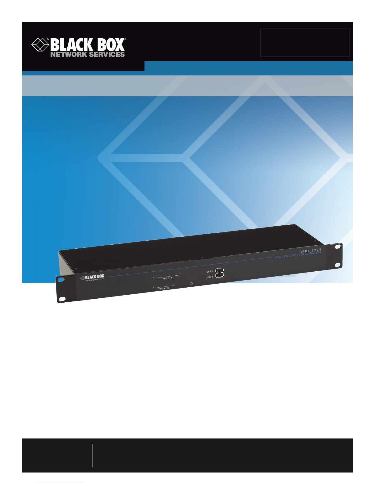
Hybrid PBX and VoIP Gateway with (4) or (12) FXOs
Installation Guide
Enables your office to communicate through both telephone and VoIP lines.
IPBX424
IPBX1224
Customer
Support
Information
Order toll-free in the U.S.: Call 877-877-BBOX (outside U.S. call 724-746-5500)
FREE technical support 24 hours a day, 7 days a week: Call 724-746-5500 or fax 724-746-0746
Mailing address: Black Box Corporation, 1000 Park Drive, Lawrence, PA 15055-1018
Web site: w ww.blackbox.com • E-mail: info@ blackbox.com
Page 2

724-746-5500 | blackbox.com
Trademarks Used in this Manual/Warnings and Cautions
Trademarks Used in this Manual
Black Box and the Double Diamond logo are registered trademarks of BB Technologies, Inc.
Aastra is a registered trademark of Aastra Technologies Limited Corporation Canada.
CIsco is a registered trademark of Cisco Technology, Inc.
GNOME is a registered trademark of GNOME Foundation.
SIPGate is a registered trademark of Indigo Networks GmbH.
Firefox is a registered trademark of Moziilla Foundation.
SanDisk Ultra and CompactFlash are registered trademarks of SanDisk Corporation.
SNOM is a registered trademark of Snom Technology AG.
babyTEL is a registered trademark of Voice & Data Systems, Inc.
Yealink is a registered trademark of Xiamen YeaLink Network Technology Co., Ltd.
Any other trademarks mentioned in this manual are acknowledged to be the property of the trademark owners.
Warnings and Cautions
It is important that you heed all warnings and cautions in this manual. They are identified as follows:
WARNING: Failure to follow a warning may cause injury, death, and/or hardware damage.
CAUTION: Failure to follow a caution may cause loss of data and/or configuration information, or cause equipment inoperability
and/or security concerns.
We‘re here to help! If you have any questions about your application
or our products, contact Black Box Tech Support at 724-746-5500
or go to blackbox.com and click on “Talk to Black Box.”
You’ll be live with one of our technical experts in less than 30 seconds.
Page 2
724-746-5500 | blackbox.com
Page 3

FCC and IC RFI Statements
Federal Communications Commission and Industry Canada Radio Frequency Interference
Statements
This equipment generates, uses, and can radiate radio-frequency energy, and if not installed and used properly, that is, in strict
accordance with the manufacturer’s instructions, may cause inter ference to radio communication. It has been tested and found to
comply with the limits for a Class A computing device in accordance with the specifications in Subpart B of Part 15 of FCC rules,
which are designed to provide reasonable protection against such interference when the equipment is operated in a commercial
environment. Operation of this equipment in a residential area is likely to cause interference, in which case the user at his own
expense will be required to take whatever measures may be necessary to correct the interference.
Changes or modifications not expressly approved by the party responsible for compliance could void the user’s authority to
operate the equipment.
This digital apparatus does not exceed the Class A limits for radio noise emis sion from digital apparatus set out in the Radio
Interference Regulation of Industry Canada.
Le présent appareil numérique n’émet pas de bruits radioélectriques dépassant les limites applicables aux appareils numériques de
la classe A prescrites dans le Règlement sur le brouillage radioélectrique publié par Industrie Canada.
724-746-5500 | blackbox.com
Page 3
Page 4

724-746-5500 | blackbox.com
NOM Statement
Instrucciones de Seguridad
(Normas Oficiales Mexicanas Electrical Safety Statement)
1. Todas las instrucciones de seguridad y operación deberán ser leídas antes de que el aparato eléctrico sea operado.
2. Las instrucciones de seguridad y operación deberán ser guardadas para referencia futura.
3. Todas las advertencias en el aparato eléctrico y en sus instrucciones de operación deben ser respetadas.
4. Todas las instrucciones de operación y uso deben ser seguidas.
5. El aparato eléctrico no deberá ser usado cerca del agua—por ejemplo, cerca de la tina de baño, lavabo, sótano mojado o cerca
de una alberca, etc.
6. El aparato eléctrico debe ser usado únicamente con carritos o pedestales que sean recomendados por el fabricante.
7. El aparato eléctrico debe ser montado a la pared o al techo sólo como sea recomendado por el fabricante.
8. Servicio—El usuario no debe intentar dar servicio al equipo eléctrico más allá a lo descrito en las instrucciones de operación.
Todo otro servicio deberá ser referido a personal de servicio calificado.
9. El aparato eléctrico debe ser situado de tal manera que su posición no interfiera su uso. La colocación del aparato eléctrico
sobre una cama, sofá, alfombra o superficie similar puede bloquea la ventilación, no se debe colocar en libreros o gabinetes
que impidan el flujo de aire por los orificios de ventilación.
10. El equipo eléctrico deber ser situado fuera del alcance de fuentes de calor como radiadores, registros de calor, estufas u otros
aparatos (incluyendo amplificadores) que producen calor.
11. El aparato eléctrico deberá ser connectado a una fuente de poder sólo del tipo descrito en el instructivo de operación, o como
se indique en el aparato.
12. Precaución debe ser tomada de tal manera que la tierra fisica y la polarización del equipo no sea eliminada.
13. Los cables de la fuente de poder deben ser guiados de tal manera que no sean pisados ni pellizcados por objetos colocados
sobre o contra ellos, poniendo particular atención a los contactos y receptáculos donde salen del aparato.
14. El equipo eléctrico debe ser limpiado únicamente de acuerdo a las recomendaciones del fabricante.
15. En caso de existir, una antena externa deberá ser localizada lejos de las lineas de energia.
16. El cable de corriente deberá ser desconectado del cuando el equipo no sea usado por un largo periodo de tiempo.
17. Cuidado debe ser tomado de tal manera que objectos liquidos no sean derramados sobre la cubierta u orificios de ventilación.
18. Servicio por personal calificado deberá ser provisto cuando:
A: El cable de poder o el contacto ha sido dañado; u
B: Objectos han caído o líquido ha sido derramado dentro del aparato; o
C: El aparato ha sido expuesto a la lluvia; o
D: El aparato parece no operar normalmente o muestra un cambio en su desempeño; o
E: El aparato ha sido tirado o su cubierta ha sido dañada.
Page 4
724-746-5500 | blackbox.com
Page 5

Table of Contents
Table of Contents
1. Specifications ................................................................................................................................................................... 7
2. Overview ................................................................................................................................................................... 8
2.1 Introduction ...........................................................................................................................................................8
2.2 What’s Included ..................................................................................................................................................... 8
2.3 Related Documentation .........................................................................................................................................8
2.4 Hardware Description ............................................................................................................................................9
2. 4.1 IPBX42 4 ...................................................................................................................................................... 9
2.4.2 IPBX1224 .................................................................................................................................................. 10
2.4.3 Hardware Features ................................................................................................................................... 11
3. Installation ................................................................................................................................................................. 14
3.1 Installation Examples ............................................................................................................................................ 14
3.2 Installation Steps .................................................................................................................................................. 16
3.2.1 Step 1: Prepare for Installation ................................................................................................................. 16
Step 1A: Inspect the Hybrid PBX and VoIP Gateway Hardware ................................................................ 16
Step 1B: Verify Package Contents ............................................................................................................ 16
Step 1C: Obtain Auxiliary Memory ........................................................................................................... 16
Step 1D: Configure Your Computer ......................................................................................................... 17
Step 1E: Obtain Networking Cables ......................................................................................................... 17
Step 1F: Obtain PSTN Network Connections ............................................................................................ 17
Step 1G: Install a Broadband Connection................................................................................................. 17
Step 1H: Sign Up for VoIP Service ............................................................................................................ 17
Step 1I: Collect Phone Information ........................................................................................................... 17
Step 1J: Read All Safety Disclaimers and Installation Warnings ................................................................ 18
3.2.2 Step 2: Install the Hybrid PBX and VoIP Gateway ..................................................................................... 18
Step 2A: Install Auxiliary Memory ............................................................................................................ 18
Step 2B: Connect Power .......................................................................................................................... 18
Step 2C: Connect All Cables .................................................................................................................... 18
3.2.3 Step 3: Run the Setup Wizard .................................................................................................................. 19
Step 3A: Review the Installation Checklist ................................................................................................ 21
Step 3B: Configure Administrator Account Credentials ............................................................................ 22
Step 3C: Set the System Date and Time ................................................................................................... 23
Step 3D: Configure Network Settings ...................................................................................................... 24
Step 3E: Configure Users .......................................................................................................................... 26
Step 3F: Configure Phones ....................................................................................................................... 29
Step 3G: Configure VoIP Lines ................................................................................................................. 31
Step 3H: Configure Ring Groups .............................................................................................................. 33
Step 3I: Configure Incoming Call Rules ....................................................................................................35
Step 3J: Configure Outgoing Call Rules .................................................................................................... 37
Step 3K: Configure Connections to a Remote Branch Office ...................................................................39
Step 3L: Configure Voicemail Settings ...................................................................................................... 41
Step 3M: Finish the Wizard and Apply Your Settings ............................................................................... 42
3.2.4 Step 4: Test Your Installation .................................................................................................................... 43
Step 4A: Connect to the Command Center ............................................................................................. 43
Step 4B: Verify Your Configuration ..........................................................................................................44
Step 4C: Connect a VoIP Phone and Make a Call .................................................................................... 47
Step 4D: Receive a Call ............................................................................................................................ 48
Step 4E: Record Voicemail ........................................................................................................................ 49
724-746-5500 | blackbox.com
Page 5
Page 6

724-746-5500 | blackbox.com
Table of Contents
Step 4F: Voicemail to Email ...................................................................................................................... 49
3.2.5 Step 5: What’s Next ............................................................................................................................................. 49
Step 5A: Create a Custom VoIP Template ............................................................................................................ 49
Step 5B: Configure Port Forwarding .................................................................................................................... 50
Step 5C: Customize the Sample IVR..................................................................................................................... 50
Step 5D: Record Voicemail Messages and Set Passwords .................................................................................... 50
Page 6
724-746-5500 | blackbox.com
Page 7

Chapter 1: Specifications
1. Specifications
Standards and Approvals — FCC Part 68, CE Mark, EMC: FCC Part 15
Interface — IPBX424: Telephone: (4) FXO, (1) FXS RJ-11; Network: (4) 10/100 Mbps RJ-45, Audio Input: Male stereo jack 1/8,
Audio Output: Male Stereo Jack 1/8, USB: USB 2.0 (1.1 Mbps);
IPBX1224: Telephone: (12) FXO, (4) FXS RJ-11; Network: (4) 10/100 Mbps RJ-45, Audio Input: Male stereo jack 1/8,
Audio Output: Male Stereo Jack 1/8, USB: USB 2.0 (1.1 Mbps)
Connectors — IPBX424: (4) FX0 ports for connection to the telephone network, (2) FXS ports for connecting a phone or fax
machine, (4) 10/100 Mbps auto MDI-X Ethernet ports; (2) USB ports, (1) audio input (mono) jack,
(1) audiio output (mono) jack;
IPBX1224: (12) FX0 ports for connection to the telephone network, (2) FXS ports for connecting a phone or fax machine,
(4) 10/100 Mbps Auto MDI-X Ethernet ports; (2) USB ports, (1) audio input (mono) jack, (1) audiio output (mono) jack
Indicators — (4) LEDs: Power, Fault, Network, Link Speed
Temperature Tolerance — Operating: 32 to 104° F (0 to +40° C);
Storage: -4 to +185° F (-20 to +85° C)
Humidity Tolerance — 10 to 80%
Power — Input: 100-240 VAC, 50-60 Hz, 0.5 A;
Ouptut: 12 VDC, 1.67 A, 20 W
Size — 2"H x 8.2"W x 5.4"D (5 x 20.5 x 13 cm)
724-746-5500 | blackbox.com
Page 7
Page 8

724-746-5500 | blackbox.com
Chapter 2: Overview
2. Overview
2.1 Introduction
This guide explains how to install a Hybrid PBX and VoIP Gateway with (4) FXO or (12) FXO (IPBX424 or IPBX1224) for basic
operation. Once you complete the installation process, refer to the Administrator’s Guide for instructions on how to perform more
advanced configuration tasks.
2.2 What’s Included
Your package should contain the following items. If anything is missing or damaged, contact Black Box Technical Support
at 724-746-5500 or [email protected].
IPBX424
• Hybrid PBX and VoIP Gateway with (4) FXO
• International power supply with three plug types
• 3-ft. (0.9-m) Category 5e RJ-45 cable
• (2) RJ-12 line splitters
• (2) RJ-12 telephone cable
• (2) rackmounting brackets
IPBX1224
• Hybrid PBX and VoIP Gateway with (12) FXO
• International power supply with three plug types
• 3-ft. (0.9-m) Category 5e RJ-45 cable
• (6) RJ-12 line splitters
• (6) RJ-12 telephone cable
• (2) rackmounting brackets
2.3 Related Documentation
The following documents are available at ftp://ftp.blackbox.com/anonymous/manuals/I/
Document File Location
Hybrid PBX and VoIP Gateway Administrator’s Guide ftp://ftp.blackbox.com/anonymous/manuals/I /ipbx424_admin_rev1.pdf
Hybrid PBX and VoIP Gateway Installation Guide (the manual you are reading now) ftp://ftp.blackbox.com /anonymous/manuals/I /ipbx424_install_rev1.pdf
Page 8
724-746-5500 | blackbox.com
Page 9
Chapter 2: Overview
2.4 Hardware Description
2.4.1 IPBX424
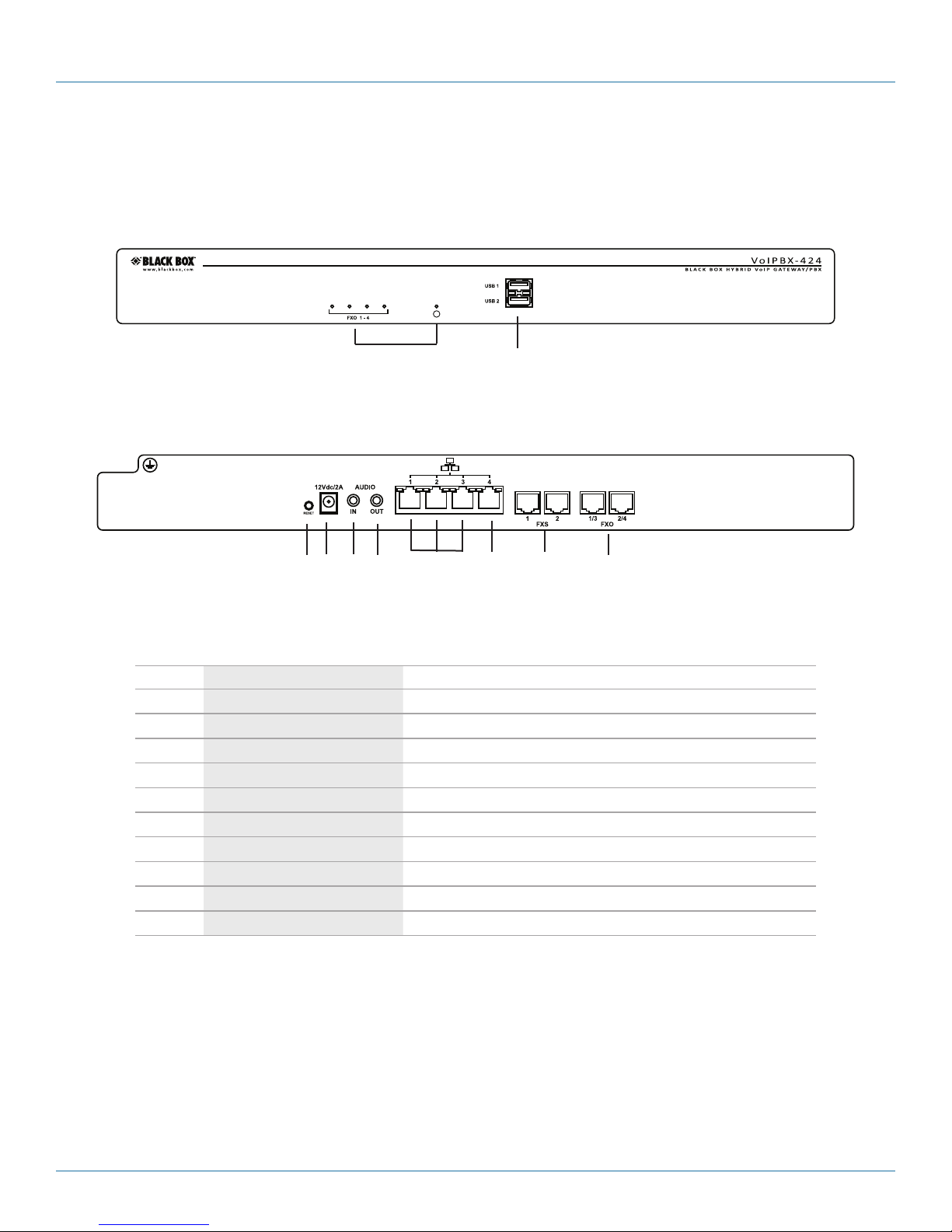
The front and back panels of the Hybrid PBX and VoIP Gateway with (4) FXO (IPBX424) are shown in Figures 2-1 and 2-2. Table
2-1 describes the components.
1 2
Figure 2-1. IPBX424 front panel.
3 4 5 6 7 8 9 10
Figure 2-2. IPBX424 back panel.
Table 2-1. IPBX424 components.
Number Component Description
1 (5) Status LEDs (4) FXO, (1) Circle (See Table 2-3.)
2 (2) USB ports USB Ports 1 and 2
3 Reset button Press with a paper clip or other object to reset the Hybrid PBX and VoIP Gateway.
4 Barrel connector for Power Links to power cord.
5 (1) RCA connector Used for audio in.
6 (1) RCA connector Used for audio out.
7 (3) R J-45 ports Connect s to LAN 1, 2, or 3.
8 (1) RJ-45 port Links to WAN.
9 (2) RJ-11 ports FXS Ports 1 and 2.
10 (2) RJ-11 ports FXO Por ts 1/3, 2/4.
724-746-5500 | blackbox.com
Page 9
Page 10
724-746-5500 | blackbox.com
Chapter 2: Overview
2.4.2 IPBX1224
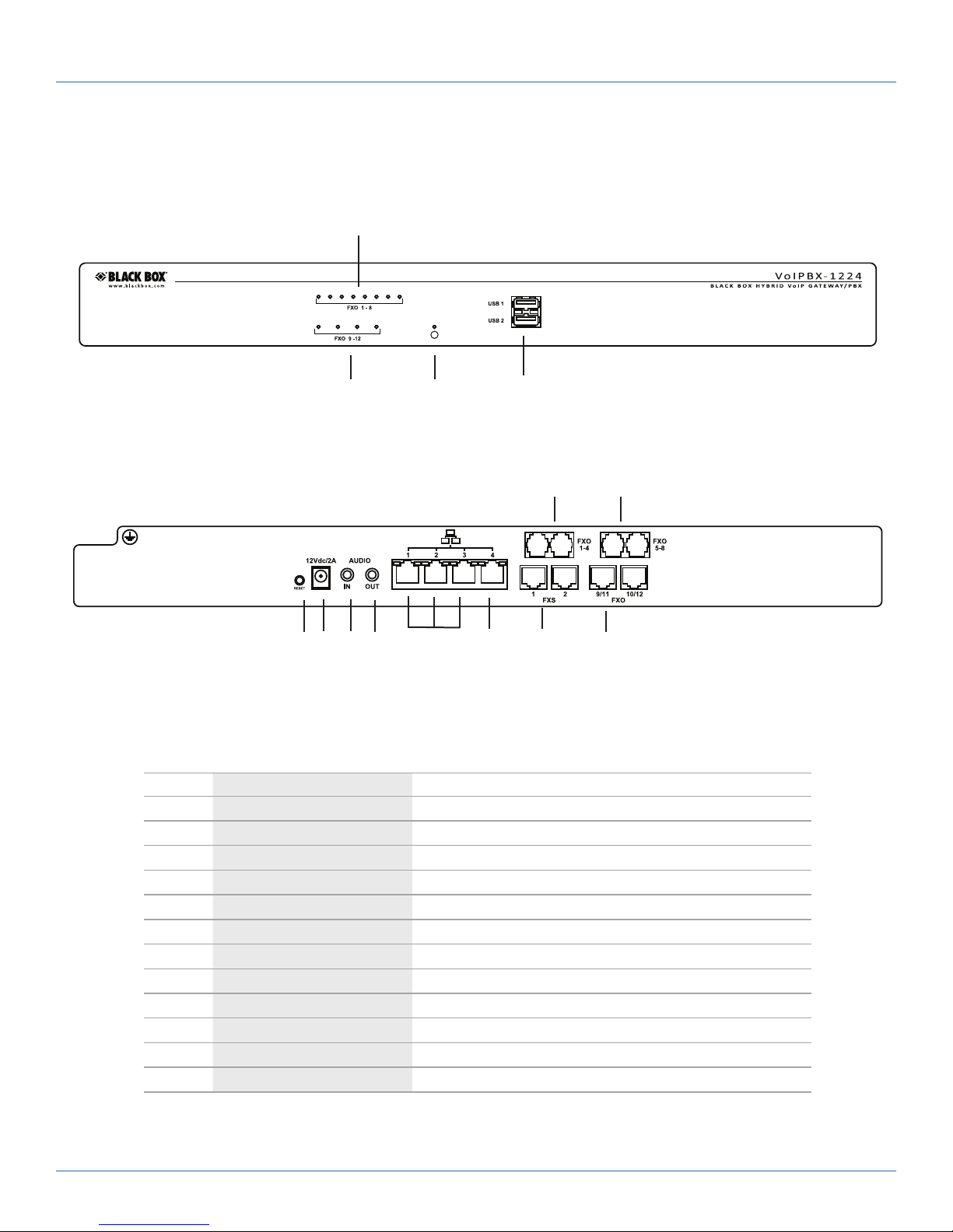
The front and back panels of the Hybrid PBX and VoIP Gateway with (12) FXO (IPBX1224) are shown in Figures 2-3 and 2-4. Table
2-2 describes the components.
1
1 1 2
Figure 2-3. IPBX1224 front panel.
11 12
3 4 5 6 7 8 9 10
Figure 2-4. IPBX1224 back panel.
Table 2-2. IPBX1224 components.
Number Component Description
1 (5) Status LEDs (4) FXO, (1) Circle (See Table 2-3.)
2 (2) USB ports USB Ports 1 and 2
3 Reset button Press with a paper clip or other object to reset the Hybrid PBX and VoIP Gateway.
4 Barrel connector for Power Links to power cord.
5 (1) RCA connector Used for audio in.
6 (1) RCA connector Used for audio out.
7 (3) R J-45 ports Connect s to LAN 1, 2, and 3.
8 (1) RJ-45 port Links to WAN.
9 (2) RJ-11 ports FXS Ports 1 and 2.
10 (2) R J -11 p or ts FXO Por ts 9/11, 10/12.
11 (2) RJ-11 ports FXO Por ts 1/2,. 3 /4
12 (2) RJ-11 ports FXO Ports 5/6, 7./8
Page 10
724-746-5500 | blackbox.com
Page 11
2.4.3 Hardware Features
This section describes the key hardware features of the Hybrid PBX and VoIP Gateway.
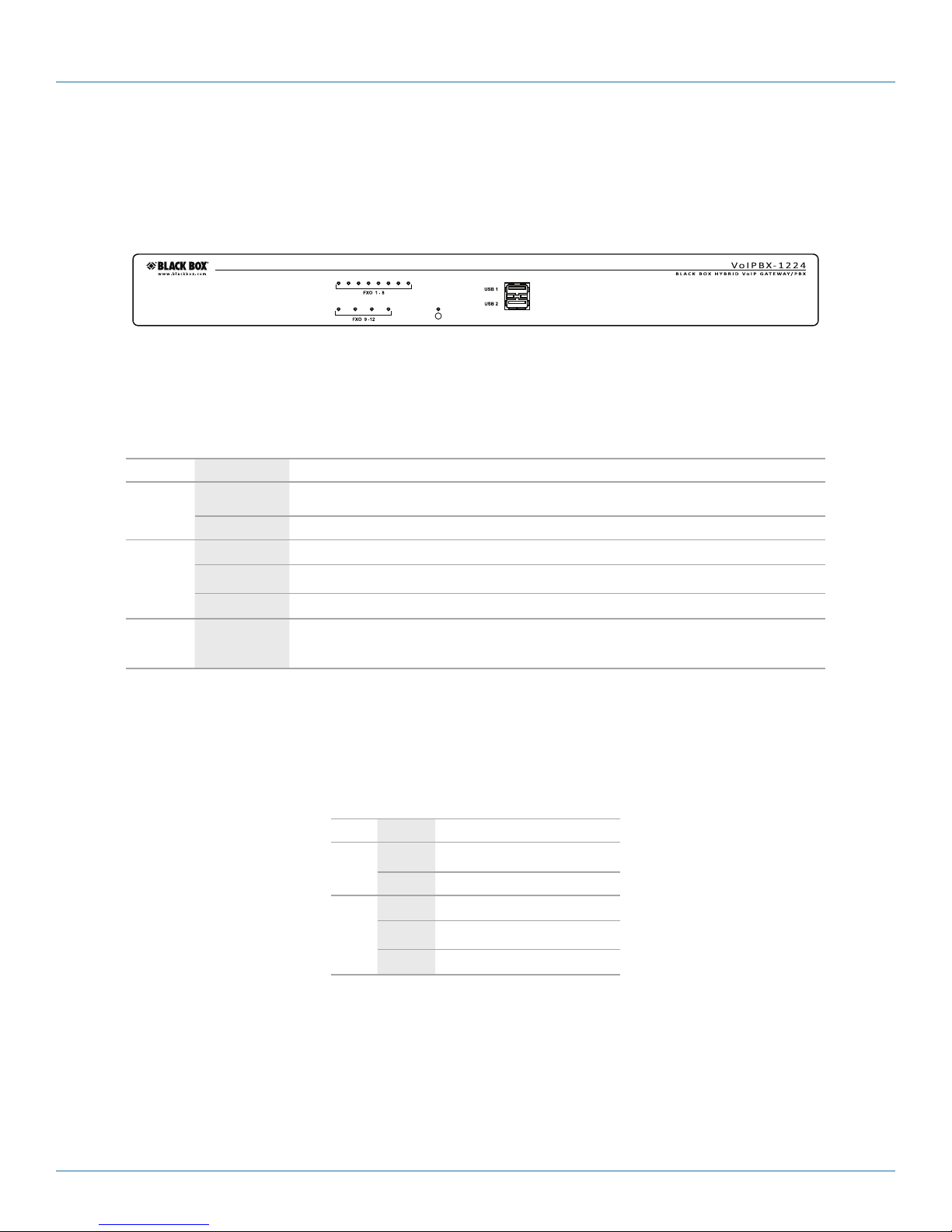
Front-panel status lights
Figure 2-5. Front-panel status lights.
Table 2-3. Front-panel status LEDs.
LED Status Description
Chapter 2: Overview
FXO
Circle
All lights On
Off The corresponding FXO port is not connected, or is connected to an analog phone line that is not operational.
On The corresponding FXO port is connected, or is connected to an analog operational phone line.
Off The Hybrid PBX and VoIP Gateway is off.
Blinking The Hybrid PBX and VoIP Gateway is starting up.
On The Hybrid PBX and VoIP Gateway is fully operational.
The Hybrid PBX and VoIP Gateway is not operational because of a fault. Possible causes include: incompatible
USB auxiliary memory device is installed, corrupt firmware, or hardware failure.
Ethernet port status lights
Each Ethernet port has two status lights.
Table 2-4. Ethernet port status lights.
LED Status Description
Off Port is operating at 10 Mbps.
Left
On Port is operating at 100 Mbps.
Off The port is not connected.
Blinking The port is sending/receiving data.
Right
USB ports
Both PBX models have two USB ports.
• One port can be used to connect auxiliary memory in the form of a USB drive. This provides additional storage for voicemail, call
recordings, and log files. Only one auxiliary memory device is supported at a time. For more information, see Section 3.2.1, Step
1C.
On The port is connected.
724-746-5500 | blackbox.com
Page 11
Page 12

724-746-5500 | blackbox.com
Chapter 2: Overview
• One port can be used to connect a 3G wireless Internet stick for failover support when VoIP and/or PSTN phone lines are not
available.
Reset button
Use the end of a paper clip to press the reset button.
• To restart the Hybrid PBX and VoIP Gateway, press and release the reset button. This is equivalent to disconnecting and then
reconnecting the power supply.
• To reset the Hybrid PBX and VoIP Gateway to factory default settings, press and hold the reset button until the first two FXO
lights on the left of the unit turn on.
Resetting to factory defaults erases all configuration settings. Auxiliary memory is not erased. When the Hybrid PBX and VoIP
Gateway restarts, the LAN ports will be set to the IP address 192.168.1.2. Any address configured on the WAN port is cleared.
Power connector
Connect the supplied power supply to this connector. The Hybrid PBX and VoIP Gateway does not have a power switch. It powers
up automatically when you connect the power supply.
CAUTION: Connecting any other power supply to this connector voids your warranty and may damage the Hybrid PBX and VoIP
Gateway.
Audio ports
The IPBX424 and IPBX1224 each have two mono mini-jack audio ports.
• Audio In: For connection of a music source for music-on-hold.
• Audio Out: For connection to a PA system for paging.
Ethernet ports
Both Hybrid PBX and VoIP Gateway models have four 10-/100-Mbps Ethernet ports with RJ-45 connectors. The ports are split
into the following two categories: LAN and WAN.
• LAN ports: Ports 1, 2, and 3 are LAN ports. These ports are generally used to connect the PBX to a local area network (LAN).
They can also be used to connect directly to a computer or SIP phone.
By default, the LAN IP address is set to 192.168.1.2.
For troubleshooting or system monitoring tasks, Port 3 can be switched into monitor mode, allowing it to capture all traffic on
Ports 1, 2, and 4.
• WAN port: Port 4 is called the WAN port. For certain installation scenarios, it can be used to connect the Hybrid PBX and VoIP
Gateway to the Internet or a private network that provides VoIP service.
NOTE: The LAN and WAN ports must have IP addresses on different networks.
NOTE: The Hybrid PBX and VoIP Gateway is not a router. It only forwards VoIP and voice traffic between its LAN and WAN ports.
This means that you cannot connect computers, SIP phones, or other IP-based devices to the Internet through the Hybrid
PBX and VoIP Gateway.
FXS ports
The FXS ports are used to connect the Hybrid PBX and VoIP Gateway to analog phone equipment, such as a telephone or fax
machine.
Failover support
The IPBX424 and IPBX1224 provide failover support on one FXS port. Thirty seconds after a power failure occurs, an FXS port is
automatically connected to an FXO line to enable calling from an analog phone.
Page 12
724-746-5500 | blackbox.com
Page 13

Chapter 2: Overview
Table 2-5. Failover support.
Model Failover support
IPBX424 FX2 is connected to FXO1.
IP BX1224 FXS2 us connected to F XO9.
FXO ports
The FXO ports are used to connect the Hybrid PBX and VoIP Gateway to analog phone lines. Support varies by model as follows:
.
Table 2-6. Number of FXO ports supported.
Model FXO ports
IPBX424 4
IP BX1224 12
724-746-5500 | blackbox.com
Page 13
Page 14
724-746-5500 | blackbox.com
Chapter 3: Installation
3. Installation
3.1 Installation Examples
There are a wide variety of ways to integrate the Hybrid PBX and VoIP Gateway into your existing networking infrastructure. To
simplify the installation process, this guide recommends the following two scenarios:
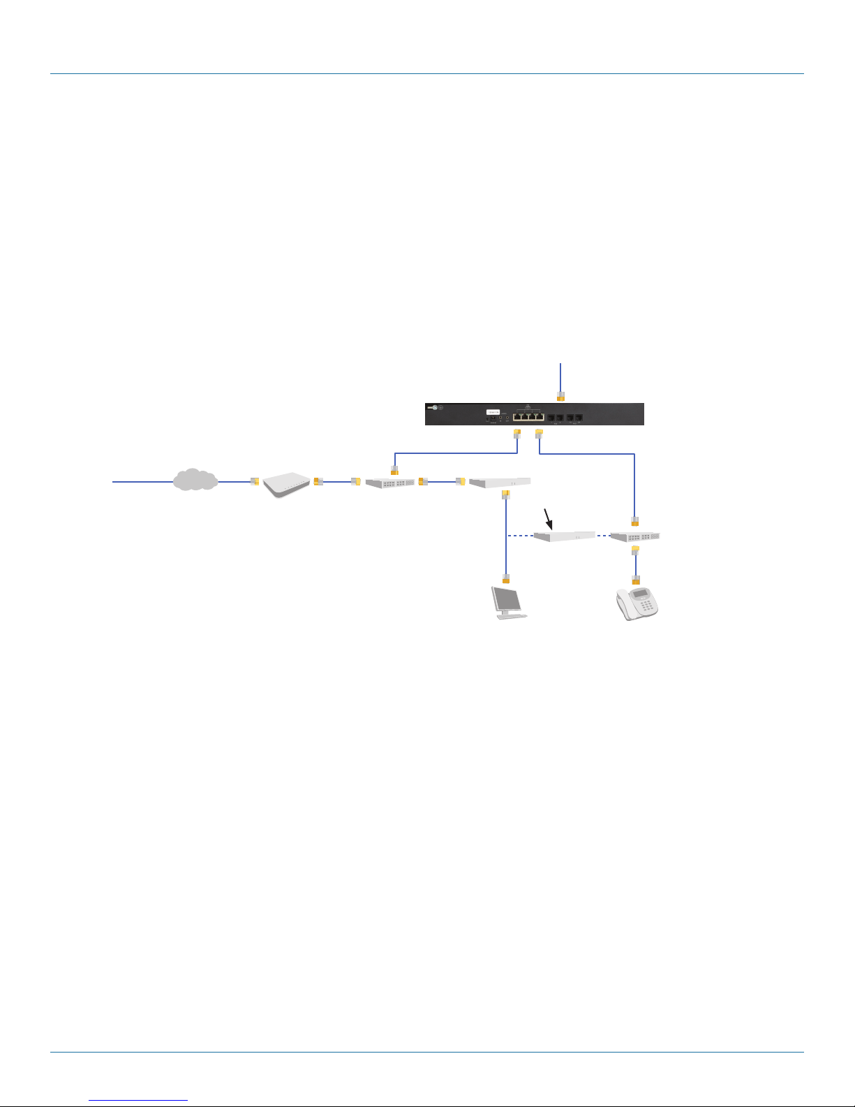
Example 1
This scenario illustrates one way to add the Hybrid PBX and VoIP Gateway to a network to take advantage of an existing broadband Internet connection for VoIP service.
Public Switched
Telephone
Network (PSTN)
LAN port 1
192.16 8.1. 2
Router
192.16 8.1.1
192.168.0.2
This router and the
connection
between the two
networks are only
needed if the SIP
phones require
Internet access.
Analog phone lines
connected to FXO ports
DHCP server for
192.16 8.1. 0/2 4
DHCP Gateway
and DHS server set
to 192.1 68 .1.1
Managed
switch with
PoE support
192.16 8.1. 0/2 4
SIP phones
VoIP
Provider
Internet
Broadband
modem
Gateway/ Router
DHCP server for
192.168.0.0/24
DHCP gateway and
DNS server set to
192.16 8. 0.1
Hybrid PBX and
VoIP Gateway
(IPBX424 )
WAN port with static
public IP address
192.168.0.0/24
Computers
In this scenario, the connection to the VoIP provider is made using the LAN Port 1 on the Hybrid PBX and VoIP Gateway. Traffic
from the SIP phones (green line) reaches the Hybrid PBX and VoIP Gateway on its LAN port and is then sent to the VoIP provider
through the gateway/router installed on the network. Port forwarding is configured on the Gateway/Router to send traffic from
the VoIP provider to the Hybrid PBX and VoIP Gateway. (See “Configure port forwarding”in Section 3.2.5, Step 5B.)
The Hybrid PBX and VoIP Gateway acts as the DHCP for the network, enabling it to automatically provision the SIP phones.
However, to support Internet access (yellow line), it assigns the Gateway/Router as the DNS server and default gateway for all network devices.
(If your existing DHCP server supports Option 66, you can continue to use it if you make configuration adjustments. For details,
see Configuring a third-party DHCP server in the Networking chapter in the Hybrid PBX and VoIP Gateway Administrator’s Guide.)
Page 14
Figure 3-1. Example 1.
724-746-5500 | blackbox.com
Page 15
Chapter 3: Installation
Example 2
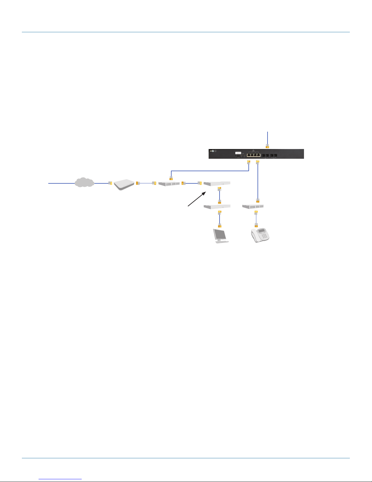
In this scenario, the Hybrid PBX and VoIP Gateway WAN port is directly connected to a switch provided by the Internet ISP. Traffic
from the SIP phones (green line) reaches the Hybrid PBX and VoIP Gateway on its LAN port and is then sent to the VoIP provider
via the WAN port. One advantage of this setup is that the WAN port gets a public IP address on the Internet. This makes it easy
to configure VoIP support and provide access for remote phone, as port forwarding does not have to be configured on the
Gateway/Router as in scenario 1.
Public Switched
Telephone
Network (PSTN)
Hybrid PBX and
VoIP Gateway
(IPBX424 )
DHCP server for
192.16 8.1. 0/2 4
DHCP Gateway
and DHS server set
to 192.1 68 .1.1
VoIP
Provider
Internet
Broadband
modem
ISP’s Router/
Switch
Gateway/ Router
DHCP server is off
WAN port with static
public IP address
192.16 8.1.1
LAN port 1
192.16 8.1. 2
Managed
switch with
PoE support
Computers
All devices are on
the same subnet
192.16 8.1. 0/2 4
SIP phones
Figure 3-2. Example 2.
As in Example 1, the Hybrid PBX and VoIP Gateway acts as the DHCP for the network, allowing it to automatically provision the
SIP phones. However, to support Internet access (yellow line), it assigns the gateway/router as the DNS server and default gateway
for all network devices.
(If your existing DHCP server supports Option 66, you can continue to use it if you make configuration adjustments. For details,
see Configuring a third-party DHCP server in the Networking chapter in the Hybrid PBX and VoIP Gateway Administrator’s Guide.)
Other installation examples
For other installation scenarios, see the Hybrid PBX and VoIP Gateway Administrator’s Guide.
724-746-5500 | blackbox.com
Page 15
Page 16

724-746-5500 | blackbox.com
Chapter 3: Installation
3.2 Installation Steps
3.2.1 Step 1: Prepare for Installation
Prepare the following to ensure a fast and efficient installation of the Hybrid PBX and VoIP Gateway.
STEP 1A: Inspect the Hybrid PBX and VoIP Gateway hardware.
Inspect the Hybrid PBX and VoIP Gateway hardware for any signs of physical damage during shipping. Report any damage to
Black Box Technical Suppport at 724-746-5500 or [email protected].. Keep all packaging material in case the Hybrid PBX and
VoIP Gateway has to be returned for servicing.
STEP 1B: Verify package contents.
Verify that the package contains the following items. If an item is missing, contact Black Box Technical Suppport at 724-746-5500
or [email protected].
Table 3-1. Package contents.
Item Quantity for IPBX424 Quantity for IPBX1224
Hybrid PBX and VoIP Gateway 1 1
Interanational power supply with three plug types 1 1
3-ft. (0.9-m) Category 5e RJ-45 Ethernet cable 1 1
RJ-12 line splitter 2 6
RJ-12 telephone cable 2 6
Rackmounting brackets 2 2
STEP 1C: Obtain auxiliary memory.
The Hybrid PBX and VoIP Gateway uses auxiliary memory to store:
• Voicemail for each user
• Voicemail and name directory greetings
• Call recordings
• Log files
If auxiliary memory is not installed, these items are stored in system memory. A limited amount of system memory is available
for this purpose. Once full, new items are discarded—this can cause system errors. We strongly recommend that you install
auxiliary memory.
One GB of auxiliary memory will store approximately 1000 minutes of voicemail and/or call recordings.
Memory types
Both models of the Hybrid PBX and VoIP Gateway support auxiliary memory (USB flash drive).
CAUTION: Never remove a USB flash drive when the Hybrid PBX and VoIP Gateway is on. This can result in a loss of data.
Formatting auxiliary memory
Auxiliary memory devices larger than 50 GB must be formatted on a computer before installation. The required file format is ext2,
which can be created using third-party software such as the Gnome® Partition Editor - GParted Live (available for download at:
http://gparted.sourceforge.net/index.php).
Page 16
724-746-5500 | blackbox.com
Page 17

Chapter 3: Installation
STEP 1D: Configure your computer.
To configure the Hybrid PBX and VoIP Gateway, you must log into its Web-based command center. This requires a computer with
an Ethernet port and a Web browser. We recommend using Mozilla Firefox® to ensure complete compatibility with the command
center. Other browsers may also work.
In this guide, the computer that connects to the command center is called the management computer. Initially, it should be
configured on subnet 192.168.1.0 with an IP address that is greater than 192.168.1.2.
STEP 1E: Obtain networking cables.
You will need at least three Category 5 Ethernet cables of sufficient length to connect the Hybrid PBX and VoIP Gateway to your
computer, and the switch or router on your network.
STEP 1F: Obtain PSTN network connections.
If you are going to connect traditional analog phone lines to the Hybrid PBX and VoIP Gateway, you will need your local phone
company to install one or more PSTN phone lines.
STEP 1G: Install a broadband connection.
If you are going to use VoIP to make and receive phone calls with the Hybrid PBX and VoIP Gateway, then you need to have a
broadband connection to the Internet. Internet connections should be made via either DSL or cable to ensure enough bandwidth
is available to handle phone traffic from the Hybrid PBX and VoIP Gateway.
If you are using the existing gateway/router on your network to connect to the Internet, record the IP address of the router on
the LAN.
STEP 1H: Sign up for VoIP service.
To successfully make VoIP calls you will need one or more VoIP lines configured on your broadband connection. Collect the
following information from your VoIP service provider:
• Name of your VoIP service provider.
• Protocol supported by the VoIP line. The Hybrid PBX and VoIP Gateway supports SIP or IAX2.
• Authentication method. The Hybrid PBX and VoIP Gateway supports either SIP username and password, or just an IP address.
STEP 1I: Collect phone information
Gather the following information for each VoIP phone that will connect to the Hybrid PBX and VoIP Gateway:
• Manufacturer
• Model number
• MAC Address of the phone. The MAC address is usually printed on a label on the phone. It is 12 hexadecimal numbers in the
format: nn:nn:nn:nn:nn:nn. For example:
724-746-5500 | blackbox.com
Page 17
Page 18

724-746-5500 | blackbox.com
Chapter 3: Installation
Figure 3-3. Sample MAC address printed on label.
STEP 1J: Read all safety disclaimers and installation warnings (see below).
Power
Only use the power supply provided with the Hybrid PBX and VoIP Gateway. The Hybrid PBX and VoIP Gateway is shipped with
an international plug system rated at 12V/2A. Failing to use the included power supply will void your warranty.
PSTN connections
The Hybrid PBX and VoIP Gateway has been designed to be connected to the public switched telephone network (PSTN) and
should not be connected to any other type of telecommunications service or services. Doing so will void your warranty and may
cause
damage to the Hybrid PBX and VoIP Gateway or any connected network equipment.
Environment
Install the Hybrid PBX and VoIP Gateway in a location that is clean, and free from vibration, electric shock, and temperature/
humidity extremes. The operating temperature should be kept below 104° F (40° C).
3.2.2 STEP 2: Install the Hybrid PBX and VoIP Gateway
The following steps describe how to install the Hybrid PBX and VoIP Gateway hardware and connect all cables for a typical installation.
STEP 2A: Install auxiliary memory.
Install auxiliary memory in a USB port. For requirements, see Section 3.2.1, STEP 1C.
STEP 2B: Connect power.
Connect the power supply to the Hybrid PBX and VoIP Gateway.
• When the Circle light stops blinking, the PBX is fully operational.
• If all the status lights turn on, it means a hardware fault has occurred. Disconnect power, then reconnect power. If the fault
condition persists, contact Black Box Technical Support at 724-746-5500 or [email protected].
STEP 2C: Connect all cables.
Connect the Ethernet ports.
Make the following connections using standard Category 5 Ethernet cables.
• Connect Ethernet Port 1 to the network that provides connectivity to your SIP phones.
• Connect Ethernet Port 2 to the computer you will use to initially configure the Hybrid PBX and VoIP Gateway.
Page 18
724-746-5500 | blackbox.com
Page 19

Chapter 3: Installation
• If installing Scenario 2, connect the Ethernet Port 4 to the ISP’s router/switch.
Connect the FXO ports
• Connect the analog phone lines supplied by your phone company to the FXO ports. You will need to use line splitters since
each port supports two lines.
• To support failover, make sure that you connect an analog line to:
• FXO1 on the IPBX424
• FXO9 on the IPBX1224
Connect the FXS ports
• On the IPBX424, connect an analog phone to FXS1. During a power failure, FXS1 is bridged to FXO1, allowing you to make
analog phone calls. Connect another analog device (such as a fax machine), to FXS2.
• On the IPBX1224, connect an analog phone to FXS2. During a power failure, FXS2 is bridged to FXO9, allowing you to make
analog phone calls. Connect another analog device (such as a fax machine), to FXS1.
Connect audio ports
• Connect the Audio In port to an external audio source (to provide music on hold).
• Connect the Audio Out port to a paging system.
3.2.3 STEP 3: Run the setup wizard
The Hybrid PBX and VoIP Gateway is configured using its Web-based command center that you access using the Web browser on
your computer. For requirements, see Section 3.2.1, STEP 1D: Configure your computer.
NOTE: The setup wizard only runs the first time you start the command center after a factory reset.
To start the setup wizard:
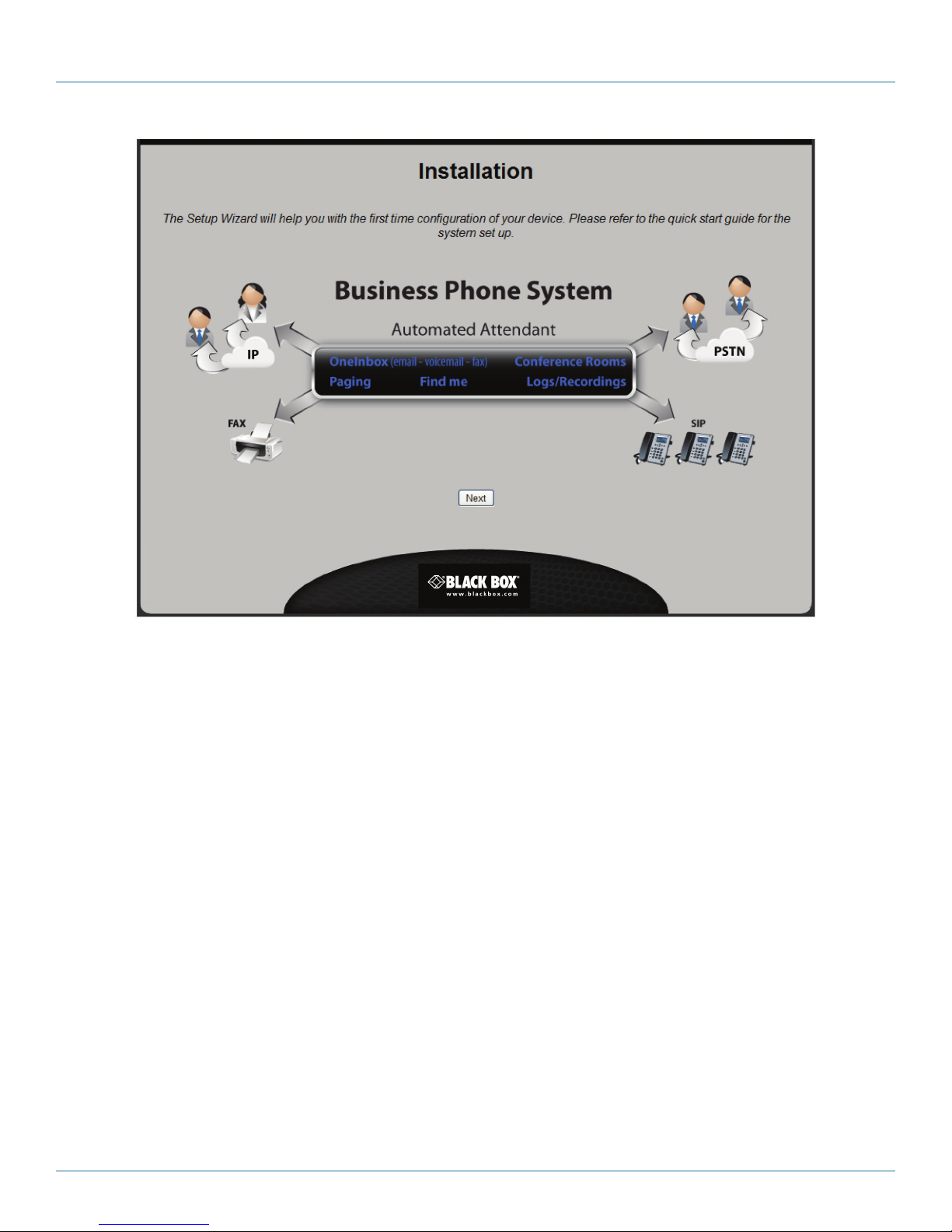
Specify http://192.168.1.2 in the address bar of your browser and press “Enter.” The Start page for the Setup Wizard opens.
724-746-5500 | blackbox.com
Page 19
Page 20
724-746-5500 | blackbox.com
Chapter 3: Installation
Click “Next” to continue.
Figure 3-4. Setup Wizard screen.
Page 20
724-746-5500 | blackbox.com
Page 21
Chapter 3: Installation
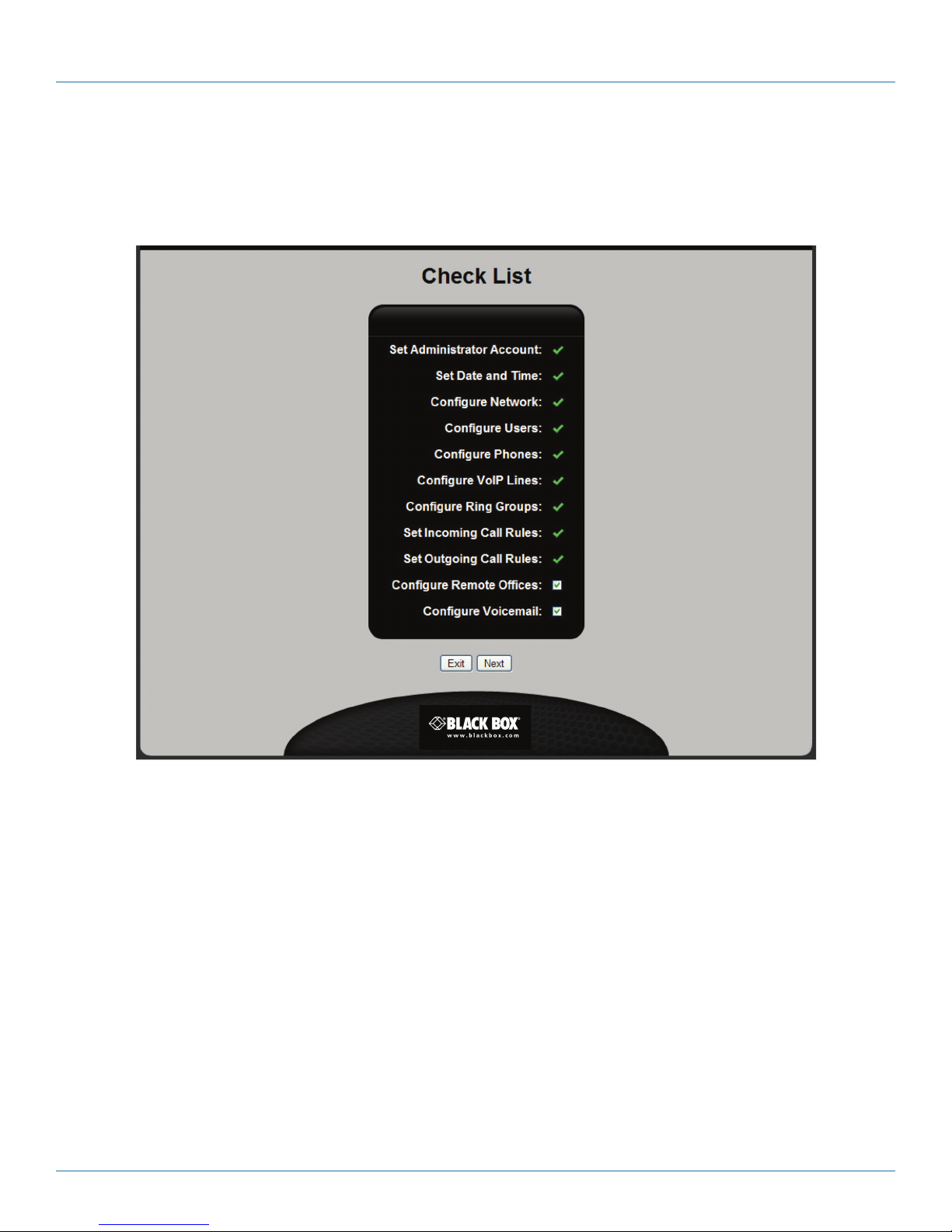
STEP 3A: Review the installation checklist.
This page shows all the configuration tasks that the wizard will help you to complete. There are two optional tasks at the end of
the list. Clear the checkmarks for these tasks if they do not apply to your installation. (You can customize these settings after
running the wizard if you need to.)
Click “Next” to continue.
Figure 3-5. Installation Checklist screen.
724-746-5500 | blackbox.com
Page 21
Page 22
724-746-5500 | blackbox.com
Chapter 3: Installation
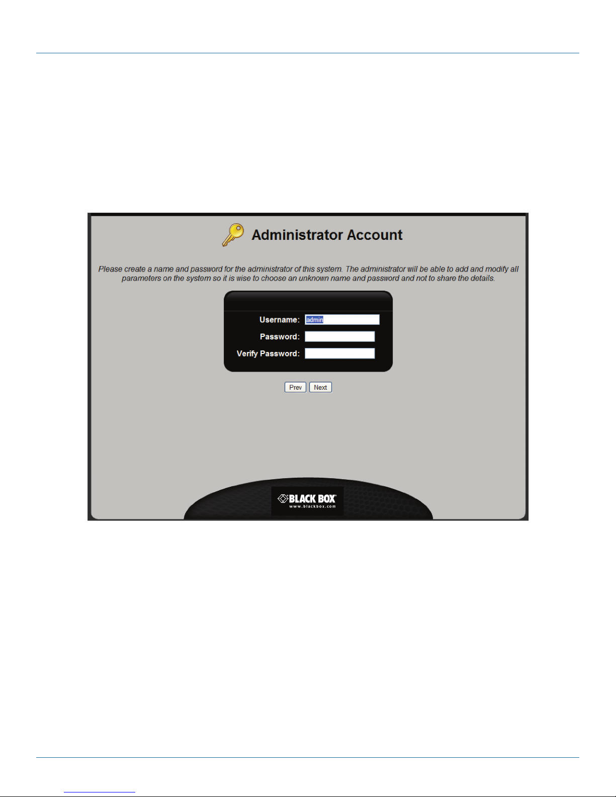
STEP 3B: Configure administrator account credentials.
The administrator is able to define and modify all configuration settings. To safeguard access to the administrator account, we
strongly recommend that you define a password as follows:
• At least 12 characters long.
• Contains a combination of uppercase/lowercase letters and numbers.
• Contains at least one symbol.
Click “Next” to continue.
Page 22
Figure 3-6. Administrator Account screen.
724-746-5500 | blackbox.com
Page 23
Chapter 3: Installation
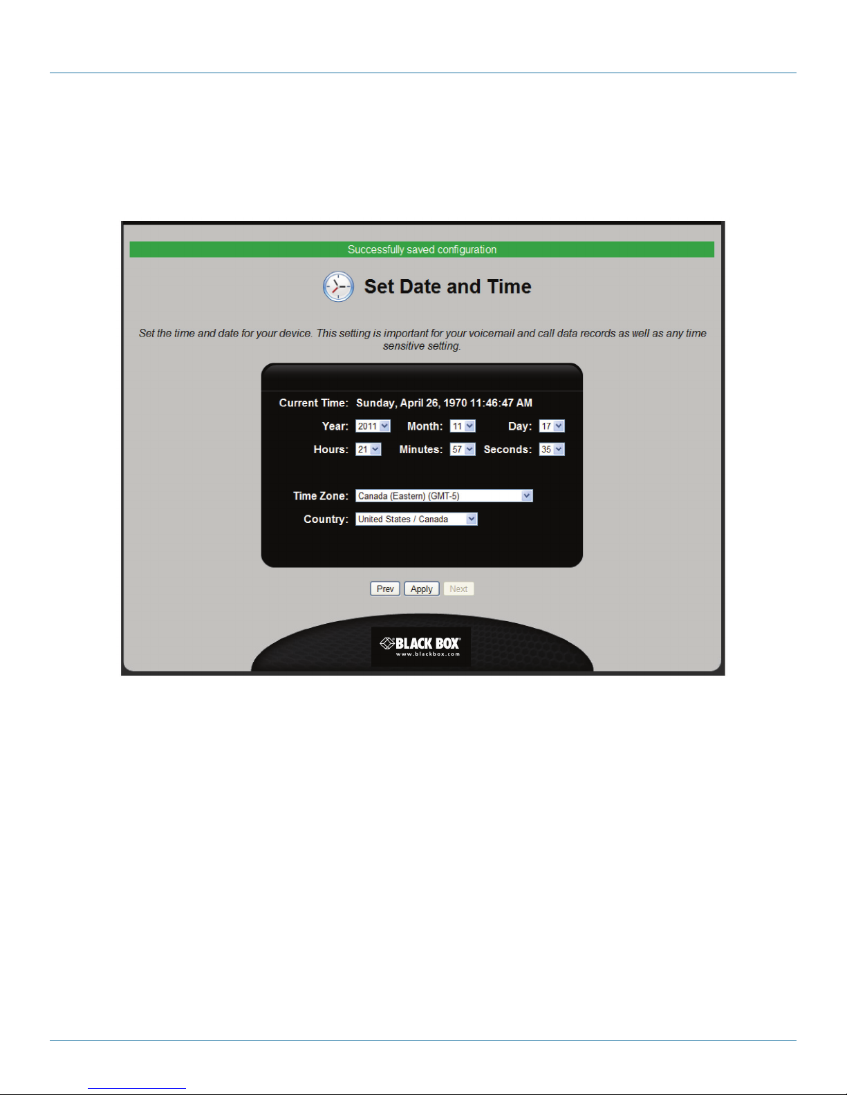
STEP 3C: Set the system date and time.
Correct date and time settings are important for proper operation of the Hybrid PBX and VoIP Gateway. For example, it ensures
that
voicemail and call data records are time-stamped correctly.
Define configuration settings as described below. When done, click “Apply,” and then click “Next” to continue.
• Current time: Shows the correct time on the Hybrid PBX and VoIP Gateway.
• Year, Month, Day, Hours, Minutes, Seconds: Use these fields to define the new system time. By default, these fields are set to
match the time and date on your computer.
• Time Zone: Select the time zone in which the Hybrid PBX and VoIP Gateway is located. When the Hybrid PBX and VoIP
Gateway is connected to the Internet, it automatically retrieves accurate time and date settings (from an ntp server) based on
the Time Zone you enter.
Figure 3-7. Set Date and Time screen.
724-746-5500 | blackbox.com
Page 23
Page 24
724-746-5500 | blackbox.com
Chapter 3: Installation
• Country: Select the country in which the Hybrid PBX and VoIP Gateway is located.
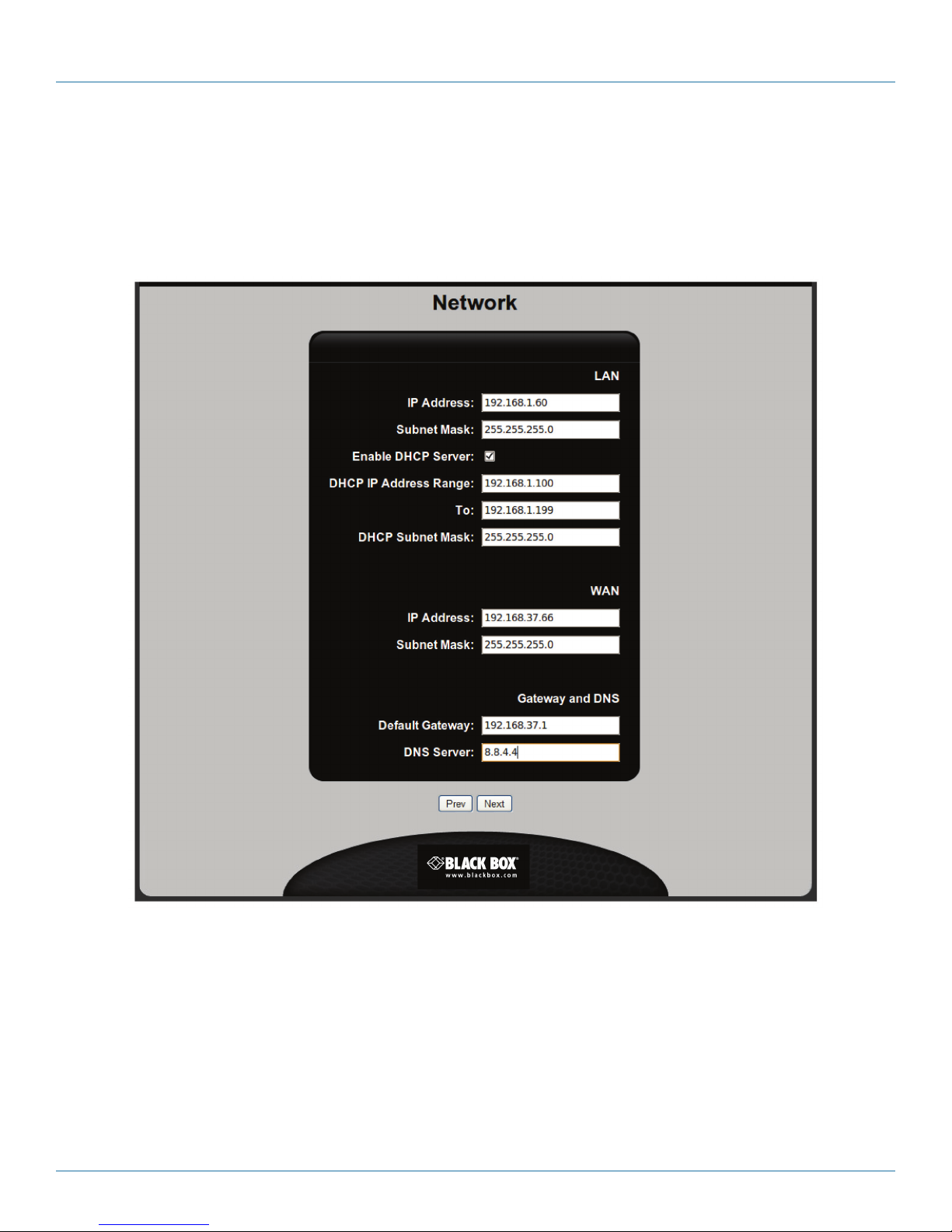
STEP 3D: Configure network settings.
Define the appropriate network settings to properly connect the Hybrid PBX and VoIP Gateway to your LAN and your VoIP provider.
Define configuration settings as described in the following section. When done, click “Next” to continue.
LAN
Use these fields to assign an IP address to Ports 1, 2, and 3. (These ports share the same IP address.)
• IP address: Specify an IP address in dotted-decimal notation (nnn.nnn.nnn.nnn). By default, 192.168.1.2 is assigned. If you
change this address you will lose contact with the command center when the wizard completes. You will have to log in again
with the new address you assign.
• Subnet Mask: Specify a subnet mask that is appropriate for the address you entered. By default, the mask is set to
255.255.255.0.
Page 24
Figure 3-8. Network Settings screen.
724-746-5500 | blackbox.com
Page 25

Chapter 3: Installation
• Enable DHCP Server: For most installations, it is recommended that the Hybrid PBX and VoIP Gateway acts as the DHCP server
for your network. This will make it easier to manage the IP address assigned to your VoIP phones, allow for automatic phone
provisioning, and ensure that the proper gateway and DNS servers are assigned. If you are connected to the Internet via cable or
DSL, the broadband router/modem is generally set up as the DHCP server. Therefore, before you connect the Hybrid PBX and
VoIP Gateway to your network, you should disable DHCP server support on this device.
• DHCP IP Address Range: Specify the starting IP address for the DHCP address pool. Default: 192.168.1.100
• To: Specify the ending IP address for the DHCP address pool. Default: 192.168.1.199
• DHCP Subnet Mask: Specify the subnet mask for all DHCP addresses. Default: 255.255.255.0
WAN
The WAN port is not used in all installation scenarios.
If your scenario makes use of the WAN port to connect the Hybrid PBX and VoIP Gateway to the Internet via a broadband router,
configure settings as follows:
• IP address: Specify an IP address in dotted-decimal notation (nnn.nnn.nnn.nnn). By default, no address is assigned. If you are
connected to the Internet via cable or DSL the router/modem, you must assign an address that is on the same subnet as the
router/modem.
• Subnet Mask: Specify the subnet mask that is appropriate for the address you entered. By default, the mask is set to
255.255.255.0.
Gateway and DNS
• Default Gateway: Specify the IP address of the default gateway on your network. This is the device that provides access to the
Internet.
• DNS Server: Specify the IP address of the primary DNS server. This will be the address of default gateway.
724-746-5500 | blackbox.com
Page 25
Page 26
724-746-5500 | blackbox.com
Chapter 3: Installation
STEP 3E: Configure users.
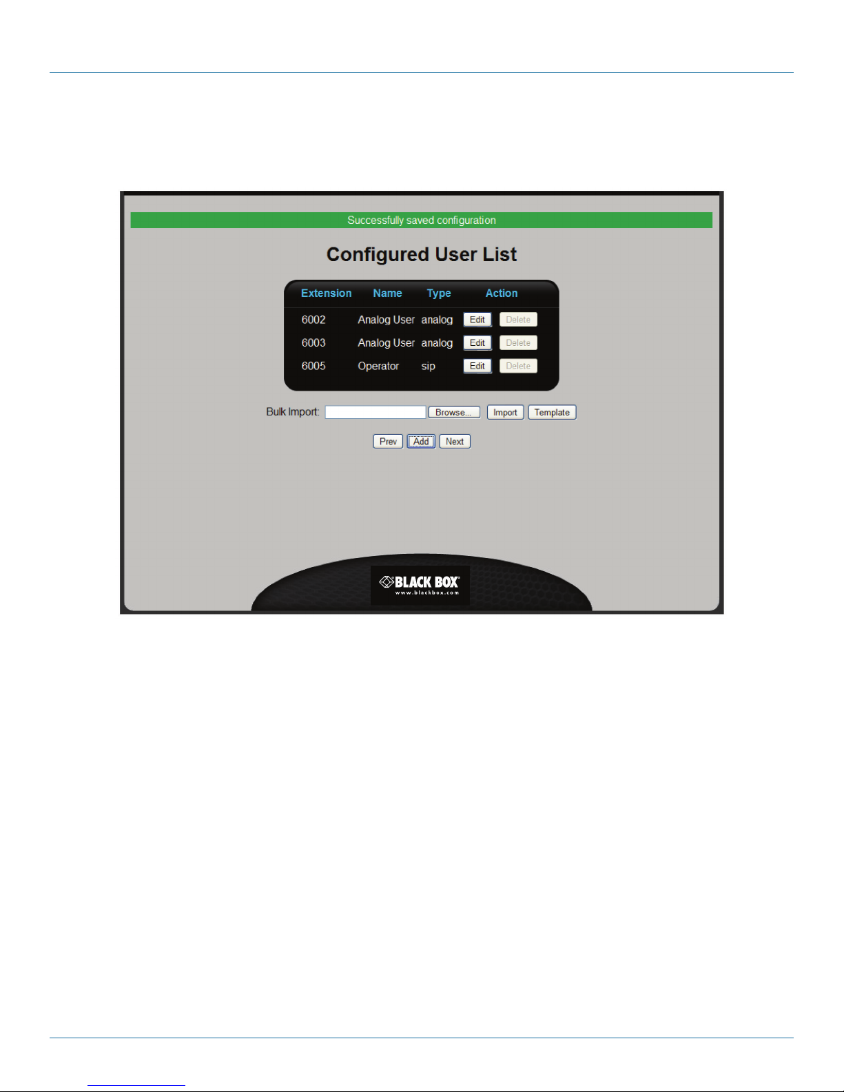
In this step, you configure all users that can make and receive calls through the Hybrid PBX and VoIP Gateway.
Figure 3-9. Configured User List screen.
• To add a new user, click “Add” and then see “Adding a user” on the next page.
• To import user definitions from a spreadsheet file, see “Importing user definitions from a spreadsheet” in the Administrator’s
Guide.
• When done, click “Next” to continue.
Configured User List
This table lists all defined users. The following information is presented for each user.
• Extension: Extension number assigned to the user. Extensions must be three to six digits long.
• Name: Name assigned to the user.
• Type: One of the following extension types:
- SIP: The extension is connected to a SIP phone.
- Voicemail Box: The extension is connected to a voicemail box.
Page 26
724-746-5500 | blackbox.com
Page 27
Chapter 3: Installation
• Action: Click the appropriate button to Edit or Delete a user. The Edit button displays the User page. For details, see “Adding a
user,” below.
Default users
The following users are defined by default. You can edit them, but you cannot delete them in the wizard.
• Analog User: This user is mapped to port FXS1 using extension 6002.
• Analog User: This user is mapped to port FXS2 using extension 6003.
• Operator: Sample SIP account using extension 6005.
Adding a user
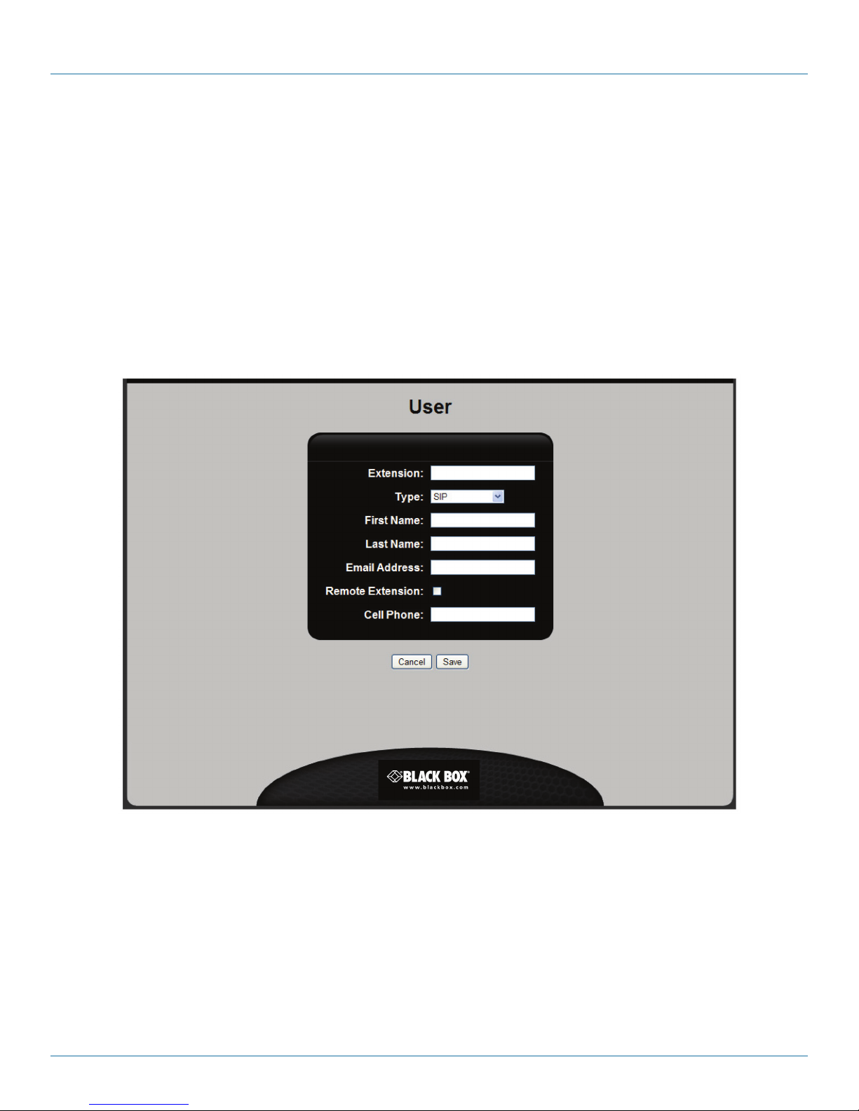
When you click “Add” on the Configured User List page, you open the User page. Use this page to define or edit the
configuration settings for a user.
Configure the following settings, and click “Save” when you are done.
• Extension: Specify the extension number assigned to the user. Extensions must be between three and six digits in length.
• Type: Extension type. Select one of the following:
- SIP: Select this option if the user will make and receive calls on a SIP phone.
- Voicemail Box: Select this option to set up a virtual voicemail box that is not associated with a physical user. For example:
-- A sales department could use a virtual voicemail box to store all incoming customer requests. All members of the sales
team would have access to this box to retrieve and process messages.
Figure 3-10. User screen.
724-746-5500 | blackbox.com
Page 27
Page 28

724-746-5500 | blackbox.com
Chapter 3: Installation
-- A ring group could use a virtual voicemail box to record messages from calls that were not answered.
-- A user without a SIP phone could use a virtual voicemail box to record incoming messages and have them automatically
forwarded to an e-mail address.
• First Name: User’s first name. Used by the Dial by Name directory feature.
• Last Name: User’s last name. Used by the Dial by Name directory feature.
• E-mail address: E-mail address where voicemail will be sent. If you enable the Voicemail to Email feature (when you configure
the Voicemail option later in the wizard), voicemail messages for this user are automatically sent to the address you specify (as
wav files).
• Remote Extension: If you enable this option, the account is created with the default PTS-External template. This template
prevents users from making long-distance calls. One application for this feature is to safeguard accounts for remote users (users
that connect to the Hybrid PBX and VoIP Gateway from a remote location directly with a SIP phone). By limiting remote users to
local calls, you greatly reduce the potential charges that could occur if the account password was compromised and a third-party attempted to make calls through the Hybrid PBX and VoIP Gateway.
• Cell Phone: User’s cell phone number. Allows other local users to reach the user’s cell phone automatically by dialing 7 and the
extension number. For example, if the extension is 2233, then any internal user can reach the cell phone by dialing 72233.
Importing user definitions from a spreadsheet
A quick way to build the user list is to import definitions from a spreadsheet as follows:
1. Click the “Template” button to download a sample spreadsheet file to your computer.
2. Add user information to the spreadsheet according to the directions in the file. Save the file when you are done. Do not change
the file extension from .csv. Only .csv files can be uploaded to the Hybrid PBX and VoIP Gateway.
3. In the wizard, click “Browse” and then select the spreadsheet file on your computer. Click “OK.”
4. Click “Import” to load the definitions. Each definition is checked during import. If there is a configuration error, the definition is
discarded.
Page 28
724-746-5500 | blackbox.com
Page 29
Chapter 3: Installation
STEP 3F: Configure phones.
All VoIP phones that will be used with the Hybrid PBX and VoIP Gateway can be added to the phone list and then provisioned
with the proper operational settings.
The Hybrid PBX and VoIP Gateway can automatically provision phones from Aastra®, SNOM®, and Yealink®. Once the wizard is
complete, and the Hybrid PBX and VoIP Gateway has restarted, all you need to do is plug these phones into your network, and
they will retrieve their configuration settings from the Hybrid PBX and VoIP Gateway and become fully operational.
NOTE: If the Hybrid PBX and VoIP Gateway is not configured as the DHCP server on your network, or phones from other manu-
facturers are being used, additional configuration steps may be required.
• To add new phones, click Add and see “Adding a phone” on the next page.
• To import phone definitions from a spreadsheet file, see “Importing phone definitions from a spreadsheet” n the
Administrator’s Guide.
• When done, click “Next” to continue.
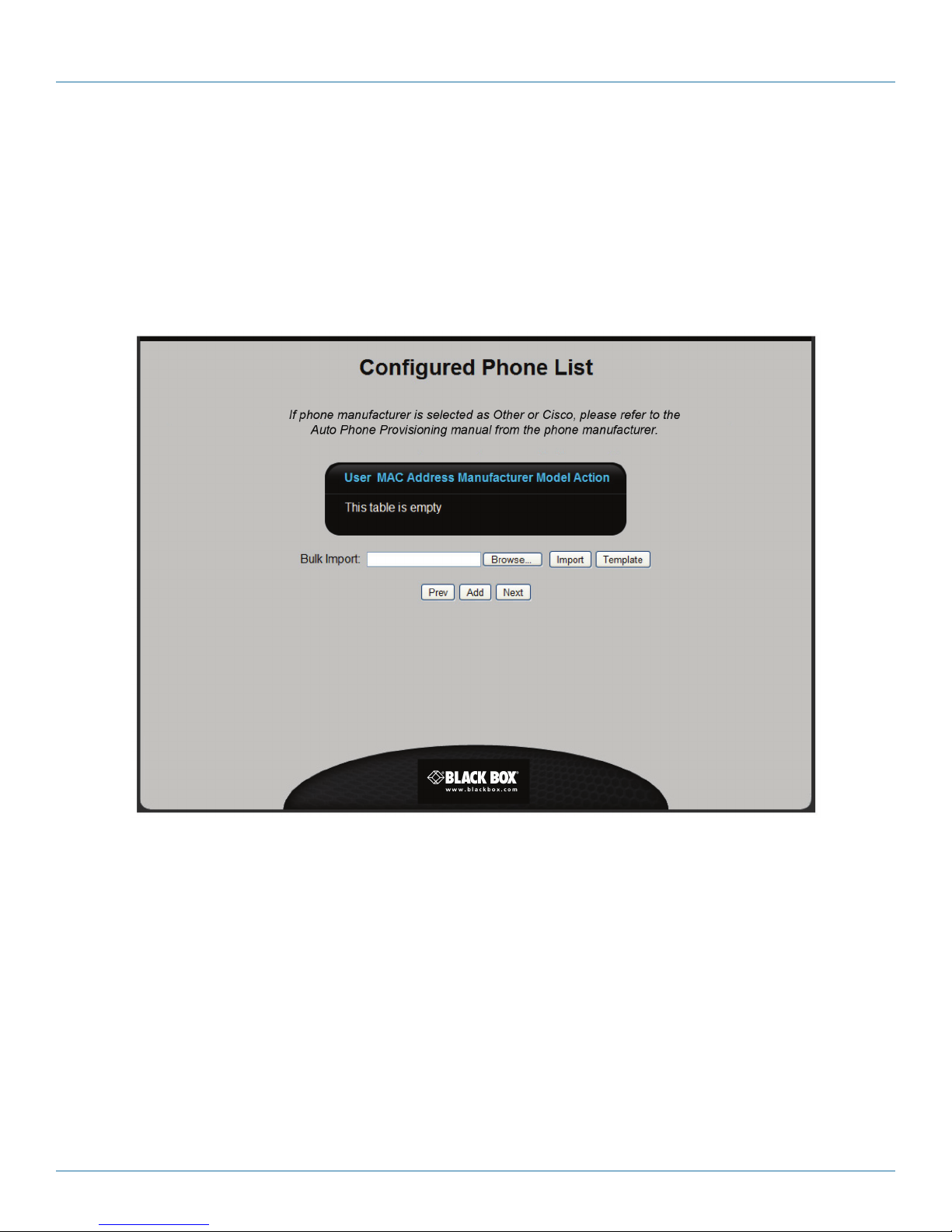
Configured Phone List
This table lists all defined phones. The following information is presented for each phone.
• User: Extension number, first name, and last name of the user assigned to the phone.
• MAC Address: MAC address of the phone.
• Manufacturer: Manufacturer of the phone.
• Model: Model number of the phone.
• Action: Click the appropriate button to Edit or Delete a phone. The Edit button displays the Phone Provisioning page. For details,
see “Adding a phone,” on the next page.
Figure 3-11. Configured Phone List screen.
724-746-5500 | blackbox.com
Page 29
Page 30
724-746-5500 | blackbox.com
Chapter 3: Installation
Adding a phone
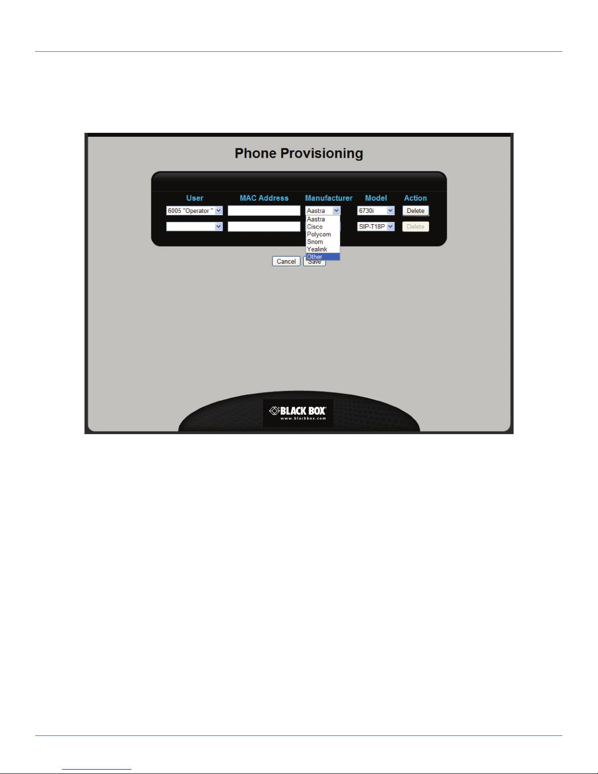
When you click “Add” on the Configured Phone List page, you open the Phone Provisioning page.
Figure 3-12. Phone Provisioning page.
You can define multiple phones on this page. Each time you select a User, a new line is displayed. Configure each phone as
follows. Click “Save” when you are done.
• User: Select an extension/user name from the list. Each user should be bound to only one phone.
• MAC Address: Specify the MAC address of the phone. The MAC address is usually printed on a label on the phone. It is 12
hexadecimal numbers in the format: nn:nn:nn:nn:nn:nn. For example, see “Collect phone information” in Section 3.2.1, STEP 1I.
• Manufacturer: Select the manufacturer of the phone. If you select Cisco, Polycom, or Other, refer to the Auto Phone
Provisioning manual from the phone manufacturer to create a configuration file that can be uploaded and served by the Hybrid
PBX and VoIP Gateway. For more information, see “Automatically provisioning non-supported phones” in the Hybrid PBX and
VoIP Gateway Administrator’s Guide.
• Model: Select the model number of the phone.
• Action: Click “Delete” to remove a phone definition from the list.
Importing phone definitions from a spreadsheet
A quick way to build the phone list is to import definitions from a spreadsheet.
1. Click the “Template” button to download a sample spreadsheet file to your computer.
2. Add phone information to the spreadsheet according to the directions in the file. Save the file when you are done. Do not
change the file extension from .csv. Only .csv files can be uploaded.
Page 30
724-746-5500 | blackbox.com
Page 31
Chapter 3: Installation
3. In the wizard, click “Browse” and then select the spreadsheet file on your computer. Click “OK.”
4. Click “Import” to load the definitions. Each definition is checked during import. If there is a configuration error, then all
definitions are discarded and no phone information is imported.
STEP 3G: Configure VoIP lines.
Use this page to define the VoIP lines that the Hybrid PBX and VoIP Gateway will use to send and receive VoIP calls.
• To define a line, click “Add” and see “Adding a VoIP line,” below.
• When done, click “Next.”
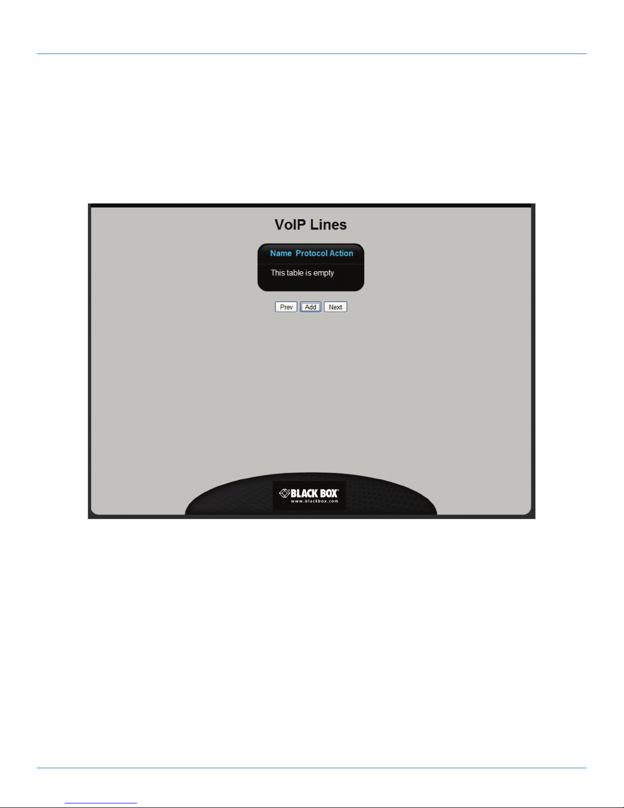
VoIP Lines
This table lists all defined VoIP lines. The following information is presented for each line.
• Name: Name assigned to the line for identification purposes.
• Protocol: Protocol supported by the line: SIP or IAX2.
• Action: Click the appropriate button to Edit or Delete a line. The Edit button displays the VoIP Line page. For details, see
“Adding a VoIP line,” on the next page.
Figure 3-13. VoIP Lines screen.
724-746-5500 | blackbox.com
Page 31
Page 32
724-746-5500 | blackbox.com
Chapter 3: Installation
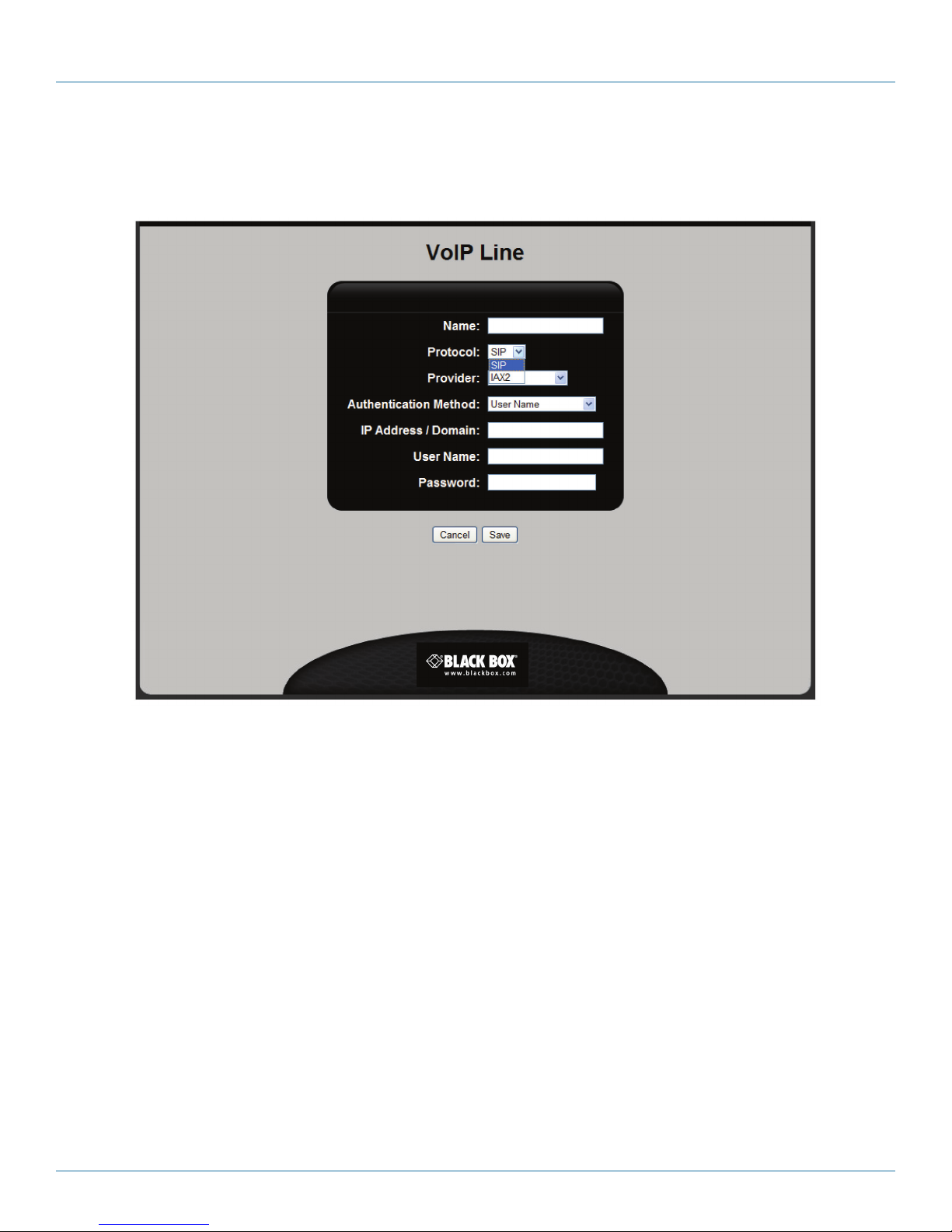
Adding a VoIP line
When you click Add on the VoIP Lines list page, you open the VoIP Line edit page.
Figure 3-14. VoIP Line screen.
Configure the following settings using the information from your VoIP provider. Click “Save” when done.
• Name: Specify a name to identify the line on the Hybrid PBX and VoIP Gateway.
• Protocol: Select the protocol supported by the line: SIP or IAX2.
• Provider: (Only available if SIP is selected for Protocol.) Select your VoIP provider. The Hybrid PBX and VoIP Gateway automatical-
ly defines configuration settings for the following providers:
- babyTEL
- BroadConnect
- Dezmocom
- UnifiedVox
- Unlimited
- SIPGate
- PanOrion
If your provider is not on this list, you will need to create a custom template for it. See “Creating a custom VoIP provider
template” in the “Setting up trunks and lines” chapter in the Hybrid PBX and VoIP Gateway Administrator’s Guide.
®
®
Page 32
724-746-5500 | blackbox.com
Page 33
Chapter 3: Installation
• Authentication Method: If your VoIP provider gave you a username/password, then select Username; otherwise, select IP
address/Domain.
• IP Address/Domain: Specify the IP address of the Hybrid PBX and VoIP Gateway or the name of the domain on which the
Hybrid PBX and VoIP Gateway is located. This address should be assigned to you by your VoIP provider. It is used to establish a
connection with the provider.
• User Name: (Only available if User Name is selected for Authentication Method.) Specify the user name assigned to you by your
provider.
• Password: (Only available if User Name is selected for Authentication Method.) Specify the password assigned to you by your
provider.
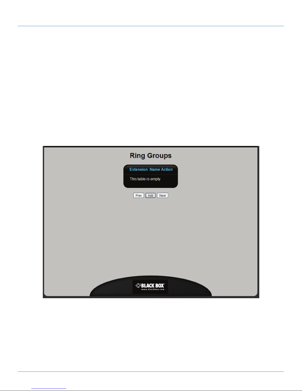
STEP 3H: Configure ring groups.
Use this page to create ring groups. A ring group defines an extension number that when dialed, rings one or more users
simultaneously or in succession. A common use for a ring group is to ring all users in a team (like a sales team), for every
incoming call, or to replace an automated attendant in a small office.
• To define a ring group, click Add and see “Adding a ring group” on the next page.
• When done, click “Next.”
Ring Groups
Lists all defined ring groups. The following information is presented for each ring group.
• Extension: Extension number assigned to the ring group.
• Name: Name assigned to the ring group for identification purposes.
Figure 3-15. Ring Groups screen.
724-746-5500 | blackbox.com
Page 33
Page 34
724-746-5500 | blackbox.com
Chapter 3: Installation
• Action: Click the appropriate button to Edit or Delete a ring group. The Edit button displays the Ring Groups Edit page. For
details, see “Adding a ring group” on the next page.
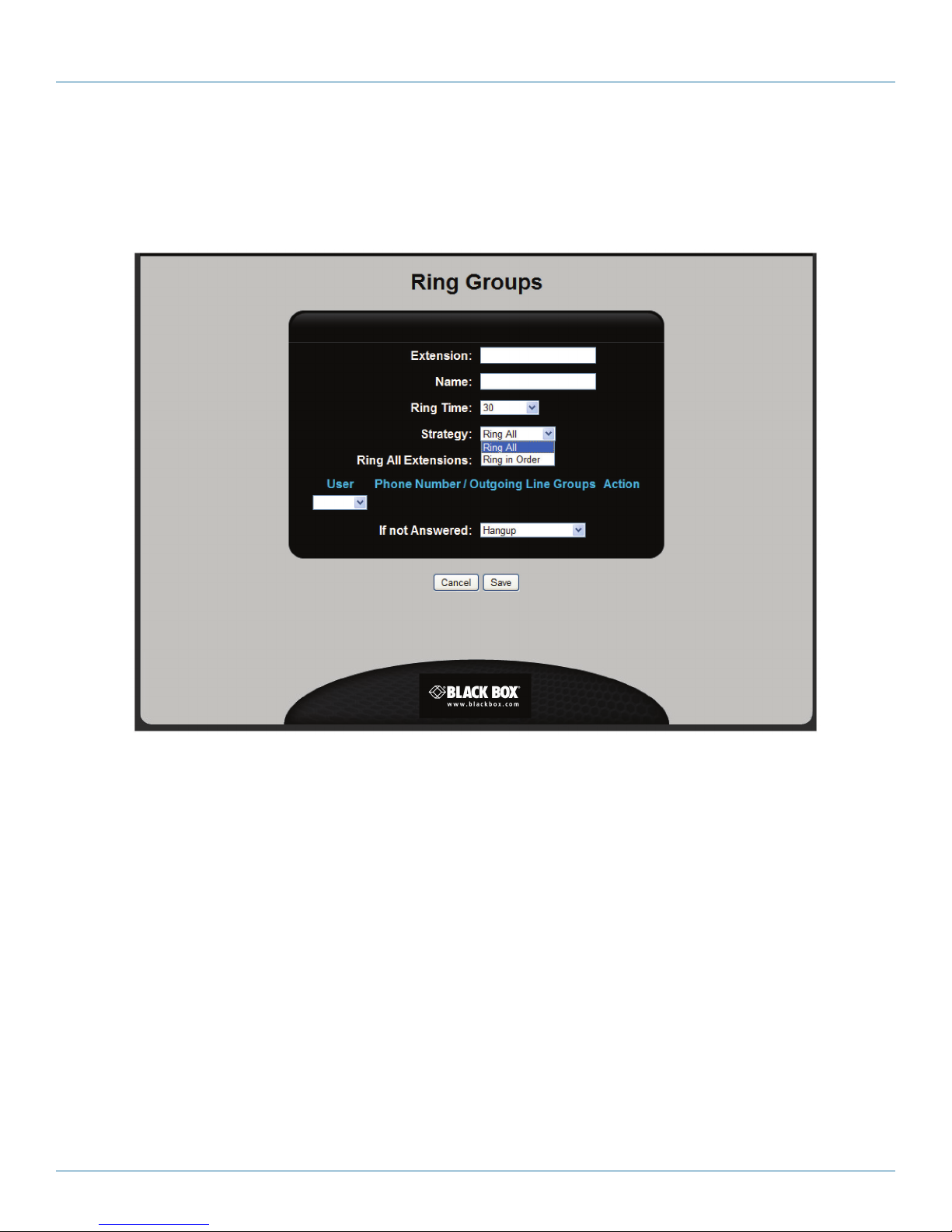
Adding a ring group
When you click “Add” on the Ring Groups List page, you open the Ring Groups Edit page.
Configure the following settings to define a ring group. Click “Save” when done.
• Extension: Specify a unique extension number for the ring group. Extension numbers must be between three and six digits in
length.
• Name: Specify a name to identify the ring group.
• Ring Time: Specify how long phones in the ring group will ring.
• Strategy: Select a ring strategy.
• Ring All: Ring all users in the ring group at the same time.
• Ring in Order: Ring each user in the ring group sequentially in the order they are listed.
• Ring All Extensions: Select this option to make all users defined on the Hybrid PBX and VoIP Gateway part of this ring group.
Ring Group Members
• User: Select a user to add to the ring group.
• Phone Number/Outgoing Line Groups: (Not supported on analog lines) If you select the External option under User, these fields
let you define an external phone number to reach the user. For example, this could be the user’s home phone or cell number.
You also need to select which outgoing line the Hybrid PBX and VoIP Gateway will use to make the call.
Page 34
Figure 3-16. Ring Groups Edit screen.
724-746-5500 | blackbox.com
Page 35
Chapter 3: Installation
• Action: Click “Delete” to remove the user from the ring group.
• If not Answered: Select what happens when a call is not answered by any user in the ring group.
- Goto Voicemail Box: Select the voicemail box for an existing user.
- Go to IVR Menu: This selects the predefined default IVR called 6000 - Sample_IVR.
• Hangup: Terminate the call.
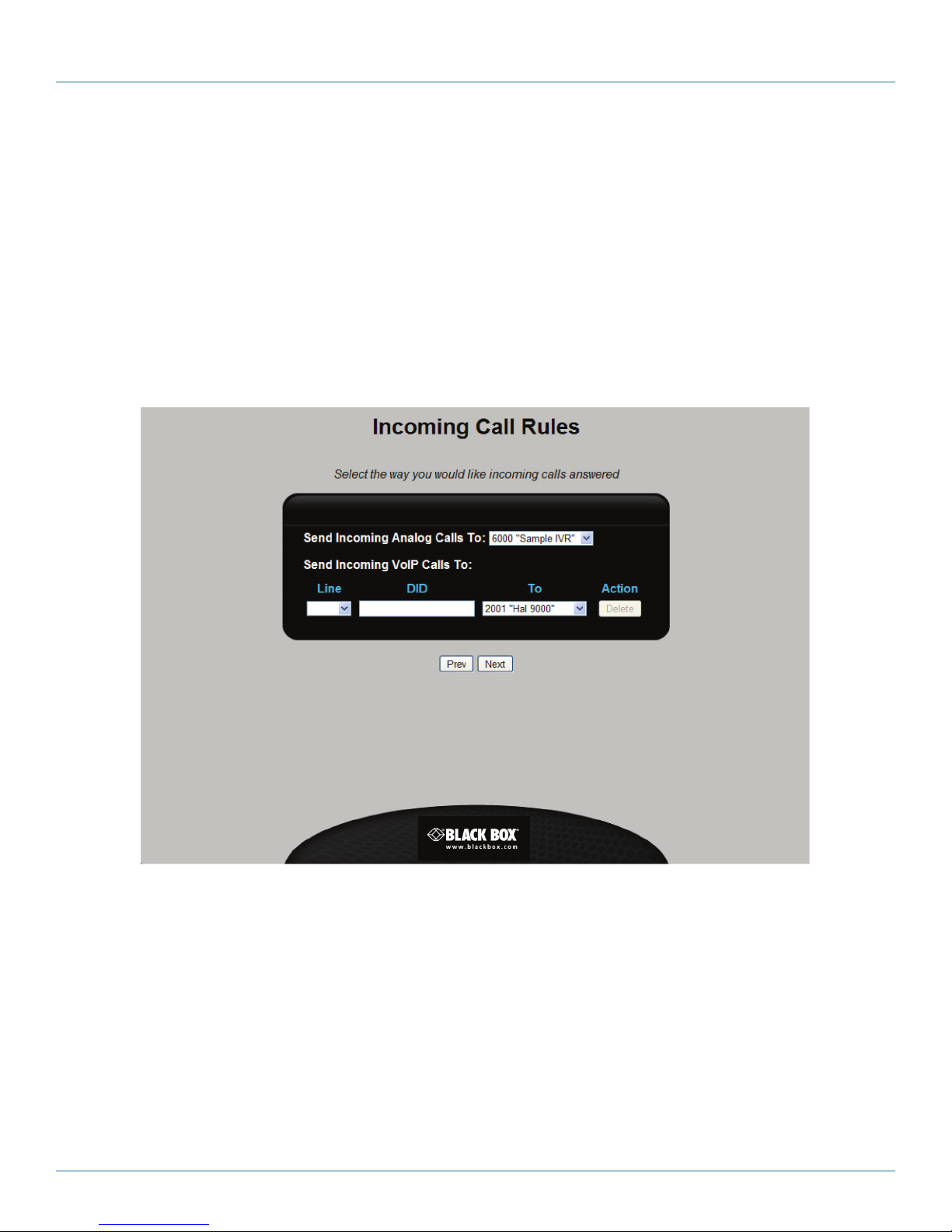
STEP 3I: Configure incoming call rules.
Incoming call rules enable you to define how incoming analog and VoIP calls will be routed to your users. Calls can be routed to a
specific user, a ring group, or an IVR (interactive voice response) menu. An IVR, also known as an automated attendant, lets you
build an interactive voice menu system to handle calls. The Hybrid PBX and VoIP Gateway comes with a pre-defined IVR (called
Sample IVR), which you can assign in the wizard and then later customize.
Configure the settings on this page as described below and then click “Next” to continue.
Send Incoming Analog Calls To
Select the destination to which all incoming analog calls will be routed. These are calls that arrive on the lines connected to the
FXO ports. Available options are:
• User: Select a user that you defined earlier.
• Ring group: Select a ring group that you defined earlier.
Figure 3-17. Incoming Call Rules screen.
724-746-5500 | blackbox.com
Page 35
Page 36

724-746-5500 | blackbox.com
Chapter 3: Installation
• IVR: Only one IVR is available: 6000 “Sample IVR”. This is a pre-defined IVR, which does the following when an incoming call is
received:
1. Answers the line after letting it ring for 2 seconds.
2. Plays a welcome message and then waits 1 second.
3. Plays the “If you know the extension you want to reach” message and then waits 3 seconds for the caller to press a valid
extension number.
4. Repeats the message if no input was received from the caller.
5. Waits 3 seconds for the caller to press a valid extension number.
6. Hangs up if no input was received from the caller.
Once the wizard is complete, you can define other IVRs and assign them to your incoming call rules.
Send Incoming VoIP Calls To
These options are only displayed if a VoIP line is configured.
Choose how incoming calls on each VoIP line will be routed.
• Line: Select a VoIP line.
• DID: If multiple phone numbers are assigned to the VoIP line, your VoIP provider will identify each one with a direct inward
dialing number (DID). Specify the DID number for which you want to route calls.
• To: Select the destination to which all incoming calls will be routed. Available options are:
• User: Select a user that you defined earlier.
• Ring group: Select a ring group that you defined earlier.
• IVR: Only one IVR is available: 6000 “Sample IVR.” This is a pre-defined IVR. For details, see “Send Incoming Analog Calls To”
on the previous page.
• Action: Click “Delete” to remove a rule from the list.
Page 36
724-746-5500 | blackbox.com
Page 37
Chapter 3: Installation
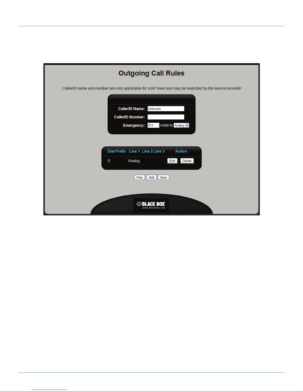
STEP 3J: Configure outgoing call rules.
Outgoing call rules let you define how outbound calls are handled by the Hybrid PBX and VoIP Gateway.
Figure 3-18. Outgoing Call Rules screen.
Configure the settings on this page as described below and then click “Next” to continue.
Default settings for outgoing calls
• CallerID Name: Specify the text that will appear in the caller ID for all calls made through the Hybrid PBX and VoIP Gateway.
• CallerID Number: Specify the phone number that will appear in the caller ID for all calls made through the Hybrid PBX and VoIP
Gateway.
• Emergency: Specify the number to dial for emergency calls and select the line to use.
Outgoing call rules
Use this section to define the rules that determine how a user selects an outbound line when making a call. To add a new rule,
click “Add” and see “Adding an outgoing call rule,” below.
IMPORTANT: By default, an outgoing call rule is automatically defined for Analog calls. To support VoIP calls, you need to add
new rules.
The following information is displayed for each rule:
• Dial Prefix: Number to dial to select the rule.
• Line 1: First line to use. If this line is not available, Line 2 is attempted.
• Line 2: Second line to use. If this line is not available, Line 3 is attempted.
724-746-5500 | blackbox.com
Page 37
Page 38
724-746-5500 | blackbox.com
Chapter 3: Installation
• Line 3: Third line to use. If this line is not available, the message “Please try again later” is played and the call is terminated.
• Action: Click the appropriate button to Edit or Delete a rule. The Edit button displays the Outgoing Call Rules page. For details,
see “Adding an outgoing call rule,” below.
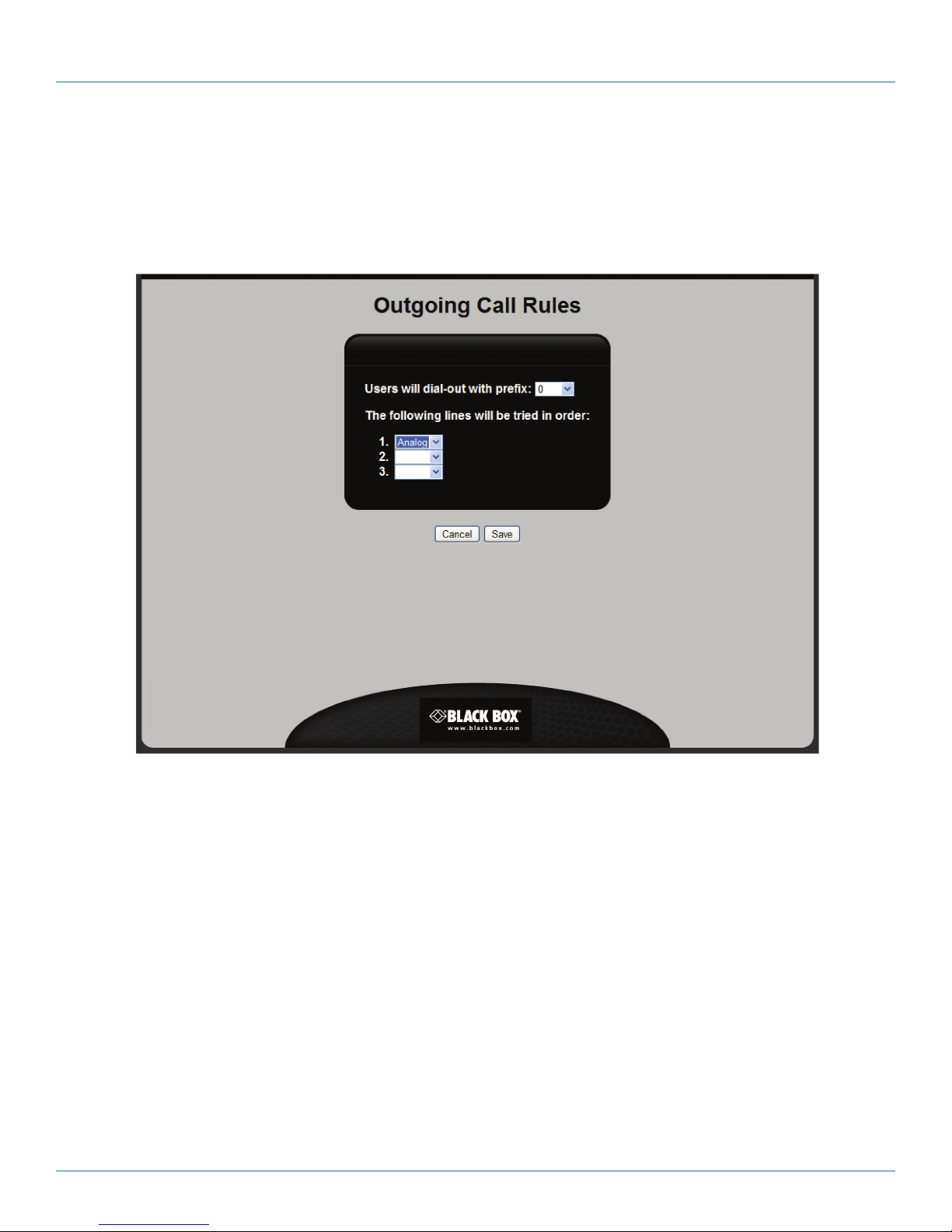
Adding an outgoing call rule
When you click “Add” on the Outgoing Call Rules page, you open the Outgoing Call Rules page.
Configure the following settings to define an outgoing call rule. Click “Save” when done.
• User will dial-out with prefix: Select the number that users must dial to select the rule.
• The following lines will be tried in this order: Select how an outbound line will be assigned.
• Line 1: First line to use. If this line is not available, Line 2 is attempted.
• Line 2: Second line to use. If this line is not available, Line 3 is attempted.
• Line 3: Third line to use. If this line is not available, the message “Please try again later” is played and the call is terminated.
Page 38
Figure 3-19. Outgoing Call Rules screen.
724-746-5500 | blackbox.com
Page 39
Chapter 3: Installation
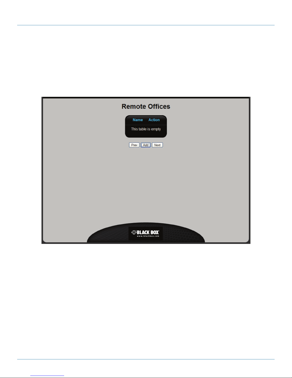
STEP 3K: Configure connections to a remote branch office.
If you have a Hybrid PBX and VoIP Gateway installed at another office, you can set up a connection to it to enable direct
exchange of phone calls using extension numbers and a dialing prefix. For security reasons, we recommend connecting using a
virtual private network (VPN) link.
NOTE: The wizard only supports interconnection of branch offices using static IP addressing.
NOTE: Configuration of intervening network equipment (routers/firewalls) may be required to enable the connection to be
successful.
• To add a remote office, click “Add” and see “Adding a remote office” on the next page.
• When done, click “Next” to continue.
Remote Offices List
The following information is presented for each line:
• Name: Name assigned to the remote office for identification purposes.
• Action: Click the appropriate button to “Edit” or “Delete” an office. The Edit button displays the Remote Office Edit page. For
details, see “Adding a remote office” on the next page.
Figure 3-20. Remote Offices screen.
724-746-5500 | blackbox.com
Page 39
Page 40
724-746-5500 | blackbox.com
Chapter 3: Installation
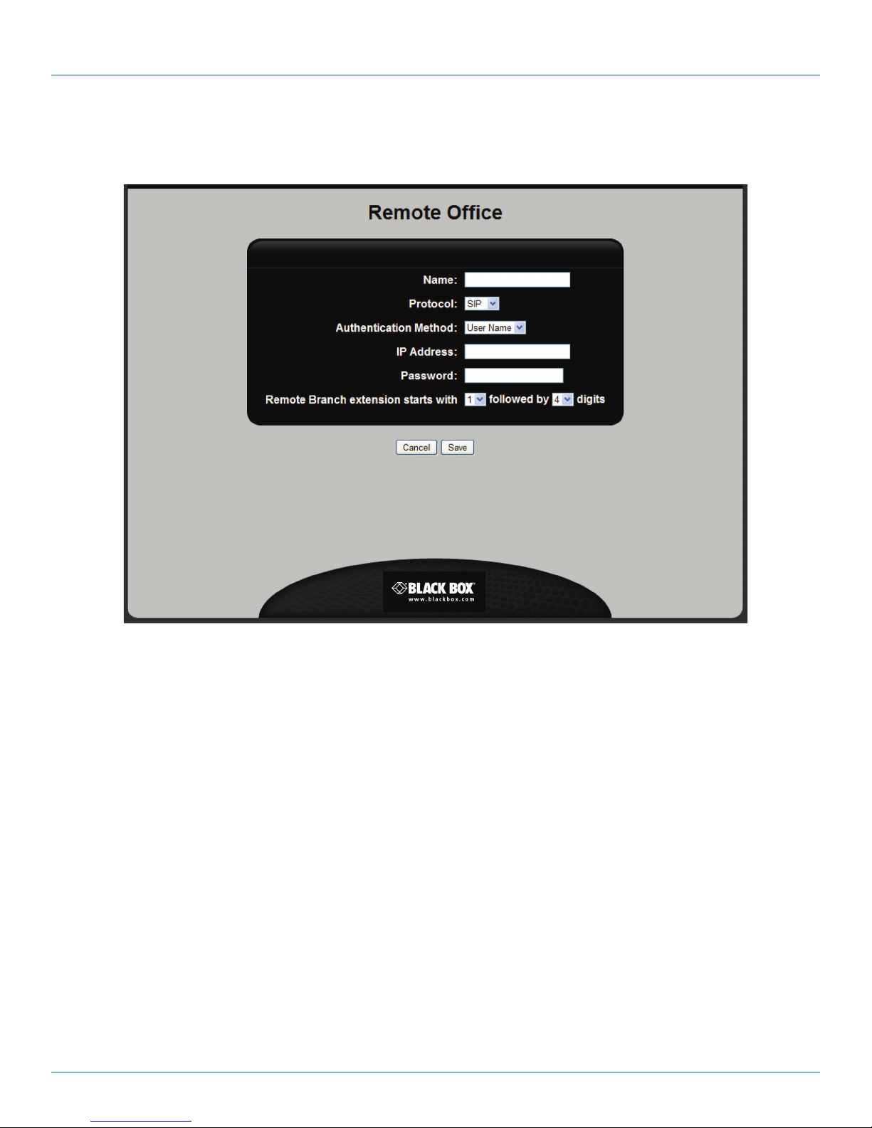
Adding a remote office
When you click “Add” on the Remote Offices list page, you open the Remote Office Edit page.
Figure 3-21. Remote Office Edit page.
Configure the following settings. Click “Save” when done.
• Name: Specify a unique name to identify the remote office.
• Protocol: Select the protocol to use on the connection: SIP or IAX2.
• Authentication method: Select one of the following options:
- User Name: Select this option if the two Hybrid PBX and VoIP Gateways are connected via the Internet. Make sure that Name
and Password are identical on both units.
- IP Address: Select this option if the two Hybrid PBX and VoIP Gateways are in the same office and connected via a LAN, or if
they are in separate offices and connected using a VPN tunnel.
• IP Address: Specify the IP address of the Hybrid PBX and VoIP Gateway WAN port at the remote office. If the port is hidden
behind a router with a firewall or NAT, you need to specify the public IP address of the router, and then configure port forwarding on the router to pass SIP (or IAX2 traffic). See the chapter titled “Remote branch setup” in the Hybrid PBX and VoIP
Gateway Administrator’s Guide.
• Password: Specify a password to protect the connection. The password should be at least 12 characters long and contain a
combination of uppercase /lowercase letters, numbers, and at least one symbol.
• Remote Branch extension starts with X followed by Y digits: Select the prefix (X) that users will dial to reach the branch office,
then select the number of digits used to identify extensions at the branch office (Y).
Page 40
724-746-5500 | blackbox.com
Page 41
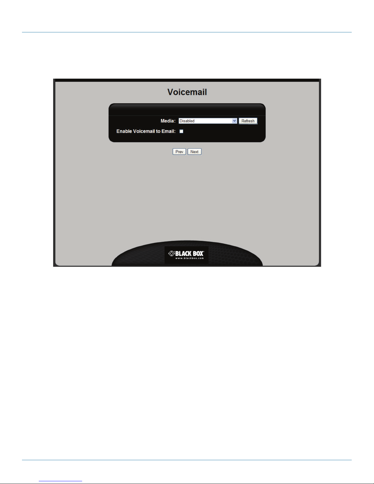
STEP 3L: Configure voicemail settings.
In this step, you configure voicemail settings.
Chapter 3: Installation
Figure 3-22. Voicemail screen.
Configure the following settings. Click “Next” to continue.
• Media: Select the auxiliary memory device that will store voicemail. If you did not install auxiliary memory earlier, you can install
a USB flash drive now and click “Refresh” to discover it.
NOTE: If the memory device needs to be formatted, a Format button will appear. Click it to initialize the device.
NOTE: If no memory is installed, the Hybrid PBX and VoIP Gateway will store voicemail in its internal memory. See “Obtain auxilia-
ry
memory” in Section 3.2.1, STEP 1C.
• Enable Voicemail to Email: If you enable this feature, voicemail messages can be sent to users as wav files (if enabled for a user’s
account).
724-746-5500 | blackbox.com
Page 41
Page 42
724-746-5500 | blackbox.com
Chapter 3: Installation
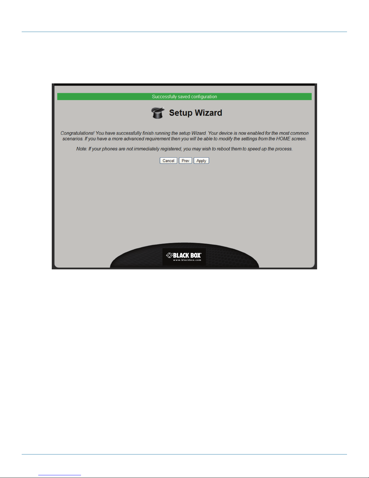
STEP 3M: Finish the wizard and apply your settings.
Click “Apply” to complete the wizard and apply the configuration settings. The Hybrid PBX and VoIP Gateway will restart.
Figure 3-23. Setup Wizard screen.
Page 42
724-746-5500 | blackbox.com
Page 43
Chapter 3: Installation
3.2.4 STEP 4: Test your installation
This section describes a few tests you can do to ensure that the key features of the Hybrid PBX and VoIP Gateway are properly
configured.
STEP 4A: Connect to the command center.
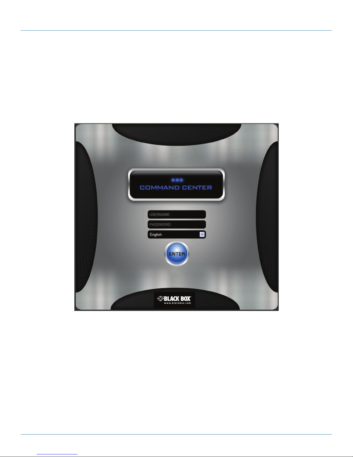
Specify http//192.168.1.2 in the address bar of your browser and press “Enter.” (If you changed the address of the LAN ports,
specify the new address instead.)
The command center Login page opens.
Specify the username and password you set in the Setup Wizard, choose your language of operation, and click “Enter.”’ The
command center Status page opens.
Figure 3-24. Command Center screen.
724-746-5500 | blackbox.com
Page 43
Page 44
724-746-5500 | blackbox.com
Chapter 3: Installation
STEP 4B: Verify your configuration.
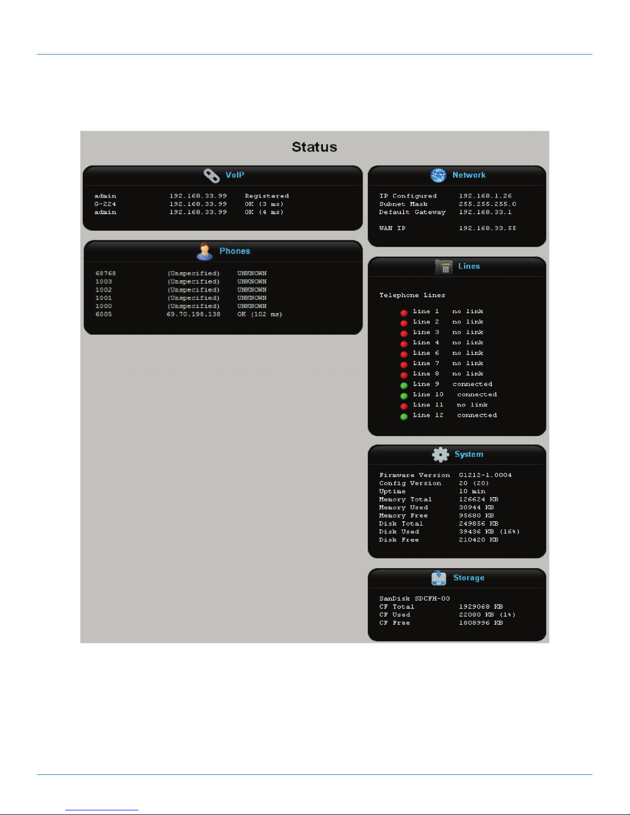
The Status page shows the current status of the Hybrid PBX and VoIP Gateway. For example:
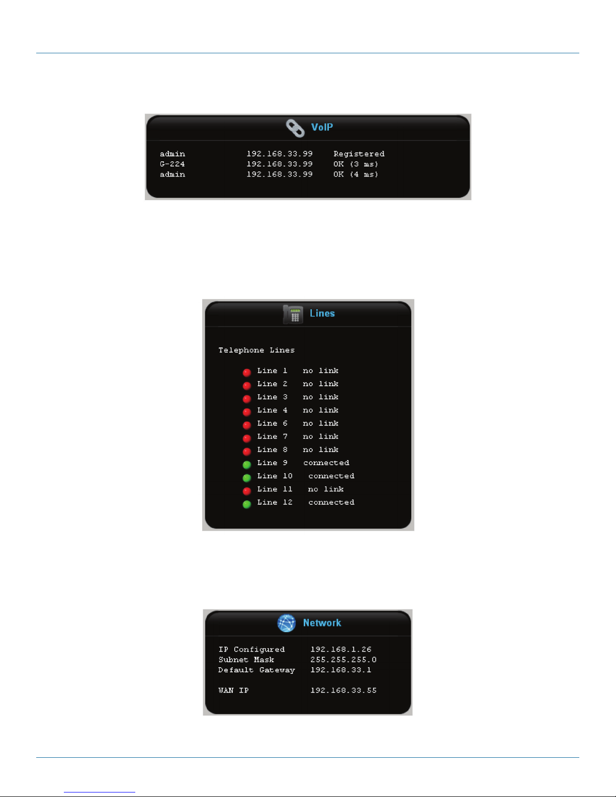
VoIP
If you have VoIP lines, check the VoIP box to verify their status. For each line, you should see an IP address and a status value of
OK (xx ms), where xx indicates how long it takes the Hybrid PBX and VoIP Gateway to communicate with the VoIP carrier.
Page 44
Figure 3-25. Status screen.
724-746-5500 | blackbox.com
Page 45
Chapter 3: Installation
Figure 3-26. VoIP Status screen.
Analog lines
Check the “Lines” box to verify the status of your analog phone lines. For each line, you should see a green light and a status
value of “connected.”
Network connections
Shows the addresses assigned to the LAN and WAN ports (if defined).
Figure 3-28. LAN and WAN Addresses Assigned screen.
Figure 3-27. Lines Status screen.
724-746-5500 | blackbox.com
Page 45
Page 46
724-746-5500 | blackbox.com
Chapter 3: Installation
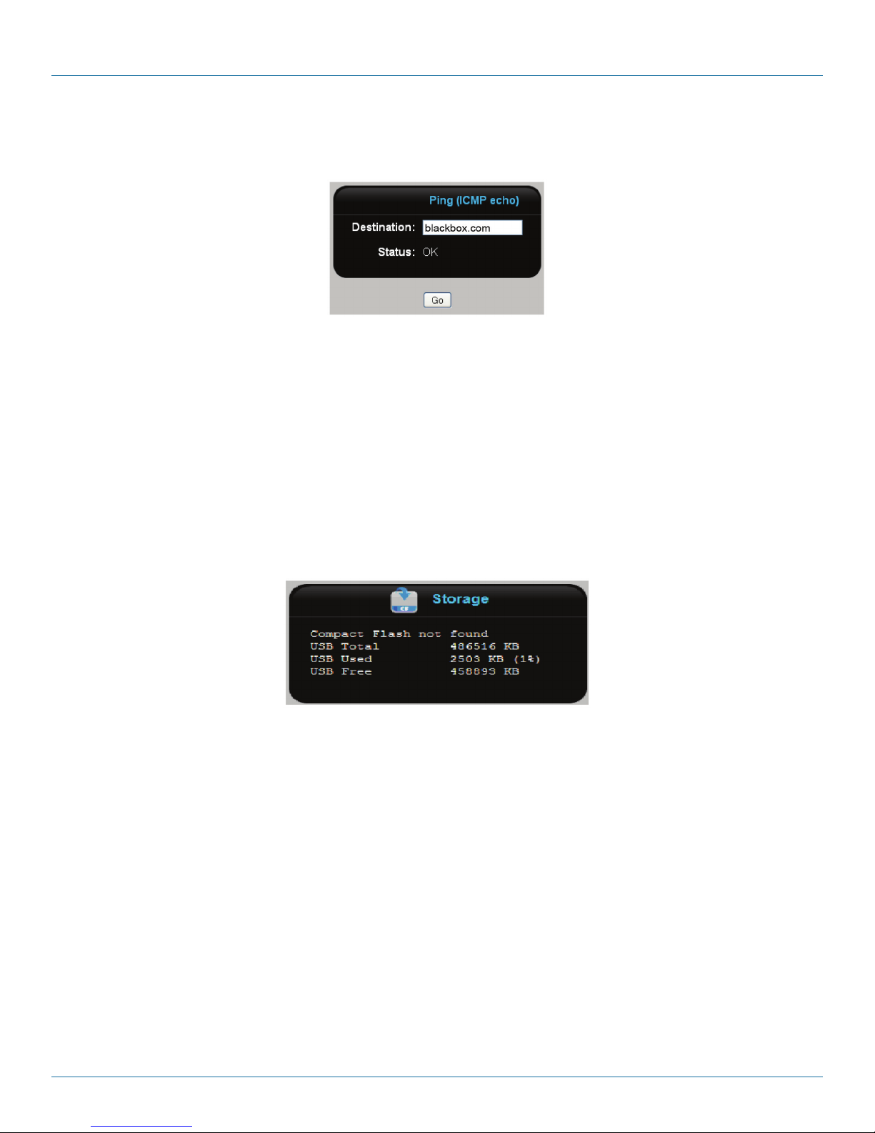
To see if your connection to the Internet is working:
1. Select Diagnostics > Diagnostics > Ping.
Figure 3-29. Ping screen.
2. Specify the address of a site on the Internet. For example: blackbox.com
3. Click “Go.”
• If Status displays “OK,” then the connection is working.
• If Status displays “No response,” then select “System > Network > Network” and make sure that the Default Gateway and DNS
server are set to the correct values.
Storage
Check the Storage box to verify the status of auxiliary storage.
• For a USB flash drive you should see memory totals.
Figure 3-30. Memory totals screen.
Page 46
724-746-5500 | blackbox.com
Page 47
Chapter 3: Installation
STEP 4C: Connect a SIP phone and make a call.
This test only works if you used the wizard to:
• Configure a phone from Aastra, SNOM, or Yealink.
• Configure the Hybrid PBX and VoIP Gateway as the DHCP server on your network.
Do the following:
1. Plug the phone into your LAN, or directly into Port 1, 2, or 3.
2. Power on the phone. When ready, it will show the user name and extension number.
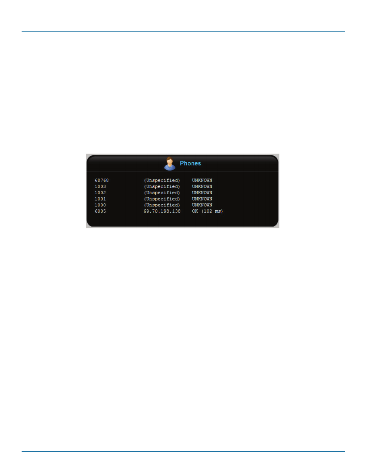
3. Check the “Phones” box on the Status page. The phone should appear in the list with a status of “OK” (xx ms). In this
example, Phone 6005 is ready for use:
Figure 3-31. Phones Ready for Use screen.
4. Dial a call and wait for it to connect.
5. Hang up.
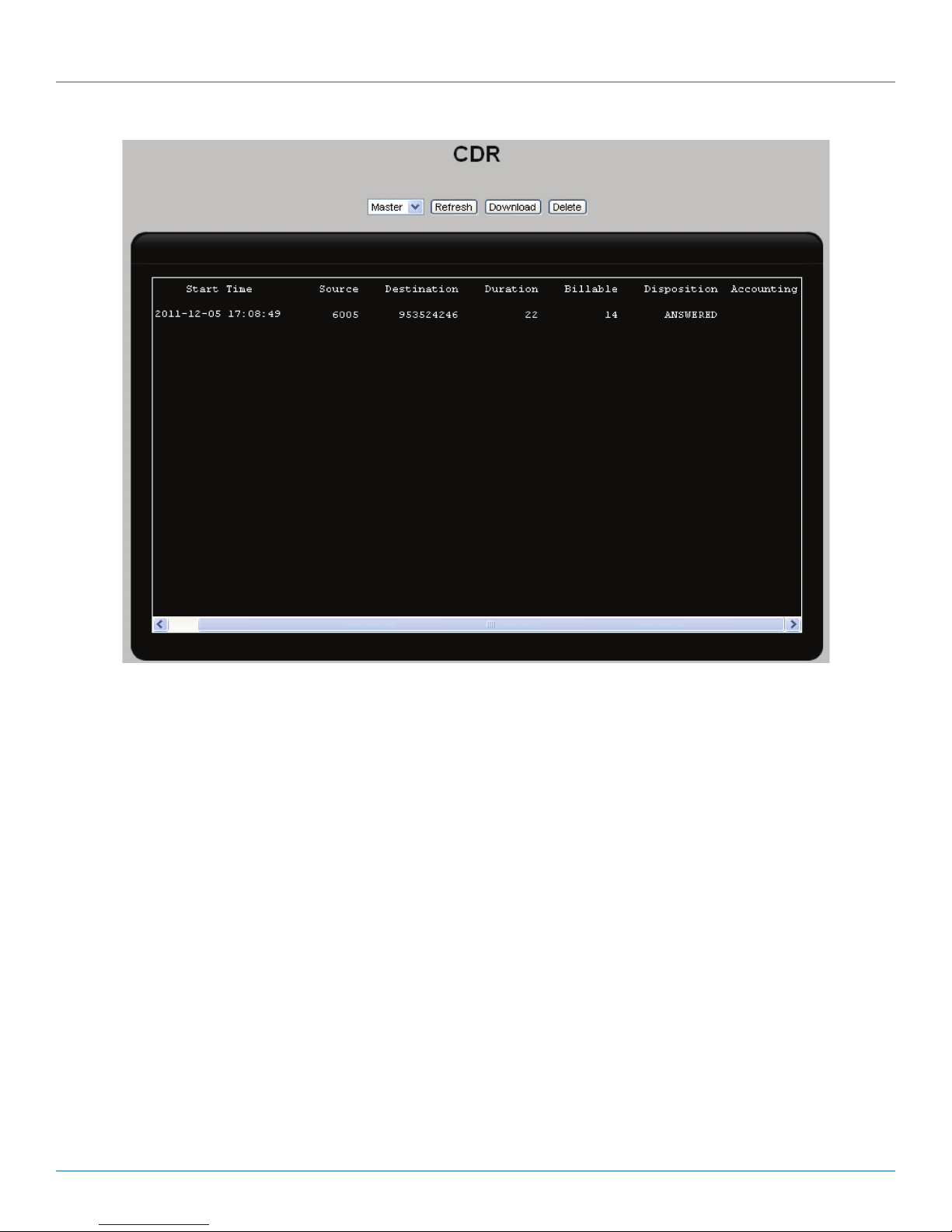
6. Select System > CDR. You should see a record for the call.
724-746-5500 | blackbox.com
Page 47
Page 48
724-746-5500 | blackbox.com
Chapter 3: Installation
Figure 3-32. CDR screen.
STEP 4D: Receive a call.
The following procedure explains how to test for call reception:
Assumptions
• The SIP phone that will receive the call is at extension 6005, and is connected/registered to the Hybrid PBX and VoIP Gateway.
• An analog line or VoIP line is active,
• Incoming calls are redirected to Sample_IVR.
To test inbound calling
1. Make an inbound call to the Hybrid PBX and VoIP Gateway (via an analog line number or VoIP DID number).
2. The Hybrid PBX and VoIP Gateway answers the call and plays the "Thank you for calling” message.
3. Dial extension 6005.
4. The SIP phone at extension 6005 rings.
5. Answer the call.
6. Hang up the call.
7. Select System > CDR. You should see a record for the call.
Page 48
724-746-5500 | blackbox.com
Page 49

Chapter 3: Installation
STEP 4E: Record voicemail.
The following procedure explains how to test voicemail.
Assumption
• Two SIP phones, one on extension 6005, and the other on extension 6006, are connected/registered to the Hybrid PBX and
VoIP Gateway.
To test voicemail
1. Pick up the phone at 6005 and dial 6006.
2. When the phone at 6006 rings, do not answer the call.
3. Listen to the Unavailable message and then leave a voicemail message after the beep.
4. The Message Waiting Indicator (MWI) light on the 6005 phone should turn on.
5. Pick up the phone at 6005 and dial 6050, or press the “envelope” button to check the voicemail.
6. The voicemail system prompts for the voicemail password of the user. The default voicemail password is 1234. One voicemail
message should be available.
STEP 4F: Voicemail to email.
The following procedure explains how to test the voicemail to e-mail feature.
Assumptions
• Two SIP phones, one on extension 6005, and the other on extension 6006, are connected/registered to the Hybrid PBX and
VoIP Gateway.
• Both extensions have valid e-mail addresses defined under their accounts.
• SMTP settings were properly configured in the wizard.
To test voicemail to e-mail
1. Pick up the phone at 6005 and dial 6006.
2. When the phone at 6006 rings, do not answer the call.
3. Listen to the Unavailable message and then leave a voicemail message after the beep.
4. The Message Waiting Indicator (MWI) light on the 6005 phone should turn on.
5. Select Diagnostics > Logs > Email Log to see that an e-mail was successfully sent without errors.
6. Check the target mailbox to see if the e-mail arrived with a voicemail attachment.
3.2.5 STEP 5: What’s next
STEP 5A: Create a custom VoIP template
If you selected Other as your VoIP provider, you will need to create a custom template for it, and then assign it to the VoIP lines
you added. For details, see the Hybrid PBX and VoIP Gateway Administrator’s Guide.
• To create the template, see Creating a custom VoIP provider template in the “Setting up trunks and lines” chapter in the Hybrid
PBX and VoIP Gateway Administrator’s Guide.
• To modify a VoIP line:
1. Select PBX > Trunks/Lines > Trunks/ Lines.
724-746-5500 | blackbox.com
Page 49
Page 50

724-746-5500 | blackbox.com
Chapter 3: Installation
2. In the list, click “Edit” for the VoIP line.
3. Set the value for Provider to the new template.
4. Click “Save.”
5. Click “Apply Configuration.”
STEP 5B: Configure port forwarding.
If the connection to the Internet is behind a router or firewall, it will also block access to the VoIP lines. In this case, you will have
to configure port forwarding on any intervening router/firewall. By default, you need to forward UDP ports 5060 and 10000 to
20000. These ports can be changed by selecting System > Network > SIP/RTP in the command center. For details, see Step 3:
Configure port forwarding in the Setting up trunks and lines chapter in the Hybrid PBX and VoIP Gateway Administrator’s Guide.
STEP 5C: Customize the sample IVR.
If you assigned the sample IVR to your incoming call rules, you will likely want to customize it, or replace it with an IVR or your
own design. See the section Configuring incoming call rules in the “Call management” chapter in the Hybrid PBX and VoIP
Gateway Administrator’s Guide.
STEP 5D: Record voicemail messages and set passwords.
Users can record their unavailable/name directory message by dialling 6050. They can also change their voicemail password from
there as well.
Page 50
724-746-5500 | blackbox.com
Page 51

NOTES
724-746-5500 | blackbox.com
Page 51
Page 52

Black Box Tech Support: FREE! Live. 24/7.
Tech support the
way it should be.
Great tech support is just 30 seconds away at 724-746-5500 or blackbox.com.
About Black Box
Black Box provides an extensive range of networking and infrastructure products. You’ll find everything from cabinets and racks
and power and surge protection products to media converters and Ethernet switches all supported by free, live 24/7 Tech support
available in 30 seconds or less.
© Copyright 2012. Black Box Corporation. All rights reserved.
IPBX424 Installation Guide, version 1
724-746-5500 | blackbox.com
 Loading...