

Page 1
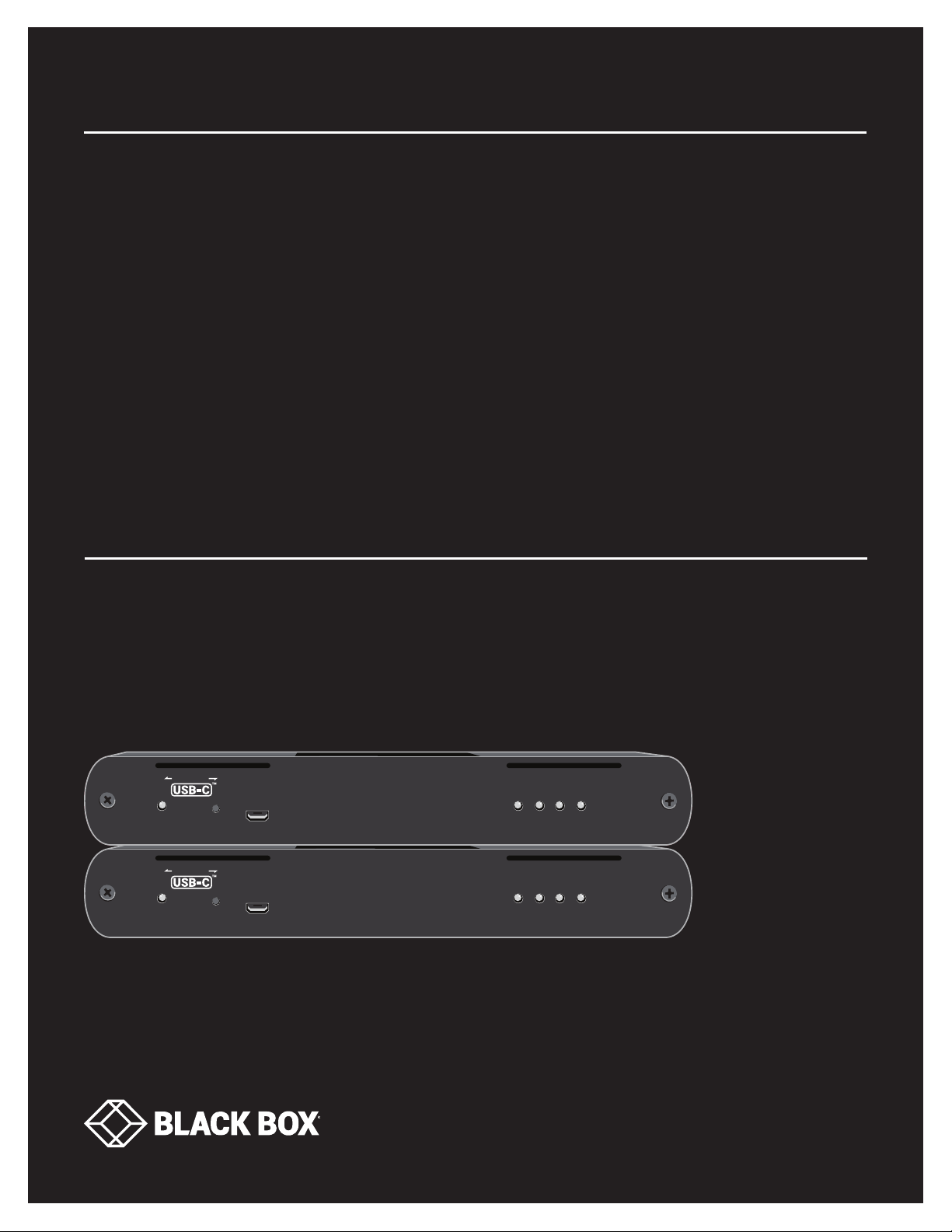
USER MANUAL
ICU544A
U S B 3.1
FIBER
EXTENDER
24/7 TECHNICAL SUPPORT AT 1.877.877.2269 OR VISIT BLACKBOX.COM
EXTREME
Power
Power
EXTREME
Mode
Mode
Config
Config
Status Link
Status Link
USB2 USB3
USB2 USB3
Page 2
NEED HELP?
LEAV E TH E TEC H TO US
LIVE 24/7
TABLE OF CONTENTS
TECHNICAL
SUPPORT
1. 8 7 7. 877.226 9
QUICK START GUIDE ......................................................................................................................................................................... 4
PRODUCT OPERATION AND STORAGE........................................................................................................................................... 7
1. SPECIFICATIONS ........................................................................................................................................................................... 8
2. OVERVIEW ...................................................................................................................................................................................... 9
2.1 Introduction ...............................................................................................................................................................................................9
2.2 Features .................................................................................................................................................................................................... 9
2.3 What’s Included ........................................................................................................................................................................................9
2.4 Hardware Description ............................................................................................................................................................................10
2.4.1 Local Extender ..................................................................................................................................................................................................10
2.4.2 Remote Extender .............................................................................................................................................................................................12
3. INSTALLATI O N ............................................................................................................................................................................ 14
3.1 Requirements for Installing the Extender .............................................................................................................................................14
3.2 Fiber Optic Cabling Guidelines ..............................................................................................................................................................14
3.3 Preparing Your Site ................................................................................................................................................................................14
3.4 Installing the Local Extender ................................................................................................................................................................. 14
3.5 Connecting the Local Extender to the Remote Extender.................................................................................................................... 15
3.6 Installing the Remote Extender ............................................................................................................................................................. 15
3.7 Checking the Installation ....................................................................................................................................................................... 15
3.8 Connecting a USB Device ...................................................................................................................................................................... 15
3.9 Compatibility ........................................................................................................................................................................................... 15
3.10 Optional Ethernet Pass-through Connection ..................................................................................................................................... 16
4. OPTIONAL USB EXTENDER MOUNTING OPTIONS ................................................................................................................. 17
4.1 Option 1: USB Extender Mounting Kit ................................................................................................................................................... 17
4.2 Option 2: USB Extender Direct Surface Mounting (Using Your Own Hardware) ..............................................................................18
5. TROUBLESHOOTING ................................................................................................................................................................... 20
5.1 Troubleshooting Tips .............................................................................................................................................................................20
5.2 Contacting Black Box Technical Support.............................................................................................................................................23
APPENDIX A. REGULATORY INFORMATION ................................................................................................................................ 24
A.1 FCC Radio Frequency Interference Statement Warning ..................................................................................................................... 24
A.2 CE Statement .........................................................................................................................................................................................24
A.3 IC Statement ..........................................................................................................................................................................................24
A.4 WEEE Statement .................................................................................................................................................................................... 24
2
1. 8 77. 8 77. 2 26 9 BLACKBOX.COM
Page 3

NEED HELP?
LEAV E TH E TEC H TO US
LIVE 24/7
TABLE OF CONTENTS
TECHNICAL
SUPPORT
1. 8 7 7. 877.226 9
APPENDIX B. TECHNICAL GLOSSARY .......................................................................................................................................... 25
APPENDIX C. DISCLAIMER/TRADEMARKS ................................................................................................................................. 26
C.1 Disclaimer ...............................................................................................................................................................................................26
C.2 Trademarks Used in this Manual .......................................................................................................................................................... 26
1. 8 77. 8 77. 2 26 9 BLACKBOX.COM
3
Page 4
NEED HELP?
LEAV E TH E TEC H TO US
LIVE 24/7
QUICK START GUIDE
Before you get started, ensure that all the drivers required for your USB device(s) are installed.
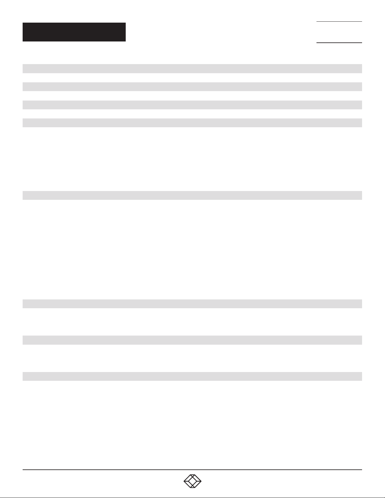
STEP 1. Place extenders where desired and connect the fiber cable to the Link ports (LC) on the Local and Remote Extenders.
Local Extender (back view) Remote Extender (back view)
TECHNICAL
SUPPORT
1. 8 7 7. 877.226 9
Link
24V 1AUSBLAN
Link
(Multimode Fiber Cable not included)
Maximum 656 ft. (200 m) MMF Cable
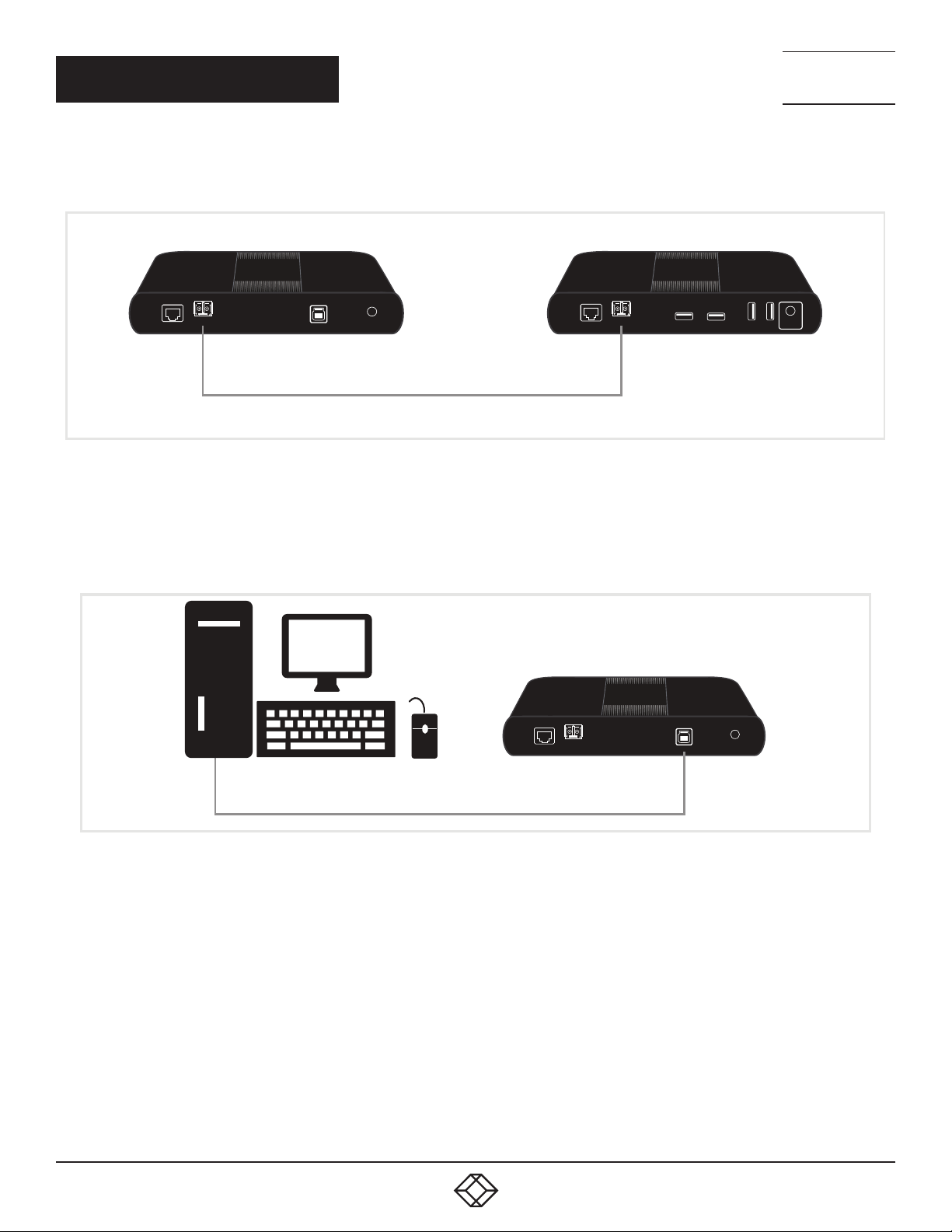
STEP 2. Connect the Local Extender to the computer’s USB 3 port using the included USB cable.
Local Extender (back view)
Link
PC
24V 2.71AUSB USB USB USBLAN
24V 1AUSBLAN
4
1. 8 77. 8 77. 2 26 9 BLACKBOX.COM
Page 5
QUICK START GUIDE
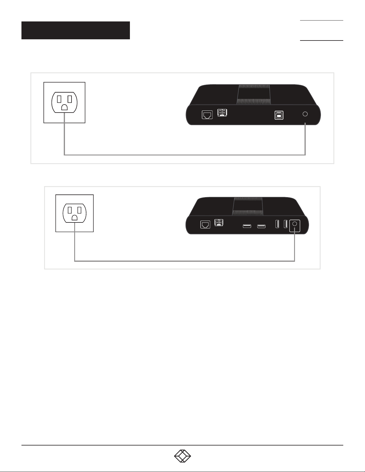
STEP 3. Power the Local Extender with the included 24 V, 1 A AC adapter and tighten the locking ring.
Local Extender (back view)
NEED HELP?
LEAV E TH E TEC H TO US
LIVE 24/7
TECHNICAL
SUPPORT
1. 8 7 7. 877.226 9
Link
STEP 4. Power the Remote Extender with the included 24 V, 2.71 A AC adapter and tighten the locking ring.
Remote Extender (back view)
Link
24V 1AUSBLAN
24V 2.71AUSB USB USB USBLAN
1. 8 77. 8 77. 2 26 9 BLACKBOX.COM
5
Page 6
QUICK START GUIDE
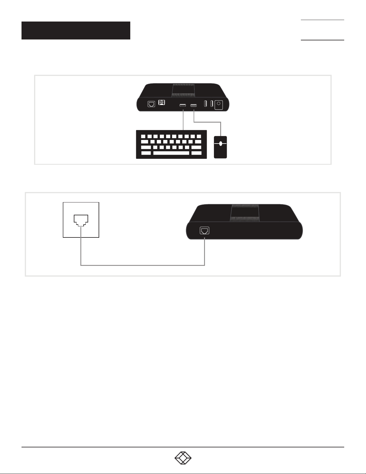
STEP 5. Attach the USB device(s) to the Remote Extender.
Remote Extender (back view)
NEED HELP?
LEAV E TH E TEC H TO US
LIVE 24/7
TECHNICAL
SUPPORT
1. 8 7 7. 877.226 9
Link
24V 2.71AUSB USB USB USBLAN
STEP 6. Optional: Connect Local and Remote Extender LAN ports to a network or device as necessary.
Local/Remote Extender LAN Port
LAN
6
1. 8 77. 8 77. 2 26 9 BLACKBOX.COM
Page 7

NEED HELP?
LEAV E TH E TEC H TO US
LIVE 24/7
PRODUCT OPERATION AND STORAGE
TECHNICAL
SUPPORT
1. 8 7 7. 877.226 9
Please read and follow all instructions provided with this product, and operate for the intended use only.
Do not attempt to open the product casing as this may cause damage and will void the warranty. Use only the power supply provided with
this product. When not in use, the product should be stored in a dry location between -4 to +158° F (-20 to +70° C).
1. 8 77. 8 77. 2 26 9 BLACKBOX.COM
7
Page 8

CHAPTER 1: SPECIFICATIONS
TABLE 1-1. SPECIFICATIONS
SPECIFICATION DESCRIPTION
Range
Point-to-Point Up to 656 ft. (200 m) over OM3 multimode fiber optic cable
USB Device Support
Maximum Throughput 5 Gbps
Traffic Types All Traffic Types
Dev ice Ty pes All Device Types
Maximum Number of Devices and/or Hubs Up to 30 devices
Local Extender
USB Connector (1) USB 3.1 Gen 1 Type B
Link Connector (1) pair of fiber LC
Network Passthrough (1) RJ-45 LAN
Dimensions 1.3"H x 9.1"W x 5.4"D (3.3 x 23.2 x 13.7 cm)
Enclosure Material Black Anodized Aluminum
Power Supply
Remote Extender
USB Connector (4) USB 3.1 Gen 1 Type B
Link Connector (1) pair of fiber LC
Network Passthrough (1) RJ-45 LAN
Dimensions 1.3"H x 9.1"W x 5.4"D (3.3 x 23.2 x 13.7 cm)
Enclosure Material Black Anodized Aluminum
Available Current Up to 1.2 A (6 W) to each USB port
Power Supply
Environmental
Operating Temperature Range 32 to 122° F (0 to 50° C)
Storage Temperature Range -4 to +158° F (-20 to +70° C)
Operating Humidity 20 to 80% relative humidity, noncondensing
Storage Humidity 10 to 90% relative humidity, noncondensing
Compliance
EMC FCC Class B, CE Class B
Environmental RoHS2 (CE)
Input: 10 0–240 VAC ;
Output: 24-VDC, 1 A
Input: 10 0–240 VAC ;
Output: 24-VDC, 2.71 A
NEED HELP?
LEAV E TH E TEC H TO US
LIVE 24/7
TECHNICAL
SUPPORT
1. 8 7 7. 877.226 9
8
1. 8 77. 8 77. 2 26 9 BLACKBOX.COM
Page 9

NEED HELP?
LEAV E TH E TEC H TO US
LIVE 24/7
CHAPTER 2: OVERVIEW
TECHNICAL
SUPPORT
1. 8 7 7. 877.226 9
2.1 INTRODUCTION
This guide provides product information for the USB 3.1 Fiber Extender 4-Port (ICU544A), installation instructions and troubleshooting
guidelines. The instructions in this guide assume a general knowledge of computer installation procedures, familiarity with cabling
requirements, and some understanding of USB devices.
The ICU544A enables users to extend beyond the standard 16-foot (5-meter) cable limit for USB peripheral devices. With the Extender,
USB device(s) can be located up to 656 feet (200 meters) from the computer. The Extender is composed of two individual units: the local
extender and remote extender.
CAUTION: The local and remote extenders may be hot to the touch during operation.
2.2 FEATURES
The USB 3.1 Extender incorporates ExtremeUSB-C™ technology, enabling users to extend USB 3.1 beyond the standard 9.8-foot
(3-meter) cable limit for USB 3.1 peripheral devices. This extender system is composed of two individual units, the Local Extender
and the Remote Extender, and has the following key features:
Up to 656 feet (200 meters) of extension when directly connected over OM3 multimode fiber optic cable
Support for new USB 3.1 Gen 1/2 host controllers and devices (up to 5 Gbps)
Support for all device USB types
Backwards compatible to USB 2.0 devices
NOTE: The USB 3.1 Extender includes the ExtremeUSB-C™ suite of features:
Transparent USB extension supporting USB 3, 2 and 1
True plug-and-play; no software drivers required
Works with all major operating systems: Windows
NOTE: The USB 3.1 Extender only works with OM3 multimode fiber or higher grade cable.
2.3 WHAT’S INCLUDED
Your package should include the following items. If anything is missing or damaged, contact Black Box Technical Support
at 877-877-2269 or [email protected].
(1) Local Extender
(1) Remote Extender
(1) USB 3.1 Gen. 1 Cable
(1) Local Extender 24-VDC, 1-A International Power Adapter
(1) Remote Extender, 24-VDC, 2.71-A International Power Adapter
(2) Country-Specific Power Cords
®
, macOS™, Linux® and Chrome OS™
1. 8 77. 8 77. 2 26 9 BLACKBOX.COM
9
Page 10
NEED HELP?
LEAV E TH E TEC H TO US
LIVE 24/7
CHAPTER 2: OVERVIEW
2.4 HARDWARE DESCRIPTION
TECHNICAL
SUPPORT
1. 8 7 7. 877.226 9
2.4.1 LOCAL EXTENDER
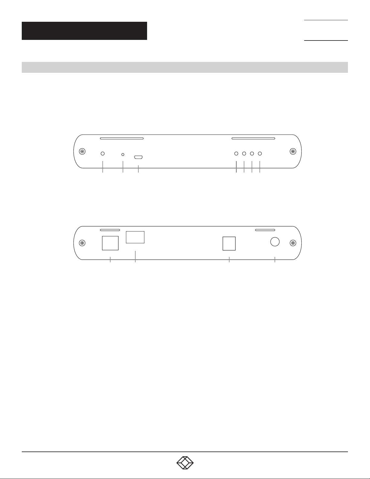
The local extender connects to the computer using a standard USB 3.1 Gen. 1 cable (included). Power for the local extender is provided
by the included 24-V, 1-A adapter.
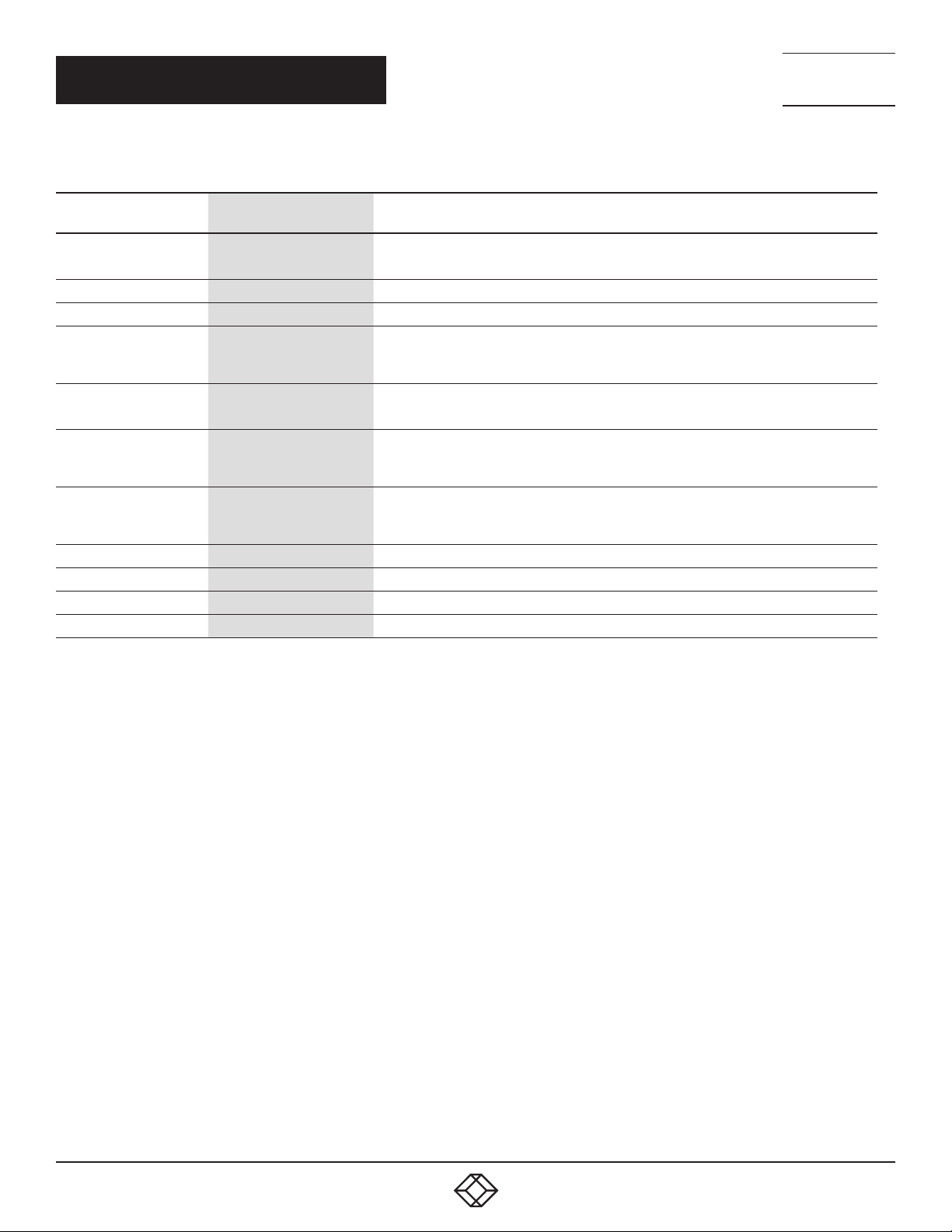
Figures 2-1 and 2-2 show the front and back of the Local Extender. Table 2-1 describes its components.
Config
1
2
3
FIGURE 2-1. LOCAL EXTENDER, FRONT VIEW
Link
LAN 24V 1AUSB
8
9
FIGURE 2-2. LOCAL EXTENDER, BACK VIEW
USB 2 USB 3ModePower LinkStatus
5 6 7
4
10 11
10
1. 8 77. 8 77. 2 26 9 BLACKBOX.COM
Page 11
CHAPTER 2: OVERVIEW
TABLE 2-1. LOCAL EXTENDER COMPONENTS
NEED HELP?
LEAV E TH E TEC H TO US
LIVE 24/7
TECHNICAL
SUPPORT
1. 8 7 7. 877.226 9
NUMBER IN FIGURE 2-1
OR 2-2
1 Power LED (Green)
2 Mode button Reserved for manufacturer use.
3 Config port Reserved for manufacturer use.
4 Status LED
5 Link LED (Green)
6 USB 2 LED
7 USB 3 LED
8 LAN Port (100/1000 Mbps) Ethernet passthrough channel connects to a network or Ethernet device.
9 Link Port (LC) Extension link Duplex LC fiber optic transceiver port.
10 USB Host Port USB 3 Type B receptacle used to connect Local Extender to USB 3 Host computer.
11 DC Power Port Locking connector for the included power adapter – accepts 24-VDC, 1-A.
COMPONENT DESCRIPTION
LED turns on when DC power is supplied to the unit.
LED is off when no power is supplied by the AC adapter.
LED is SOLID ON when system is functioning normally. LED BLINKS when system is
booting OR to indicate a temperature warning in unison with the LINK, USB 2, and USB 3
LEDs.
LED is SOLID ON when Local Extender is linked to an opposite Remote Extender.
LED is OFF when there is no connection between the Local and Remote Extenders.
LED is SOLID ON when an active USB 2 connection is established through the extender
system. LED BLINKS when the USB 2 connection is suspended/asleep. LED is OFF when
no USB 2 connection is detected.
LED is SOLID ON when an active USB 3 connection is established through the extender
system. LED BLINKS when the USB 3 connection is suspended/asleep. LED is OFF when
no USB 3 connection is detected.
1. 8 77. 8 77. 2 26 9 BLACKBOX.COM
11
Page 12
NEED HELP?
LEAV E TH E TEC H TO US
LIVE 24/7
CHAPTER 2: OVERVIEW
TECHNICAL
SUPPORT
1. 8 7 7. 877.226 9
2.4.2 REMOTE EXTENDER
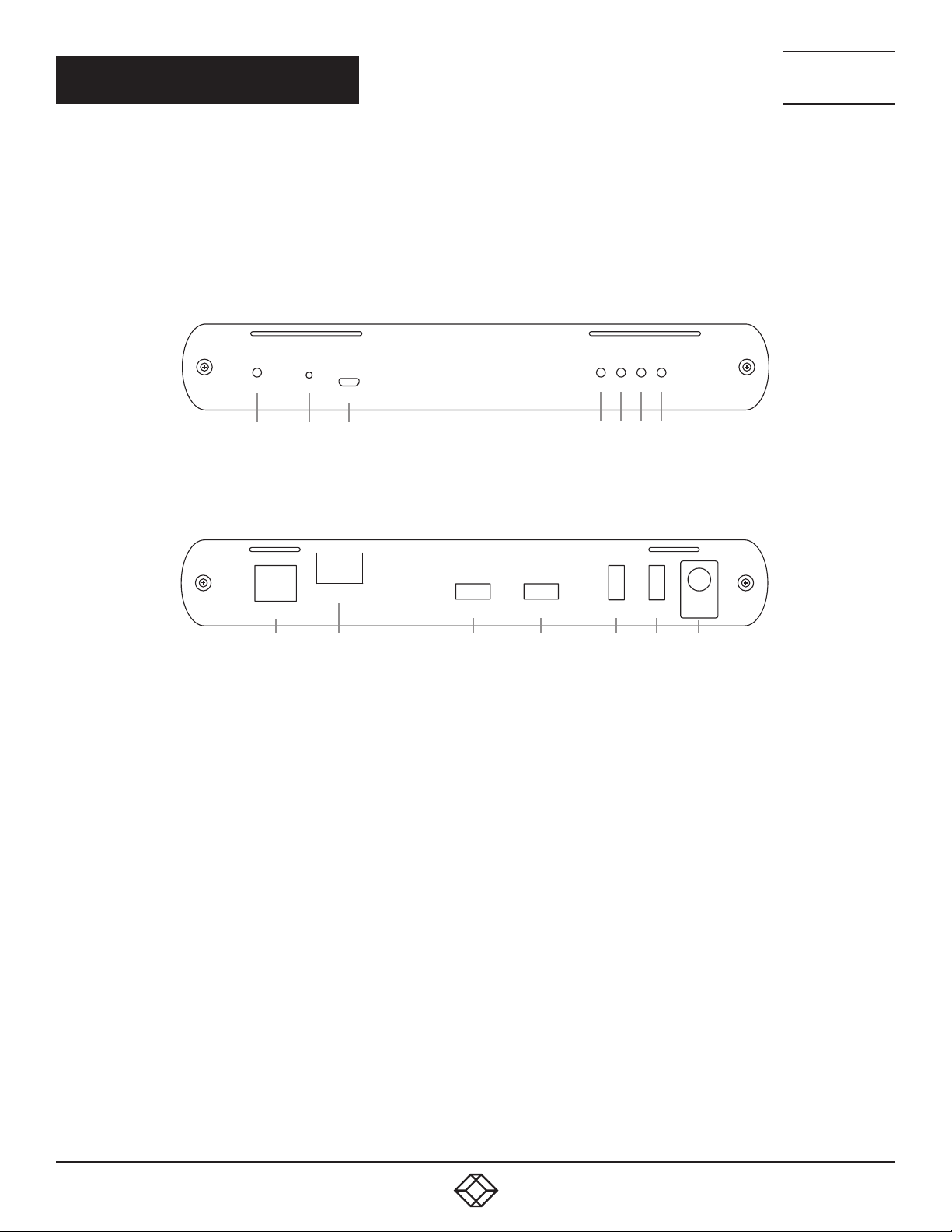
The Remote Extender provides USB 3.1 Type A ports for standard USB devices and allows you to connect up to four USB devices directly.
Additional devices may be connected by attaching up to three USB hubs to the Remote Extender. The Remote Extender is powered by an
external 24-VAC, 2.71-A adapter, supplying up to 1.2 Amp per USB port.
Figures 2-3 and 2-4 show the front and back of the Remote Extender. Table 2-2 describes its components.
Config
5 6 7
1
2
3
4
FIGURE 2-3. REMOTE EXTENDER, FRONT VIEW
Link
LAN USBUSB USB USB
8
9
10
10
10 10
FIGURE 2-4. REMOTE EXTENDER, BACK VIEW
USB 2USB 3ModePower LinkStatus
24V 2.71A
11
12
1. 8 77. 8 77. 2 26 9 BLACKBOX.COM
Page 13
NEED HELP?
LEAV E TH E TEC H TO US
LIVE 24/7
CHAPTER 2: OVERVIEW
TECHNICAL
SUPPORT
1. 8 7 7. 877.226 9
TABLE 2-2. REMOTE EXTENDER COMPONENTS
NUMBER IN FIGURE 2-3 OR 2-4 COMPONENT DESCRIPTION
1 Power LED (Green)
2 Mode button Reserved for manufacturer use.
3 Config port Reserved for manufacturer use.
4 Status LED
5 Link LED (Green)
6 USB 2 LED
7 USB 3 LED
8
9 Link Port (LC) Extension link Duplex LC fiber optic transceiver port.
10 (4) USB Device Ports Accepts all USB devices.
11 DC Power Port Locking connector for the included power adapter – accepts 24-VDC, 2.71-A.
LAN Port
(100/1000 Mbps)
LED turns on when DC power is supplied to the unit.
LED is off when no power is supplied by the AC adapter.
LED is SOLID ON when system is functioning normally. LED BLINKS when system is
booting OR to indicate a temperature warning in unison with the LINK, USB 2, and USB 3
LEDs.
LED is SOLID ON when Remote Extender is linked to an opposite Local Extender.
LED is OFF when there is no connection between the Local and Remote Extenders.
LED is SOLID ON when an active USB 2 connection is established through the extender
system. LED BLINKS when the USB 2 connection is suspended/asleep. LED is OFF when
no USB 2 connection is detected.
LED is SOLID ON when an active USB 3 connection is established through the extender
system. LED BLINKS when the USB 3 connection is suspended/asleep. LED is OFF when
no USB 3 connection is detected.
Ethernet passthrough channel connects to a network or Ethernet device.
1. 8 77. 8 77. 2 26 9 BLACKBOX.COM
13
Page 14
NEED HELP?
LEAV E TH E TEC H TO US
LIVE 24/7
CH AP TE R 3: I NS TAL LAT IO N
3.1 REQUIREMENTS FOR INSTALLING THE EXTENDER
To complete the installation, you will also require the following items that are not included with this system:
USB compatible computer (host computer) with a USB compliant operating system
USB compatible device(s)
OM3 fiber optic cabling
3.2 FIBER OPTIC CABLING GUIDELINES
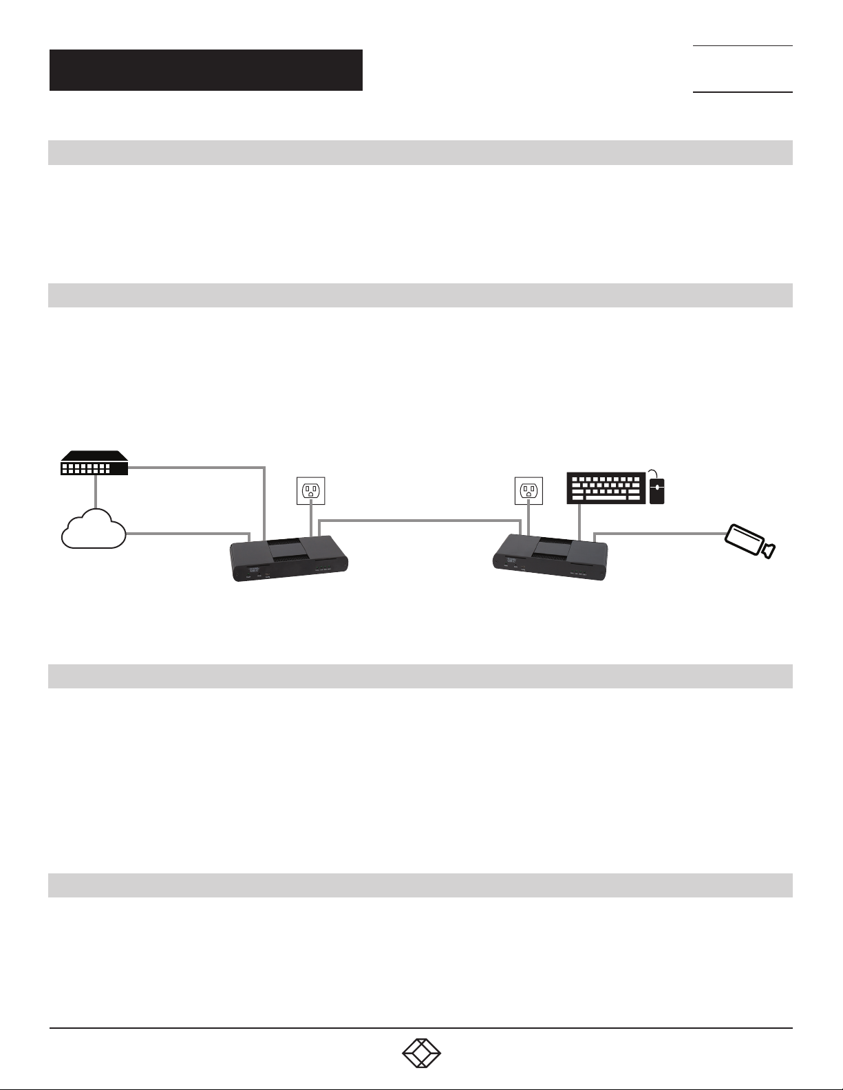
The Local and Remote Extenders are interconnected by fiber optic cabling. Duplex multimode fiber cabling is required for the extenders
for extending up to 656 feet (200 meters) using 50/125-μm OM3 grade cable. The cabling subsystem must provide a duplex connection
with crossover, and must be terminated with Duplex LC connectors at both ends.
TECHNICAL
SUPPORT
1. 8 7 7. 877.226 9
Host
USB Cable
USB Devices
LAN
Optional
Network
Connections
Up to 656 ft. (200 m) over MMF
Local Extender Remote Extender
USB 3-2-1
Optional
Network
Connections
IP Control
FIGURE 3-1. TYPICAL INSTALLATION
3.3 PREPARING YOUR SITE
Before installing the USB 3.1 Extender, you will need to prepare your site:
1. Place the computer where desired and set it up.
2. Locate your USB device(s) within the cable-length of the computer. If not, adjust the location of your device(s) and/or computer
accordingly.
3. If you are using surface cabling, the USB 3.1 Extender supports a maximum distance of 656 feet (200 meters) over OM3 multimode
fiber.
4. If using premise cabling, ensure compatible fiber optic cabling is installed between the two locations and does not to exceed the
specified distance.
3.4 INSTALLING THE LOCAL EXTENDER
1. Place the Local Extender near the computer.
2. Assemble the 24-V, 1-A power adapter and country-specific power cord together and connect them into a suitable AC outlet.
3. Connect the supplied USB 3.1 Gen cable between the Local Extender host port and a USB 3 port on the host computer.
14
1. 8 77. 8 77. 2 26 9 BLACKBOX.COM
Page 15

CH AP TE R 3: I NS TAL LAT IO N
3.5 CONNECTING THE LOCAL EXTENDER TO THE REMOTE EXTENDER
With Surface Cabling:
1. Plug one end of the fiber optic cable (not included) into the Link port on the Local Extender.
2. Plug the other end of the fiber optic cable into the Link port on the Remote Extender.
With Premise Cabling:
1. Plug one end of a fiber optic patch cord (not included) into the Link port on the Local Extender.
2. Plug the other end of the patch cord into the fiber optic information outlet near the host computer.
3. Plug one end of the second fiber optic patch cord (not included) into the Link port on the Remote Extender.
4. Plug the other end of the patch cord into the fiber optic information outlet near the USB device.
3.6 INSTALLING THE REMOTE EXTENDER
1. Place the Remote Extender near the USB device(s).
2. Assemble the power adapter and country-specific power cord together and connect them into a suitable AC outlet.
3. Connect the 24-V, 2.71-A power adapter to the Remote Extender.
NEED HELP?
LEAV E TH E TEC H TO US
LIVE 24/7
TECHNICAL
SUPPORT
1. 8 7 7. 877.226 9
3.7 CHECKING THE INSTALLATION
1. On the Local and Remote Extenders, check that the Power, Status, Link, USB 2 and USB 3 LEDs are on. If the Link LEDs are permanently
off, then the cabling between the Local and Remote Extender may not be installed properly or is defective.
2. For Windows users (XP, 7, 8, 8.1, 10), open Device Manager to confirm that the extender system has been installed correctly. Expand
the entry for Universal Serial Bus controllers by clicking the “+” sign. If the extender system has been installed correctly, you should find
two separate instances of “Generic SuperSpeed USB Hub” listed.
NOTE: To open Device Manager in Windows 7: Open the Start Menu, right click on “Computer” then select: Manage >> Device Manager
NOTE: To open Device Manager in Windows 8, 8.1 or 10: Right click the Start Menu and then select: Device Manager
3. For macOS users, open the System Profiler to confirm that the extender system has installed correctly. In the left-hand column under
Hardware, select “USB” and inspect the right-hand panel. If the extender has been installed correctly, you should find it listed as two
separate instances of “Hub” under the USB SuperSpeed Bus.
NOTE: To open System Profiler in macOS: Open the Finder, select Applications, then open the Utilities folder and double click on the
System Profiler icon.
4. If the extender system is not detected correctly or fails to detect, please consult the Troubleshooting section in this guide.
3.8 CONNECTING A USB DEVICE
1. Install any software required to operate the USB device. Refer to the documentation for the USB device, as required.
2. Connect the USB device to the device port on the Remote Extender.
3. Check that the device is detected and installed properly in the operating system.
3.9 COMPATIBILITY
The USB 3.1 Extender complies with USB 2.0 and USB 3.1 Gen 1 specifications governing the design of USB devices. However, there
is no guarantee that all USB devices or hosts will be compatible as there are a number of different characteristics that may impact the
operation of USB devices over extended distances.
1. 8 77. 8 77. 2 26 9 BLACKBOX.COM
15
Page 16
NEED HELP?
LEAV E TH E TEC H TO US
LIVE 24/7
CH AP TE R 3: I NS TAL LAT IO N
3.10 OPTIONAL ETHERNET PASSTHROUGH CONNECTION
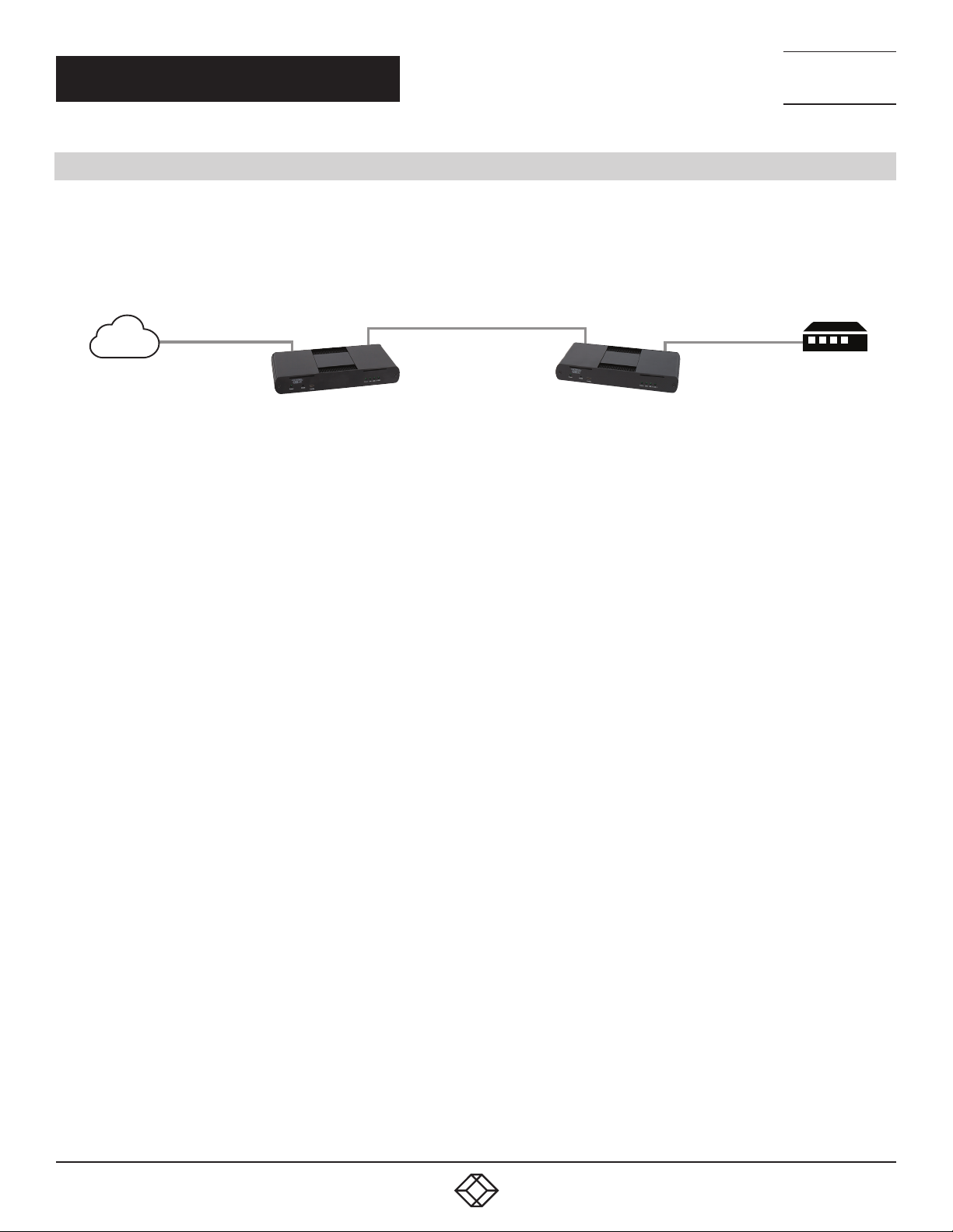
The Extender offers a 100/1000 Mbps Ethernet pass through connection that can be used for a variety of purposes including:
Connecting network devices
Providing remote network access to the same location as the Remote Extender
Leveraging existing cabling to provide USB 3-2-1 connectivity without losing network connectivity
TECHNICAL
SUPPORT
1. 8 7 7. 877.226 9
LAN
Up to 100m
over CAT 6a/7
Local Extender Remote Extender
Up to 656 ft. (200 m) over MMF
Up to 100m
over CAT 6a/7
Network Device
FIGURE 3-2. ETHERNET PASSTHROUGH APPLICATION
Connect any network device or access port into the RJ-45 socket label “LAN” using up to 328 feet (100 meters) of standard CAT5e, 6 or 7
cabling.
16
1. 8 77. 8 77. 2 26 9 BLACKBOX.COM
Page 17
NEED HELP?
LEAV E TH E TEC H TO US
LIVE 24/7
CHAPTER 4: MOUNTING OPTIONS
The bottom of the enclosure features four convenient pre-drilled holes for optional mounting. Based on your requirements, choose from
two available mounting options:
1. USB Extender Mounting Kit (Purchased separately order USB Mounting Kit - Black (part number IC400MK)
2. USB Extender Direct Surface Mounting (Using your own hardware, stencil provided)
4.1 OPTION 1: USB EXTENDER MOUNTING KIT
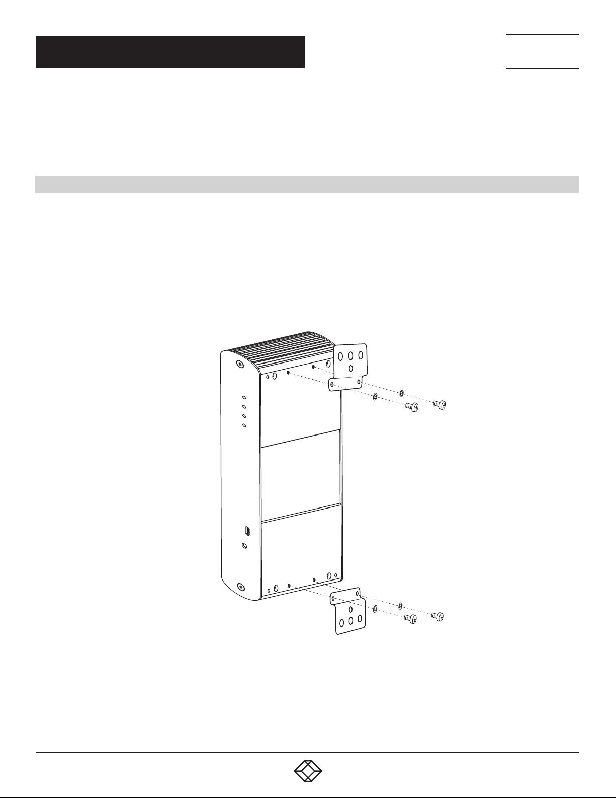
Contents:
(2) mounting brackets
(4) M3 locking washers
(4) M3 x 10-mm Phillips screws
(1) Mounting bracket installation guide (see diagram)
NOTE: One kit is required to mount per Local Extender or Remote Extender
Using a Phillips screwdriver, in the order as illustrated below, fasten and secure the provided screws, locking washers and brackets into
place.
TECHNICAL
SUPPORT
1. 8 7 7. 877.226 9
FIGURE 4-1. MOUNTING KIT
Once the bracket mounting is secured onto the extender, it is ready for mounting onto a surface.
NOTE: You will need to provide your own screws to secure the extender using the available slots on each bracket.
1. 8 77. 8 77. 2 26 9 BLACKBOX.COM
17
Page 18
NEED HELP?
LEAV E TH E TEC H TO US
LIVE 24/7
CHAPTER 4: MOUNTING OPTIONS
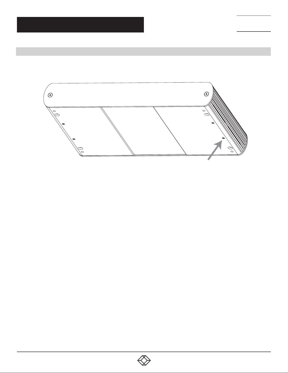
4.2 OPTION 2: USB EXTENDER DIRECT SURFACE MOUNTING (USING YOUR OWN HARDWARE)
The bottom of the enclosure features four pre-drilled holes for optional surface mounting.
TECHNICAL
SUPPORT
1. 8 7 7. 877.226 9
Mounting hole
FIGURE 4-2. DIRECT SURFACE MOUNTING
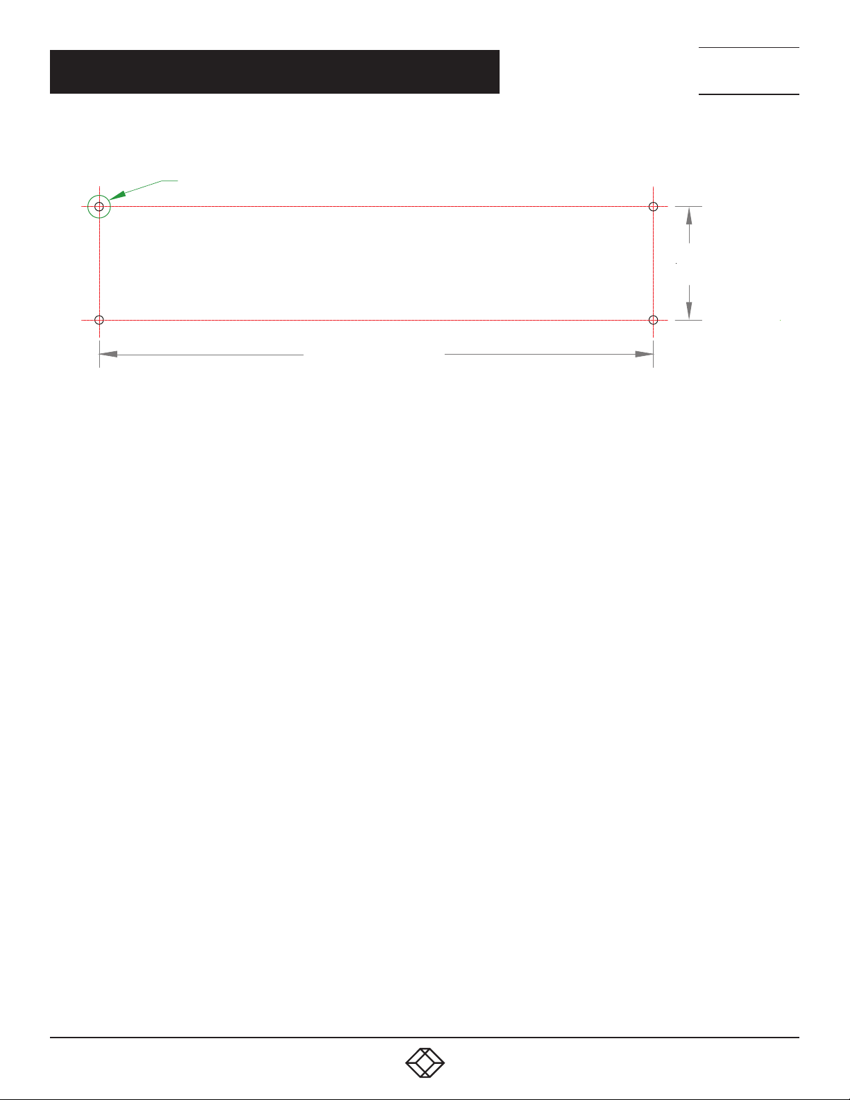
NOTE: The distance between the enclosure mounting holes is 42.0 mm x 205.5 mm.
1. Mark the center point of each of the four holes on your mounting surface by directly measuring.
2. Hardware recommendation: M3 locking washers and M3 screws (4 of each per extender), noting screw length will depend upon
thickness of mounting surface.
3. Drill through each of the four-hole markings on the mounting surface using a 3.97-mm (5/32”) drill bit.
4. Align the bottom enclosure holes to the newly drilled-out holes on the mounting surface.
5. Place a locking washer on each of the four screws and using a screwdriver, and fasten the extender into place.
NOTE: Do not exceed a screw depth of 10-mm (0.4”) into the unit or damage may occur.
18
1. 8 77. 8 77. 2 26 9 BLACKBOX.COM
Page 19
CHAPTER 4: MOUNTING OPTIONS
4.0mm (5/32”) in 4 places
205.5mm (8.0905”)
FIGURE 4-3. DIRECT SURFACE MOUNTING MEASUREMENT STENCIL
NEED HELP?
LEAV E TH E TEC H TO US
LIVE 24/7
TECHNICAL
SUPPORT
1. 8 7 7. 877.226 9
42.0mm
(3.0315”)
1. 8 77. 8 77. 2 26 9 BLACKBOX.COM
19
Page 20
NEED HELP?
LEAV E TH E TEC H TO US
LIVE 24/7
CHAPTER 5: TROUBLESHOOTING
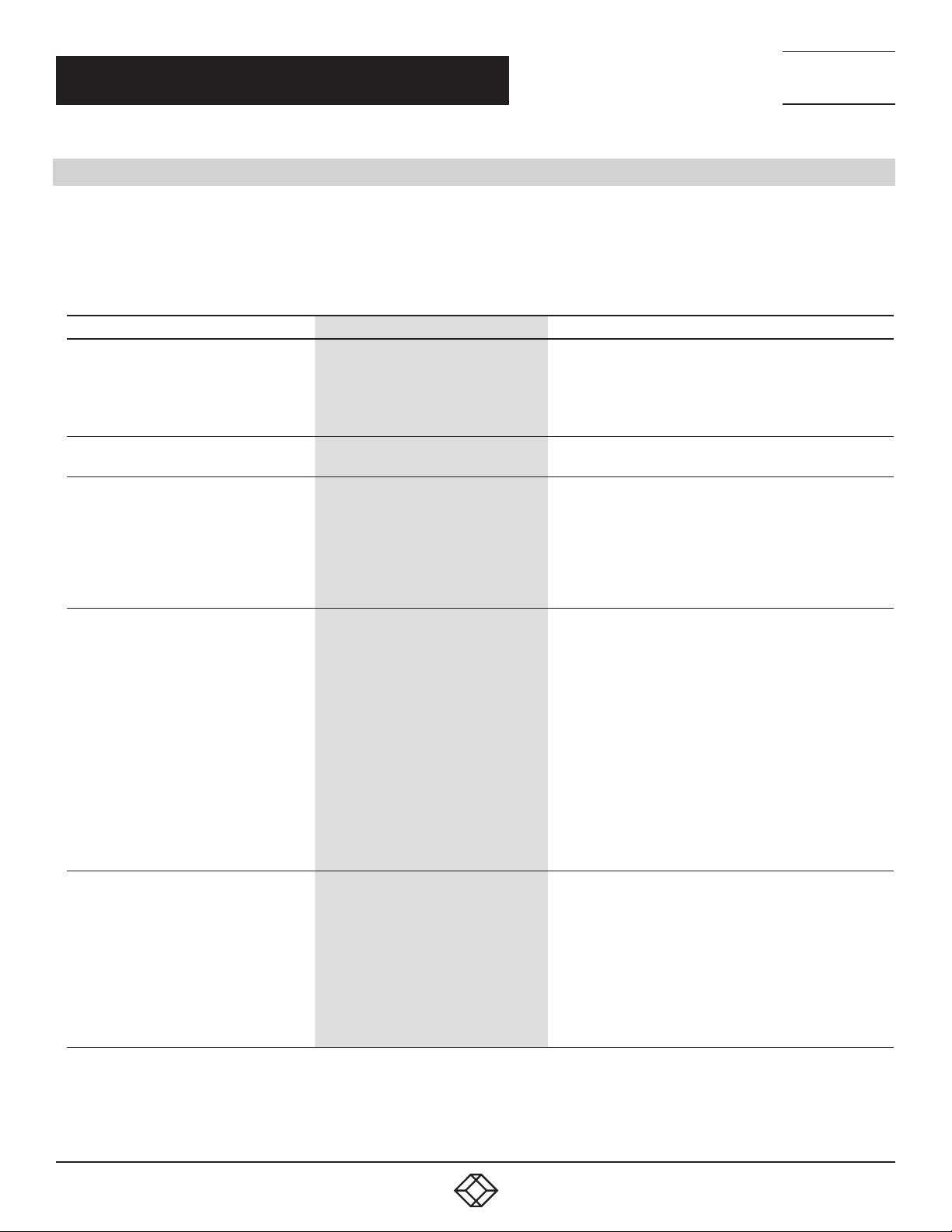
5.1 TROUBLESHOOTING TIPS
The following table provides troubleshooting tips. The topics are arranged in the order in which they should be executed in most
situations. If you are unable to resolve the problem after following these instructions, contact Black Box Technical Support
at 877-877-2269 or [email protected] for further assistance.
TABLE 5-1. TROUBLESHOOTING TIPS
PROBLEM CAUSE SOLUTION
1. Ensure that the AC power adapter is properly connected to
ALL LEDs are OFF on the Local and/or
Remote Extender.
POWER LED is ON, STATUS LED is OFF.
The Link LEDs on the Local and Remote
Extenders are OFF.
The LINK LEDs on the Local and Remote
Extenders are SOLID ON, but the USB 2
and USB 3 LEDs are OFF.
The USB 2 LED is SOLID ON, but the USB 3
LED is OFF.
The Local Extender and/or Remote
Extender is not receiving power
from the AC power adapter.
The unit has malfunctioned and requires
re-programming.
There is no connection between the
Local and Remote Extenders.
1. The host computer is not powered on.
2. The Local Extender is not connected
to a computer.
3. The host computer does not support
USB Hubs.
4. The unit is malfunctioning.
1. The Local Extender is not connected
to a USB 3 port.
2. The Local Extender is connected to
the host using a USB 2 cable.
3. The USB 3 cable connecting the
Local Extender to the host computer
is defective.
4. The host computer’s USB 3 controller
has malfunctioned.
the Local Extender and/or Remote Extender.
2. Check that the AC adapter is connected to a live source of
AC power. Check that the Local and/or Remote Extender’s
Power LED is illuminated.
Contact Black BoxTechnical Support at 877-877-2269
or [email protected] for assistance.
1. Ensure that a crossover OM3 multimode fiber optic cable
of no more than 656 feet (200 m) is connected between the
Local and Remote Extenders.
2. Connect a short fiber optic patch cable between the Local
and Remote Extenders. Recheck the link status. If the LINK
LED is now SOLID ON, the previous cable is defective or not
capable of supporting the link.
1. Disconnect all USB devices from the Remote Extender.
2. Disconnect the Local Extender from the host computer.
3. Disconnect the AC adapters from the Local and Remote
Extenders.
4. Reconnect the Local Extender to the host computer.
5. Reconnect the AC adapters to the Local and Remote
Extenders.
6. Check that the Local and Remote Extenders have
enumerated as USB hubs in Windows Device Manager,
macOS System Profiler or using “Isusb” command in a
Linux Terminal.
7. Contact Black Box Technical Support at 877-877-2269
or [email protected] for assistance.
1. Ensure that the Local Extender is connected to a USB 3
port on the host computer.
2. Ensure that the included USB 3.1 Gen 1 cable is being used
between the host computer and Local Extender.
3. Cold boot the host computer.
4. Replace the USB 3.1 Gen 1 cable with a different cable.
5. Contact Black BoxTechnical Support at 877-877-2269
or [email protected] for assistance.
TECHNICAL
SUPPORT
1. 8 7 7. 877.226 9
20
1. 8 77. 8 77. 2 26 9 BLACKBOX.COM
Page 21
CHAPTER 5: TROUBLESHOOTING
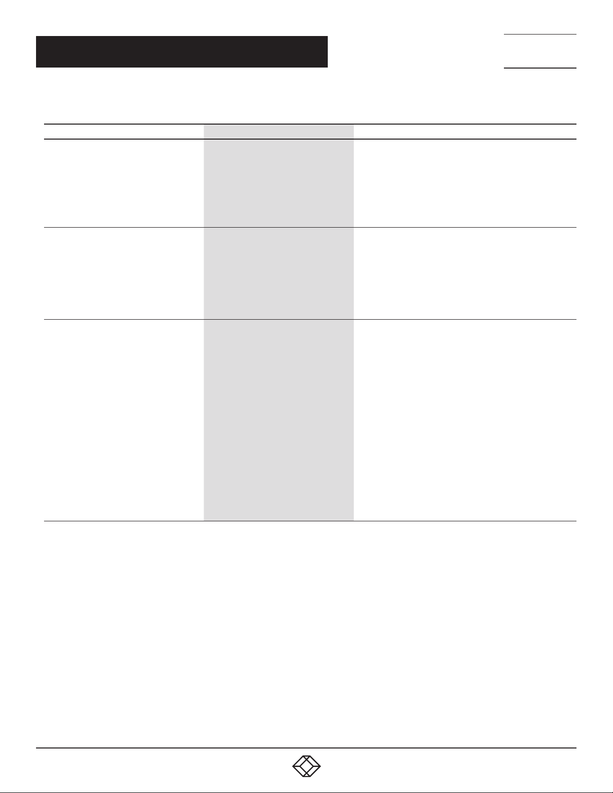
TABLE 5-1 (CONTINUED). TROUBLESHOOTING TIPS
PROBLEM CAUSE SOLUTION
The USB 3 LED is SOLID ON, but the USB 2
LED is OFF.
Both Local and Remote Extenders are
working, but the USB 2 or USB 3 LEDs
on the Local and Remote Extenders are
blinking.
ALL LEDs on both Local and Remote
Extenders are SOLID ON, but the USB
device is not operating correctly, or is
detected as an “Unknown Device” in the
operating system.
1. The USB cable connecting the Local
Extender to the host computer is
defective.
2. The host computer’s USB 2.0
controller has malfunctioned.
3. The host computer does not support
USB 2.
The Local and/or Remote Extender is in
suspend mode. For a variety of reasons,
the host computer may place the Local/
Remote Extender into suspend mode.
Typically, it is because there are no USB
devices attached, the USB device is
asleep, or the host computer is in a sleep
state or hibernating.
1. The USB device is malfunctioning.
2. The computer does not recognize the
USB device.
3. The application software for the USB
device is not operating.
4. The USB extender is malfunctioning.
1. Ensure that the included USB 3.1 Gen 1 cable is being used
between the host computer and Local Extender.
2. Cold boot the host computer.
3. Replace the USB 3.1 Gen 1 cable with a different cable.
4. Contact Black BoxTechnical Support at 877-877-2269 or
[email protected] for assistance.
1. Recover/resume the operating system from sleep or
hibernate modes (refer to your operating system’s
documentation).
2. Connect a USB device to the Remote Extender.
3. Use the connected device.
4. Contact Black BoxTechnical Support at 877-877-2269
or [email protected] for assistance.
1. Disconnect the extender from the computer.
2. Connect the USB device directly to the host computer.
3. If the device does not operate as expected, consult the
user documentation for the device.
4. Update the host computer BIOS, chipset or USB controller
drivers from the manufacturer’s website.
5. If the device operates as expected when directly connected
to the computer, connect another device to the extender and
reconnect it to the host computer.
6. If the second device does not operate, the extender may
be malfunctioning. Contact Black BoxTechnical Support at
877-877-2269 or [email protected] for assistance.
7. If the second device operates as expected, then the first
device may not be compatible with this extender. Contact
Black BoxTechnical Support at 877-877-2269
or [email protected] for assistance.
NEED HELP?
LEAV E TH E TEC H TO US
LIVE 24/7
TECHNICAL
SUPPORT
1. 8 7 7. 877.226 9
1. 8 77. 8 77. 2 26 9 BLACKBOX.COM
21
Page 22
CHAPTER 5: TROUBLESHOOTING
TABLE 5-1 (CONTINUED). TROUBLESHOOTING TIPS
PROBLEM CAUSE SOLUTION
1. Disconnect the extender from the computer.
2. Connect the USB 3 device directly to the host computer.
3. If the device does not operate as expected as a USB 3
device, consult the user documentation for that device or
try a different USB port on the host computer.
4. Update the host computer BIOS, chipset or USB controller
drivers from the manufacturer’s website.
5. If the device operates as USB 3 device when directly
connected to the computer, connect another USB 3 device
to the extender and reconnect it to the host computer.
6. If the second device does not operate as a USB 3 device,
the extender may be malfunctioning. Contact Black Box
Technical Support at 877-877-2269 or [email protected]
for assistance.
7. If the second device operates as a USB 3 device as expected,
the first device may not be compatible with this extender.
Contact Black Box Technical Support at 877-877-2269 or
[email protected] for assistance.
1. Check ambient temperature. Ensure temperature does not
exceed 122° F (50° C).
2. Power cycle the unit to remove LED status.
1. Remove external sources of heat or change location
of the unit.
2. Power cycle the unit to return to operation.
A USB 3 device is not enumerating as USB
3, or the operating system is notifying the
user that the device can “Perform Faster if
connected to a USB 3 port”.
All LEDs are flashing and the system is
operational.
All LEDs are flashing and the system
is NOT operational.
LEDs are scrolling LEFT to RIGHT, starting
wi th STATUS .
1. The USB device is malfunctioning.
2. The computer does not recognize the
USB device.
3. The application software for the USB
device is not operating.
4. The USB 3 port on the computer is
malfunctioning.
5. The USB extender is malfunctioning.
Unit is or was operating at an unsafe
temperature.
Unit has exceeded a safe operating
temperature.
Unit is programming. Wait for the unit to finish programming.
NEED HELP?
LEAV E TH E TEC H TO US
LIVE 24/7
TECHNICAL
SUPPORT
1. 8 7 7. 877.226 9
22
1. 8 77. 8 77. 2 26 9 BLACKBOX.COM
Page 23

CHAPTER 5: TROUBLESHOOTING
5.2 CONTACTING TECHNICAL SUPPORT
If you are experiencing problems not referenced in the Troubleshooting Guide, contact Black Box Technical Support
at 877-877-2269 or [email protected] for assistance and provide them with the following information:
Host computer make and mode
Type of operating system installed (e.g. Windows 10, macOS 10.12, etc.)
Part number and serial number of both the Local Extender and Remote Extender unit
Make and model of any USB device(s) attached to the product
Description of the installation
Description of the problem
NEED HELP?
LEAV E TH E TEC H TO US
LIVE 24/7
TECHNICAL
SUPPORT
1. 8 7 7. 877.226 9
1. 8 77. 8 77. 2 26 9 BLACKBOX.COM
23
Page 24

NEED HELP?
LEAV E TH E TEC H TO US
LIVE 24/7
APPENDIX A: REGULATORY INFORMATION
A.1 FCC RADIO FREQUENCY INTERFERENCE STATEMENT WARNING
This device complies with Part 15 of the FCC rules. Operation is subject to the following two conditions: (1) this device may not cause
harmful interference, and (2) this device must accept any interference received including interference that may cause undesired
operation.
This Class B digital apparatus complies with Canadian ICES-003 Issue 6.
A.2 CE STATEMENT
We, Black Box Corporation, declare under our sole responsibility that the USB 2.0 ICU544A, to which this declaration relates, is in
conformity with European Standard EN 55024, EN55032 and EN 61000, and RoHS Directive 2011/65/EU + 2015/863/EU.
A.3 IC STATEMENT
This Class A digital apparatus complies with Canadian ICES-003 Issue 6.
TECHNICAL
SUPPORT
1. 8 7 7. 877.226 9
A.4 WEEE STATEMENT
The European Union has established regulations for the collection and recycling of all waste electrical and electronic equipment (WEEE).
Implementation of WEEE regulations may vary slightly by individual EU member states. Check with your local and state government
guidelines for safe disposal and recycling or contact your national WEEE recycling agency for more information.
24
1. 8 77. 8 77. 2 26 9 BLACKBOX.COM
Page 25
NEED HELP?
LEAV E TH E TEC H TO US
LIVE 24/7
APPENDIX B: TECHNICAL GLOSSARY
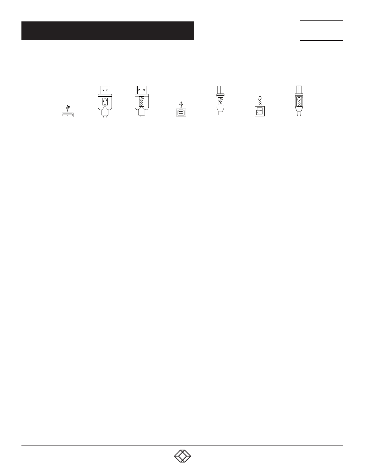
USB 3 and USB 2.0 Cables: USB cables have two distinct full-sized connectors. The Type A connector is used to connect the cable
from a USB device to the Type A port on a computer or hub. The Type B connector is used to attach the USB cable to a USB device.
TECHNICAL
SUPPORT
1. 8 7 7. 877.226 9
USB Type A
connector
USB 3 Type A
USB Type A port
connector
USB Type B port
USB Type B
connector
USB 3 Type B port
USB 3 Type B
connector
FIGURE B-1. USB TYPE A AND TYPE B CABLE CONNECTORS
Duplex LC: When a crossover fiber-optic cable is called for, the cable has the transmit signal on one end connected to the receive
signal at the other end.
1. 8 77. 8 77. 2 26 9 BLACKBOX.COM
25
Page 26

NEED HELP?
LEAV E TH E TEC H TO US
LIVE 24/7
APPENDIX C: DISCLAIMER/TRADEMARKS
TECHNICAL
SUPPORT
1. 8 7 7. 877.226 9
C.1 DISCLAIMER
Black Box Corporation shall not be liable for damages of any kind, including, but not limited to, punitive, consequential or cost of cover
damages, resulting from any errors in the product information or specifications set forth in this document and Black Box Corporation
may revise this document at any time without notice.
C.2 TRADEMARKS USED IN THIS MANUAL
Black Box and the Black Box logo type and mark are registered trademarks of Black Box Corporation.
Any other trademarks mentioned in this manual are acknowledged to be the property of the trademark owners.
26
1. 8 77. 8 77. 2 26 9 BLACKBOX.COM
Page 27

NOTES
NEED HELP?
LEAV E TH E TEC H TO US
LIVE 24/7
TECHNICAL
SUPPORT
1. 8 7 7. 877.226 9
1. 8 77. 8 77. 2 26 9 BLACKBOX.COM
27
Page 28

NEED HELP?
LEAVE THE TECH TO US
LIVE 24/7
TECHNICAL
SUPPORT
1.87 7. 8 7 7. 226 9
© COPYRIGHT 2020. BLACK BOX CORPORATION. ALL RIGHTS RESERVED.
ICU544A_USER_REV1.PDF
 Loading...