

QUICK START GUIDE
ICD400A
ISOLATED
RS-232 TO
RS-422/485
CONVERTER
24/7 TECHN IC AL S UPP ORT AT 877.877.2269 OR VISIT B LA CK BOX.COM
STEP 1 - Specifications
• Complies wi th FCC Class B and CE requirem ents.
• Withs tands temperature variations from -40 to +80
°C (-40 to +176 °F)
STEP 2 - What’s Included
Your package should include the following items. If
anything is missing or dama ged, conta ct Black Box
Technical Support at 877- 877-2269 or visit:
info@blackbox.com.
• RS-2 32 to RS -422/485 C onverter
• This Qu ick Start Guide
• 10-to 30-V DC power connector
USER-SUPPLIED COMPONENTS
• DIN rail clip (D RCLIP), optional
STEP 3 - Controls and Indicators
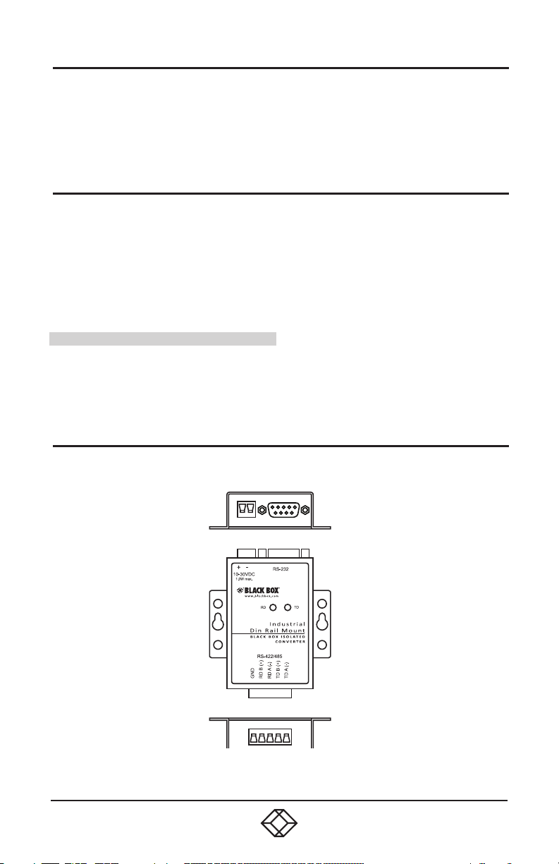
Figur e 3-1 shows the iso lated R S-232 to RS -422/485
converter. Table 3 -1 descr ibes its components.
1
Figure 3.1 Model ICD400A
2
3
4
5

TABLE 3-1. CONVERTER COMPONENTS
ID in Fig. 3-1 Component Description
1 Power connector
2 DB9 female connector RS-232 (wired as DCE)
3 Data LEDs
4 Mounting ears Used for panel mounting
5 R2-422/485 connector 5-position, removable
*6 8-position DIP switch Located on back of unit
*Se e Figure 3-2 .
Figure 3.2 DIP switch (located on back of unit).
NOTE : Shaded bla ck means the DIP switc h is ON.
2-position, removable
Green: ON when power is applied
Blinking: Data is flowing
STEP 4 - Pinouts and Terminal Identification
Figur e 4-1 and Table 4-1 describ e the RS -232
connector pinout.
TABLE 4-1. DB9 DCE FEMALE CONNECTOR PINOUT
Pin Signal Direction Pin Signal Direction
1 DCD
2 RD Output 7 RTS —
3 TD Input 8 CTS —
4 DTR — 9 RI —
5 GND — — — —
NOTE: PIns 1, 6, and 4 are tied together internally. Pins 7 and 8 are tied together internally.
Figure 4-1. DB9 connector pinout.
—
6 DSR —

Figur e 4-2 and Table 4-2 show the terminal
identification.
V(-)
Power supply
10–30 VDC, 2.5 W
A B C D E
Figure 4.2 Terminal Identification
TABLE 4-2. TERMINAL IDENTIFICATION
RS-422/485 4-Wire RS-485 2-Wire
A Ground A
B RDB(+) B Data B(+)
C RDA(-) C Data A(-)
D TDB(+) D —
E TDB(-) E —
Ground
V(+)
STEP 5 - Power Connection
Connect your exte rnal power sup ply to the 2-position
power te rminal bloc k A. The polarity is indic ated on the
front label. The converter will accept 10 to 30 VDC, 1.0
W maxim um. Th e terminal block will acce pt 28 to 12
AWG wire.

STEP 6 - Wiring Examples
In Figu re 6-1, the converter is set up to u se the in ternal
bias and n o termination.
Figure 6.1 RS-485 2-wire example.
In Figu re 6-2, the conver ter is set up to use internal
bias and n o termination with four wires.
NOTE: Shaded black means the DIP switch is ON.
RS-485 4-wire DIP switch.*
* NOTE: Shaded black means the DIP switch is ON.
Figure 6-2. RS-485 4-wire example.
RS-422 4-wire DIP switch.*

STEP 7 - Bias and Termination
The circuit c an be biased using the b uilt-in 2k O hm
pull-up and pull -down resistors. This is c ontrolled w ith
DIP switch position 5. The de fault setting is ON ( bias
resi stors in).
When an RS- 485 networ k is in an idle state, all no des
are in lis ten (receive) mode. Under this condition , there
are no ac tive drivers o n the network. All d rivers are
tri-stated. Without anything driving the network, the
state of the line i s unkn own. If the volt age level at the
recei ver’s A and B inp uts is less than ±200 mV, the logic
level at the output of th e receivers w ill be th e value of
the last bit rec eived. To maintai n the proper id le volt age
state, bias resistors must be applied to force the data
lines to the idle c ondition.
If termination is nec essary on th e receive lines, a
built-in 120 Oh m resis tor can be switched in using DI P
switch position 6. In m ost cases, te rmination is not
required. The default setting is OFF (te rmination ou t).
Termination is used to matc h impedance of a node to
the impedance of the transmission line being used.
Termination inc reases load on the drivers, requir es
installation complexity, changes biasing requirements,
and makes system modif ication more difficult.
Generally, te rmination sh ould only be used for long
distances. “If in doubt, leave it o ut.”
STEP 8 - Loopback Test
• Configure for RS-485 4-wire.
• Jumper term inals B to D and C to E.
• Connect a PC to the RS -232 port.
• TD and RD LEDs are ON whe n power is applied.
• Using hyperter minal o r a similar program, connect
to the app ropriate COM port. Turn off hy pertermi nal
local echo.
• Transmi t data. The same data should b e returned.
When data is sent and looped back, the TD and RD
LEDs bl ink on and off in dicating data flow.


COPYRIGHT 2018 BLACK BOX CORPORATION. ALL RIGHTS RESERVED.
Documentation Number: pn710-00009-00_r2_ICD400A_2518qsg
 Loading...