

DECEMBER 2001
IC951A IC960A
IC952A IC961A
IC953A IC963A
IC954A-M IC964A
Mini Interface Converters
CUSTOMER SUPPORT INFORMATION
Order toll-free in the U.S.: Call 877-877-BBOX (outside U.S. call 724-746-5500)
FREE technical support 24 hours a day, 7 days a week: Call 724-746-5500 or fax 724-746-0746
Mailing address: Black Box Corporation, 1000 Park Drive, Lawrence, PA 15055-1018
Web site: www.blackbox.com • E-mail: info@blackbox.com

1
MINI INTERFACE CONVERTERS
Contents
Chapter Page
1. Specifications................................................... 3
2. Introduction.................................................... 5
2.1 Description ............................................... 5
2.2 Available Models....................................... 6
2.3 Features................................................... 10
3. Application .................................................... 11
4. Schematic Diagrams ..................................... 12

2
MINI INTERFACE CONVERTERS
TRADEMARKS USED
IN THIS MANUAL
Any trademarks mentioned in this manual are
acknowledged to be the property of the trademark owners.

3
MINI INTERFACE CONVERTERS
Data Rates — Up to 200 kbps for all
models with a V.24/RS-232
interface; Up to 2048 kbps
for all other models
Transmission
Format — IC952A, IC953A:
Asynchronous; All other
models: Synchronous,
transparent to protocol
Operating
Temperature — 32 to 122°F (0 to 50°C)
Relative Humidity
Tolerance — 10 to 90%, noncondensing
Power — IC951A: Requires
connection to an external
power supply providing
9 VDC @ 300 mA (part
numbers PS017 and
PS017E); All other models:
No AC power required
1. Specifications

4
MINI INTERFACE CONVERTERS
Size — 0.9"H x 2.1"W x 4.3"D (2.3 x
5.3 x 10.9 cm); All models
also include a built-in
6.5-foot (2-m) cable
Weight — 14 oz. (397 g), including
cable and connector
Connectors — See the chart below
Model Connector 1 (DTE) Connector 2 (DCE)
IC951A 15-pin female 37-pin male
IC952A 25-pin female Terminal block
IC953A Terminal block 25-pin male
IC954A-M 25-pin male 37-pin male
IC960A 34-pin male 37-pin male
IC961A 34-pin male 25-pin male
IC963A 37-pin female 15-pin male
IC964A 25-pin female 34-pin male

5
MINI INTERFACE CONVERTERS
2.1 Description
These interface converters enable connection
between DTE and DCE data-communications
equipment with different interfaces. They operate
in synchronous applications (except for the
IC952A and IC953A, which operate in
asynchronous applications) at data rates up to
2048 kbps with balanced interface at both ends,
or at data rates up to 200 kbps with V.24/RS-232
at one end.
Mini Interface Converters perform both the
physical and electrical conversion between the two
interfaces. The circuitry is designed to provide
short-range interface conversion.
Most models operate without AC power, using
ultra-low power from the DTE and DCE
equipment data and control signals.
2. Introduction

6
MINI INTERFACE CONVERTERS
2.2 Available Models
IC954A-M
For converting between V.24/RS-232 and
V.36/RS-422 interfaces. The IC954A-M is switchselectable and is used either for connecting a
V.24/RS-232 DTE to a V.36/RS-422 DCE, or for
connecting a V.24 DCE to a V.35 DTE.
Installing the Converter is simple, since it plugs
directly into the DCE and DTE. Connect the
Converter directly to the RS-232/V.24 device, and
the cable connector to the RS-449 device. The
Converter comes factory strapped for RS-232
DTE/RS-449 DCE. To alternate this configuration:
1) Separate the two halves of the plastic cover by
pressing the marked places on the sides,
starting at the cable end.
2) Remove the 40-pin DTE/DCE socket by gently
grasping both sides and slowly moving it from
side to side.
3) Replace the socket so that the DCE faces the
RS-232 connector and the DTE faces the RS-449
device. Make sure that the pins are aligned with
the socket.

7
MINI INTERFACE CONVERTERS
NOTE
The DCE/DTE arrows on the shunt indicate the device you
are connecting to, not what the converter interface is.
4) Close the unit by pressing the two plastic covers
together.
IC952A, IC953A
For converting between V.24/RS-232 and
V.11/RS-422 interfaces. These converters are
switch-selectable and are used for connecting a
V.24/RS-232 DTE to a V.11/RS-422 DCE, or a V.24
DCE to a V.11 DTE. These Converters convert only
the data signals, not the control signals, and are
suitable only for asynchronous applications.
To install the Converter:
1) Separate the two halves of the plastic cover by
pressing the marked places on the sides,
starting at the cable end.
2) Connect the V.11 two twisted pairs to the screw
terminal block; transmit pair to “XMT” and
receive pair to “RCV.” A ground is provided for
optional connection of the cable shield.
3) Set the DTE/DCE switch of the Converter to
the required position (factory set to DCE).

8
MINI INTERFACE CONVERTERS
4) Note that the Converter connects only the data
signals. Some of the V.24 control signals are
pre-set depending on the DTE/DCE switch.
5) To close the Converter, simply press the two
halves of the cover together.
6) Connect the Converter directly to the 25-pin
connector of the terminal or computer port,
and fasten with the two screws—one on each
side of the Converter.
IC951A
For converting between RS-449/422 (V.36/V.11)
and X.21 interfaces. The Converter is used for
connecting a V.36 DCE to an X.21 DTE, and has a
built-in buffer to accommodate phase differences
between the receive and transmit clocks of the
DCE. Once the connectors are plugged into the
DTE and DCE, connect the DC jack to the DC
socket on the side of the Converter and insert the
wall-mount transformer into the AC mains. Note
that an internal elastic buffer is provided to solve
clock phase problems. This Converter requires an
external power supply.

9
MINI INTERFACE CONVERTERS
IC964A, IC961A
For converting between RS-530 and V.35 interfaces.
The Converter is used for connecting an RS-530
DTE to a V.35 DCE, or an RS-530 DCE to a V.35
DTE. To install the Converter, simply plug it
directly into the DTE or DCE. No strapping
adjustments are required. Just connect the 25-pin
connector to the RS-530 device and the other
connector to the V.35 device, and it’s ready to
operate.
IC960A
The Converter is used for connecting a V.35 DTE
to a 422 (V.36) DCE. To install the Converter,
simply connect the Converter to the RS-422/V.36
device and the cable connector to the V.35 device.
IC963A
For converting between X.21 and RS-422. The
Converter is used to connect an X.21 DCE to an
RS-422 DTE.

10
MINI INTERFACE CONVERTERS
2.3 Features
•Conversion between V.24/RS-232, V.35, V.36,
RS-449/422, RS-530/422, and X.21 interfaces.
•Equipped with cable and connectors.
•Transparent to protocol.
•High speed, up to 2 Mbps (for most models).
•Immediate installation.
•No AC power required (for most models).
•Compact and lightweight.

11
MINI INTERFACE CONVERTERS
X and Y interfaces can be V.24 (RS-232), V.35, V.36
(RS-422), X.21, or RS-530.
3. Application
Synchronous modem
or multiplexor
Synchronous terminal
or multiplexor
Y interface
X interface
DCE
DTE

12
MINI INTERFACE CONVERTERS
4. Schematic Diagrams
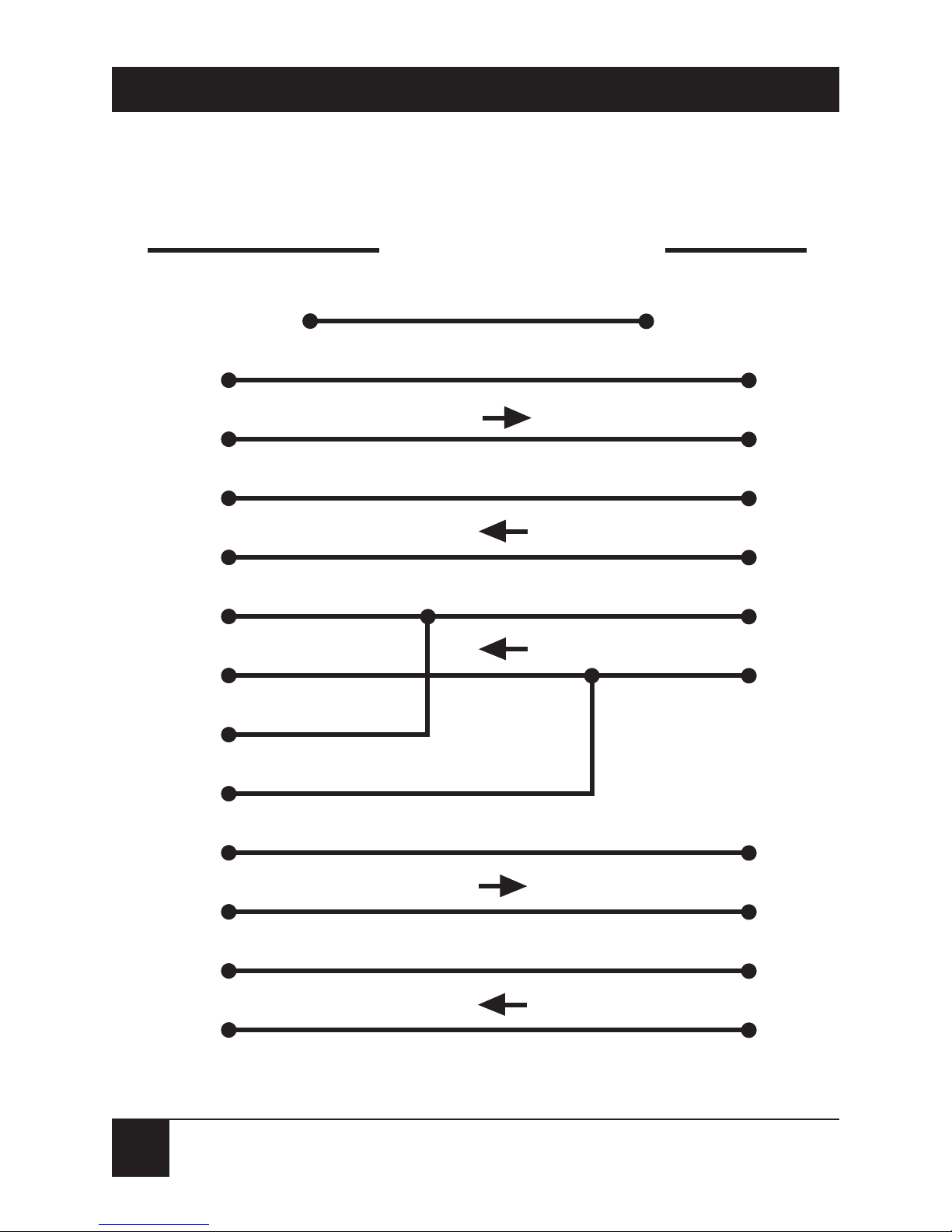
Figure 4-1. IC951A.
Ia
5
Ib
12
Ca
3
RSa
7
Cb
10
X.21 (DTE)
FEMALE
Signal
GND
V.36 (DCE)
MALE
1
1
Signal
GND
20, 37, 19
8
Protective
GND
Shield
Ra
4
Rb
Sa
Sb
13
+
-
11
6
* Wall-mount transformer should be 9V/300 mA DC.
RSb
25
13
31
+
-
RRa
RRb
Ta
2
RTb
26
SDa
4
22
SDb
+
-
+
-
8
RTa
+
-
RDb
24
6
RDa
Tb
9
CO CI
ELASTIC
BUFFER
DO DI
+
-
STa
STb
23
5

13
MINI INTERFACE CONVERTERS
Figure 4-2. IC952A and IC953A.
TD
V.24 (DTE) V.11 (DCE)
2
TX+
TX-
RD
3
RCV+
RCV-
TD
V.24 (DCE) V.11 (DTE)
2
RCV+
RCV-
RD
3
TX+
TX-
DTE PositionDCE Position
+V
RTS 4
CTS 5
DSR 6
DCD 8
DTR 20
+V
DCD 8
+V
DSR 6
+V
DTR 20
RTS 4
CTS 5

14
MINI INTERFACE CONVERTERS
Figure 4-3. IC954A-M.
CS-a
9
CTS
CS-b
27
DM-a
11
DSR
DM-b
29
TR-a
12
TR-b
30
RR-a
13
DCD
8
RR-b
31
5
6
RS-a
7
RTS
4
RS-b
25
V.36 (DTE)
Signal GND
V.24 (DCE)
1 1
Signal GND
7
19, 37, 20
Frame GND
Shield
R
R
R
DTR
20
R
R
ST-b
23
ST-a
5
RT-a
TC
RT-b
15
TT-a
TT-b
SD-a
SD-b
RD-a
RD-b
LL LL
18
RL RL
21
TM TM
25
17
TD
2
+
-
4
22
EXT-TC
24
+
-
35
RC
17
8
26
RD
3
6
24
10
14
18
NC
NC
NC
R = 100Ω

15
MINI INTERFACE CONVERTERS
Figure 4-4. IC954A-M.
CTS CS-a
CS-b
27
DSR DM-a
DM-b
29
DTR
20
TR-b
30
DCD
RR-a
13
RR-b
31
9
11
RTS RS-a
7
RS-b
25
V.24 (DTE)
Signal GND
V.36 (DCE)
1 1
Signal GND
20, 37, 19
Shield
Frame GND
R
R
R
TR-a
12
ST-b
23
ST-a
5
RT-a
TC
RT-b
15
TT-a
TT-b
SD-a
SD-b
RD-a
RD-b
LL LL
10
RL RL
14
TM TM
18
17
TD
2
22
EXT-TC
24
35
RC
17
8
26
RD
3
6
24
18
21
25
NC
NC
NC
R = 100Ω
R
R
+
-
+
-
4
+
-
7
5
8
4
6

16
MINI INTERFACE CONVERTERS
Figure 4-5. IC960A.
CTS
D
CS-a
9
CS-b
27
DSR
E
DM-a
11
DM-b
29
DTR TR-a
TR-b
DCD
F
RR-a
13
RR-b
31
TC-a
Y
ST-a
TC-b
AA
ST-b
RC-a
V
RT-a
RC-b
X
RT-b
26
TD-a
P
SD-a
4
TD-b
S
SD-b
22
RD-a
R
RD-a
6
RD-b
T
RD-b
24
EC-a
U
TT-a
17
EC-b
W
TT-b
35
Signal GND
B
RTS
37, 20, 19
RS-a
Signal GND
RS-b
C 7
25
H
12
30
5
23
8
V.35 (DTE) RS-449/V.36 (DCE)
RS-422/V.36 (DCE)
V.35 (DTE)

17
MINI INTERFACE CONVERTERS
Figure 4-6. IC961A.
CTS
D
CTS-a
5
CTS-b
13
DSR
E
DSR-a
6
DSR-b
22
DTR DTR-a
DTR-b
DCD
F
DCD-a
8
DCD-b
10
TC-a
Y
TC-a
TC-b
AA
TC-b
RC-a
V
RC-a
RC-b
X
RC-b
9
TD-a
P
TD-a
2
TD-b
S
TD-b
14
RD-a
R
RD-a
3
RD-b
T
RD-b
16
ETC-a
U
ETC-a
24
ETC-b
W
ETC-b
11
Signal GND
B
RTS
7
RTS-a
Signal GND
RTS-b
C 4
19
H
20
23
15
12
17
V.35 (DTE) RS-530 (DCE)
18
MINI INTERFACE CONVERTERS
Figure 4-7. IC963A.
RR-a
13
I-a
RR-b
31
I-b
ST-a
5
S-a
ST-b
23
S-b
13
RT-a
8
RT-b
26
SD-a
4
T-a
2
SD-b
22
T-b
9
RD-a
6
R-a
4
RD-b
24
R-b
11
5
12
6
RS-a
7
C-a
3
C-b
10
RS-b
25
RS-449/V.36 (DTE)
37, 20, 19
8
Signal GND
X.21 (DCE)
Signal GND

19
MINI INTERFACE CONVERTERS
Figure 4-8. IC964A.
CTS-a
5
CTS
D
DSR-a
6
DSR
E
DTR-a DTR
DCD-a
8
DCD
F
TC-a
15
TC-a
TC-b
12
TC-b
RC-a
17
RC-a
RC-b
9
RC-b
X
TD-a
2
TD-a
P
TD-b
14
TD-b
S
RD-a
3
RD-a
R
RD-b
16
RD-b
T
ETC-a
24
ETC-a
U
ETC-b
11
ETC-b
W
Signal GND
7
RTS-a
B
RTS
Signal GND
4 C
H
Y
AA
V
RS-530 (DTE) V.35 (DCE)
RTS-b
19
CTS-b
13
DSR-b
22
20
DTR-b
23
10
DCD-b

NOTES

1000 Park Drive • Lawrence, PA 15055-1018 • 724-746-5500 • Fax 724-746-0746
© Copyright 2001. Black Box Corporation. All rights reserved.
 Loading...