

Page 1
CUSTOMER
SUPPORT
INFORMATION
Call our Technical Support Specialists to discuss your application.
For 24-hour technical support: Call (412) 746-5500 or Fax: 1-800-321-0746
To order: Call (412) 746-5500 8:00 A.M. to 8:00 P.M. EST
Mail order: Black Box Corporation, P.O. Box 12800, Pittsburgh, PA 15241
JANUARY 1995
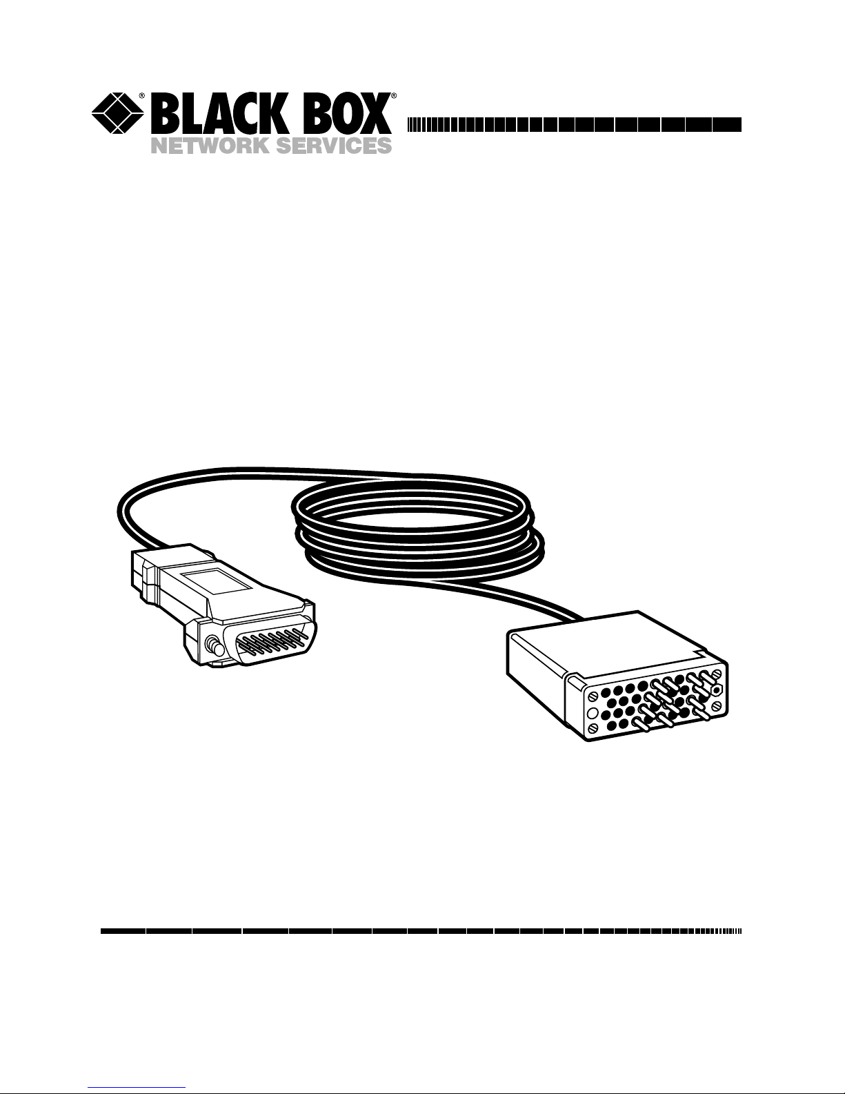
IC940A-F
IC940A-M
V.35/X.21 Bi-Directional
Interface Converter
Page 2
000
V.35/X.21 BI-DIRECTIONAL INTERFACE CONVERTER
2
Contents
Chapter Page
1. Specifications....................................................................................3
2. Introduction.....................................................................................4
3. Installation .......................................................................................5
Page 3
000
V.35/X.21 BI-DIRECTIONAL INTERFACE CONVERTER
3
1. Specifications
Cable length between connectors
—
6.5 ft. (1.9 m)
Power
—interface-powered V.35
pins C, D, E, or F or X.21 pins 3,
10, or 15
Size
—V.34 connector: 0.9"H x 2"W
x 2.5"D (2.3 x 5.1 x 6.4 cm),
DB15 connector: 1"H x 1.8"W x
2.8"D (2.5 x 4.6 x 7.1 cm)
Weight
—0.9 lb. (0.4 kg)
Data Rates
—Up to 2048 kbps
Transmission Format
—
Synchronous, transparent to
protocol
Transmission Mode
—Full-duplex
Temperature
—32° to 122° F
(0° to 50° C)
Humidity
—Up to 90%,
noncondensing
Interface Connections
—
V.35: IC940A-M M/34 male
(configured as DCE),
IC940A-F M/34 female
(configured as DCE);
X.21: IC940A-M, IC940A-F:
DB15 male (configured as DTE)
Page 4

000
V.35/X.21 BI-DIRECTIONAL INTERFACE CONVERTER
4
2. Introduction
The V.35/X.21 Bi-Directional
Interface Converter performs bi-
directional conversion of both the
physical and electrical specifications
of a V.35 device to those of an X.21
device.
Two models are available for
connecting a V.35 DTE to an X.21
DCE:
• IC940A-M: Male V.35 (DCE) to
Male DB15 (DTE)
• IC940A-F: Female V.35 (DCE)
to Male DB15 (DTE)
Page 5

000
V.35/X.21 BI-DIRECTIONAL INTERFACE CONVERTER
5
3. Installation
There are no internal jumpers or
switch setting to configure. The
converter is transparent to baud
rate and protocol and contains only
passive components.
A typical application appears in
Fig. 3-1
.
Choose a location so that you can
connect the devices directly to the
converter. The units are designed
to operate over short distances. We
do not recommend attaching
additional cables to the ends of the
converter.
Connect the M34/V.35 DCE
connector directly to the DTE
equipment. Connect the
DB15/X.21 connector directly to
the DCE equipment.
Fig. 3-1. Typical Application.
Bridge
V.35
M/34
X.21
DB15
X.21 Modem
Page 6

000
V.35/X.21 BI-DIRECTIONAL INTERFACE CONVERTER
6
Fig. 3-2. Pins Supported.
IC940A
V.35 DCE/X.21 DTE
Schematic Diagram
V.35 (DCE)
FEMALE/MALE
X.21 (DTE)
MALE
Signal GND Signal GNDB8
RTS C-aC3
C-b10
CTS D
DSR E
DCD 1-aF5
TC-a S-aY6
TC-b S-bAA 13
RC-a V
RC-b X
TD-a T-aP2
TD-b T-bS9
RD-a R-aR4
RD-b R-bT11
1-b12
Page 7

P.O. Box 12800 • Pittsburgh, PA 15241 • (412) 746-5500 • Fax (412) 746-0746
© Copyright 1995. Black Box Corporation. All rights reserved.
 Loading...