

FEBRUARY 1998
IC933A
IC944A
V.24/X.21 Interface Converter
X.21/V.24 Interface Converter
CUSTOMER SUPPORT INFORMATION
Order toll-free in the U.S. 24 hours, 7 A.M. Monday to midnight Friday: 877-877-BBOX
FREE technical support, 24 hours a day, 7 days a week: Call 724-746-5500 or fax 724-746-0746
Mail order: Black Box Corporation, 1000 Park Drive, Lawrence, PA 15055-1018
Web site: www.blackbox.com • E-mail: info@blackbox.com

2
V.24/X.21 AND X.21/V.24 INTERFACE CONVERTERS
1. Specifications
Speed — Up to 200 Kbps
Length — 6.5 feet (2 m)
Operation — Synchronous, full- or half-duplex
Interfaces — RS-232C/V.24, X.21
Connectors — IC933A: (1) DB25 (male) DTE,
(1) DB15 (male) DCE;
IC944A: (1) DB25 (male) DCE,
(1) DB15 (female) DTE
Power — 6.3 volts DC (35 mw) from pin 2,
4, or 20 of the RS-232 interface
Size — 0.9"H x 2.1"W x 4.3"D
(2.2 x 5.5 x 9 cm)
Weight — 0.8 lb. (0.4 kg)

3
V.24/X.21 AND X.21/V.24 INTERFACE CONVERTERS
2. Features
•Converts RS-232/V.24 to X.21 interface
and vice versa.
•Equipped with cable and connectors.
•Transparent to protocol.
•Installs immediately.
•Operates without AC power.
•Compact and lightweight.
•Bidirectional data transfer.

4
V.24/X.21 AND X.21/V.24 INTERFACE CONVERTERS
3. General
The V.24/X.21 Interface Converter Model IC933A
connects and converts from V.24 DTE to X.21
DCE. Model IC944A connects and converts from
X.21 DTE to V.24 DCE. Users can take advantage
of high-speed trunk lines with X.21 interfaces and
still use existing V.24 multiplexers, modems, and
terminals. The compact, lightweight conversion
unit provides complete electrical and mechanical
conversion. It operates without mains power supply
by using ultra low power from the standard
RS-232C/V.24 data and control signal voltages.

5
V.24/X.21 AND X.21/V.24 INTERFACE CONVERTERS
4. Applications
Model IC933A installs between a V.24 terminal
or multiplexor and an X.21 modem and Model
IC944A installs between an X.21 terminal or
multiplexor and a V.24 modem. Figures 4-1
and 4-2 illustrate these applications.
Figure 4-1. Typical Application of the IC933A.
Figure 4-2. Typical Application of the IC944A.
X.21
MODEM
TERMINAL OR
MUX
IC933A
V.24/X.21
V.24
X.21
MODEM
TERMINAL OR
MUX
IC944A
X.21/V.24
V.24

6
V.24/X.21 AND X.21/V.24 INTERFACE CONVERTERS
5. Installation
5.1 Installing the V.24 DTE/X.21 DCE (IC933A) Model
To install the unit, simply plug its DB25 (male)
connector directly into the DB25 (female)
connector on the RS-232/V.24 device (DTE).
Attach the unit’s DB15 (male) connector to the
DB15 (female) connector on the X.21 device
(DCE).*
5.2 Installing the X.21 DTE/V.24 DCE (IC944A) Model
To install the unit, simply plug its DB15 (female)
connector into the DB15 (male) connector on the
X.21 device (DTE). Attach the unit’s DB25 (male)
connector to the DB25 (female) connector on the
V.24 device (DCE).*
*NOTE
If you need to change the gender of the unit’s connectors,
use gender changers or short cables. Do not use extreme
lengths of cable. Since the unit operates at low power,
using cables that are too long will affect the unit’s operation.

7
V.24/X.21 AND X.21/V.24 INTERFACE CONVERTERS
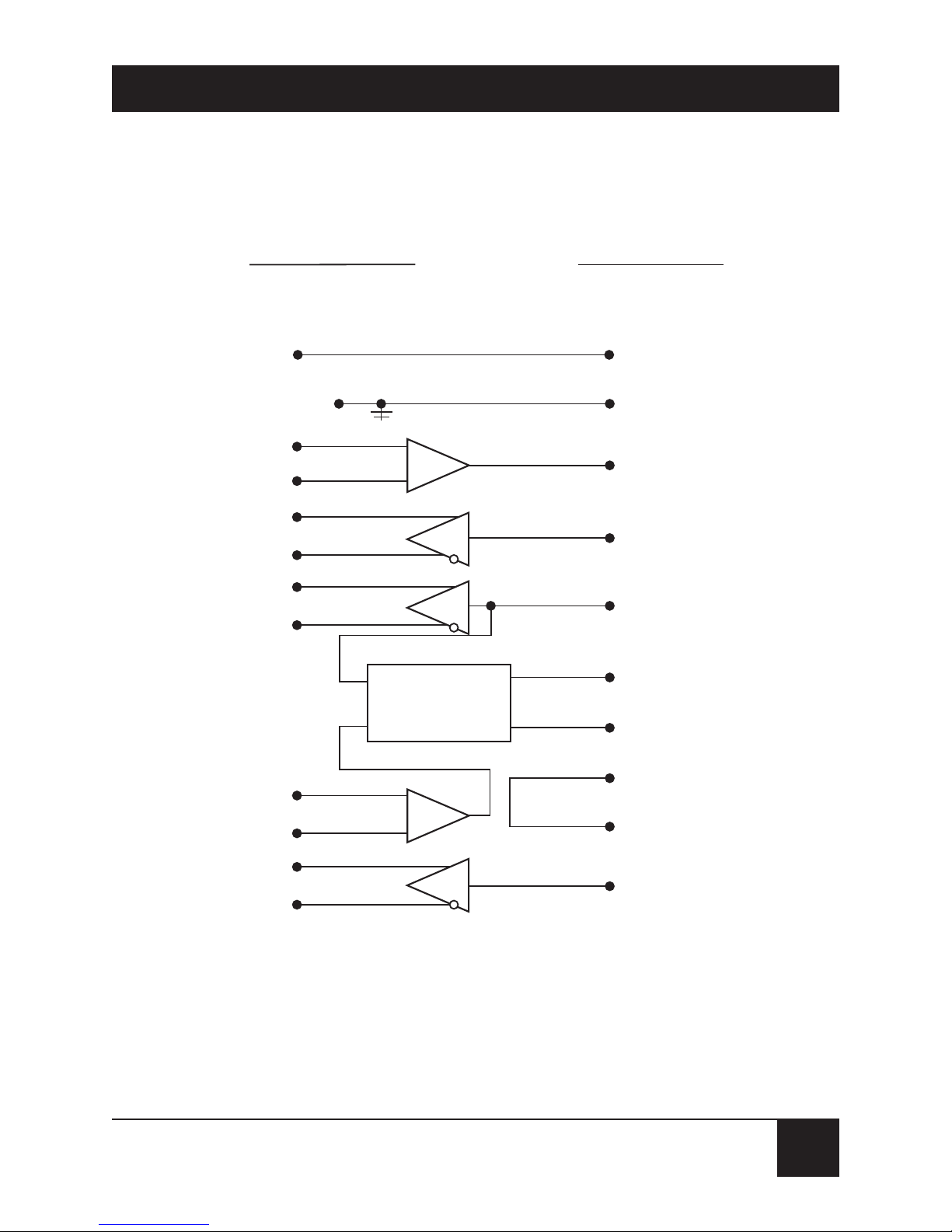
6. Pinning Diagrams
Figures 6-1 and 6-2 show the pinning of each unit.

8
V.24/X.21 AND X.21/V.24 INTERFACE CONVERTERS
Figure 6-1. IC933A Pinning.
RTS
4
10
3
C-b
C-a
CTS
V.24 DTE/X.21 DCE
Schematic Diagram
V.24 (DTE) X.21 (DCE)
DB25 (Male) DB15 (Male)
DCD
TC
RC
TD
RD
8
15
17
2
3
12
5
13
6
9
2
11
4
I-b
I-a
S-b
S-a
T-b
T-a
R-b
R-a
+
-
+
-
+
-
DSR
DTR
Signal GND
Protective
GND
Shield
20
7
9
V.24/X.21 AND X.21/V.24 INTERFACE CONVERTERS
Figure 6-2. IC944A Pinning.
I-b
I-a
C-b
C-a
S-b
S-a
T-b
T-a
R-b
R-a
Shield
Signal GND
RTS
DCD
TC
RC
TD
RD
4
8
15
17
2
3
6
9
2
11
4
X.21 DTE/V.24 DCE
Schematic Diagram
Protective GND
1
Signal GND
7
DSR
DTR
20
Ck In
Data In
Ck In
Data Out
Elastic
Buffer
+
-
+
-
V.24 (DCE)
DB25 (Male)
X.21 (DTE)
DB15 (Female)
12
5
10
3
13
1
8
6
 Loading...