

Page 1
USER MANUAL
IC830A , IC831A
USB 2.0 TO
RS-485
CONVERTER
24/7 TECHNICAL SUPPORT AT 1.877.877.2269 OR VISIT BLACKBOX.COM
USB to RS-485 4 wire
Model IC831A
Page 2

NEED HELP?
LEAV E TH E TEC H TO US
LIVE 24/7
TABLE OF CONTENTS
TECHNICAL
SUPPORT
1. 8 7 7. 8 7 7. 2 2 69
1. SPECIFICATIONS ........................................................................................................................................................................... 3
1.1 General Specifications ............................................................................................................................................................................. 3
1.2 Dimensional Diagrams ............................................................................................................................................................................. 4
2. OVERVIE W ...................................................................................................................................................................................... 5
2.1 Introduction ...............................................................................................................................................................................................5
2.2 Features .................................................................................................................................................................................................... 5
2.3 What’s Included ........................................................................................................................................................................................5
2.4 Hardware Description ..............................................................................................................................................................................6
3. I NSTALLATION .............................................................................................................................................................................. 7
3.1 STEP 1: Install the Drivers ........................................................................................................................................................................ 7
3.2 STEP 2: Connect the Converter .............................................................................................................................................................. 7
3.2.1 IC830A (2-Wire Model) Wiring ......................................................................................................................................................................... 7
3.2.2 IC831A (4-Wire Model) Wiring .........................................................................................................................................................................7
3.3 STEP 3: Loopback Test (4-Wire Model Only) ......................................................................................................................................... 8
3.4 STEP 4: Back-to-Back Test (2-Wire Model Only) ................................................................................................................................... 9
3.5 Pinouts ......................................................................................................................................................................................................9
4. OPERATION .................................................................................................................................................................................. 10
5. TROUBLESHOOTING ................................................................................................................................................................... 11
APPENDIX A. REGULATORY INFORMATION ................................................................................................................................ 12
A.1 FCC Statement ....................................................................................................................................................................................... 12
A.2 CE Declaration of Conformity ............................................................................................................................................................... 12
A.3 NOM Statement ..................................................................................................................................................................................... 13
APPENDIX B. DISCLAIMER/TRADEMARKS ................................................................................................................................. 14
B.1 Disclaimer ............................................................................................................................................................................................... 14
B.2 Trademarks Used in this Manual ............................................................................................................ ..............................................14
2
1. 8 7 7. 8 7 7. 2 26 9 BLACKBOX.COM
Page 3

CHAPTER 1: SPECIFICATIONS
1.1 GENERAL SPECIFICATIONS
TABLE 1-1. SPECIFICATIONS
SPECIFICATION DESCRIPTION
Serial Technology
RS-485 2-Wire Data A (-), Data B (+), Ground
RS-485 4-Wire
Connector DB9 female
Data Rate Up to 921.6 kbps
USB Technology
Connector USB Type B female
Standard 2.0 (backward-compatible)
Data Rate 12 Mbps
Power
Source USB port
Input Voltage 5 VDC
Consumption 0.5 W (low-power device, draws less than 100 mA)
Software
Driver CD Windows
Mechanical
Dimensions 0.6"H x 2.3" W x 1.3"D (1.6 x 5.8 x 3.2 cm)
Weight 0.23 lb. (0.10 kg) with USB cable
Enclosure In-line mounted, plastic
Environmental
Operating Temperature 32 to 158° F (0 to 70° C)
Storage Temperature -40 to +185° F (-40 to +85° C)
Operating Humidity 0 to 95%, relative humidity, noncondensing
MTBF
MTBF Method Parts count reliability prediction
Approvals
Compliance FCC, CE
EU
EMC
TDA (-), TDB (+), RDA (-), RDB (+), GROUND
IC830A (2-wire model): 2130833 hours
IC831A (4-wire model): 1869313 hours
2014/30/EU: Electromagnetic Compatibility Directive
2011/65/EU: Reduction of Hazardous Substances Directive
EN 55022:2010 + AC: Information Technology Equipment - Radio Disturbance Characteristics - Limits and
Methods of Measurement
EN 61000-6-1: Generic Immunity Standard for Residential, Commercial, and Light Industrial Environments
EN 61000-4-2: Electrostatic Discharge (ESD) Immunity
EN 61000-4-3: Radiated Field Immunity (RFI)
EN 61000 -4-4: Electrical Fast Transients (EFT) Burst Immunity
EN 61000-4-5: Surge Immunity
EN 61000-4-6: RF Conducted Immunity
NEED HELP?
LEAV E TH E TEC H TO US
LIVE 24/7
TECHNICAL
SUPPORT
1. 8 7 7. 8 7 7. 2 2 69
1. 8 7 7. 8 7 7. 2 26 9 BLACKBOX.COM
3
Page 4
CHAPTER 1: SPECIFICATIONS
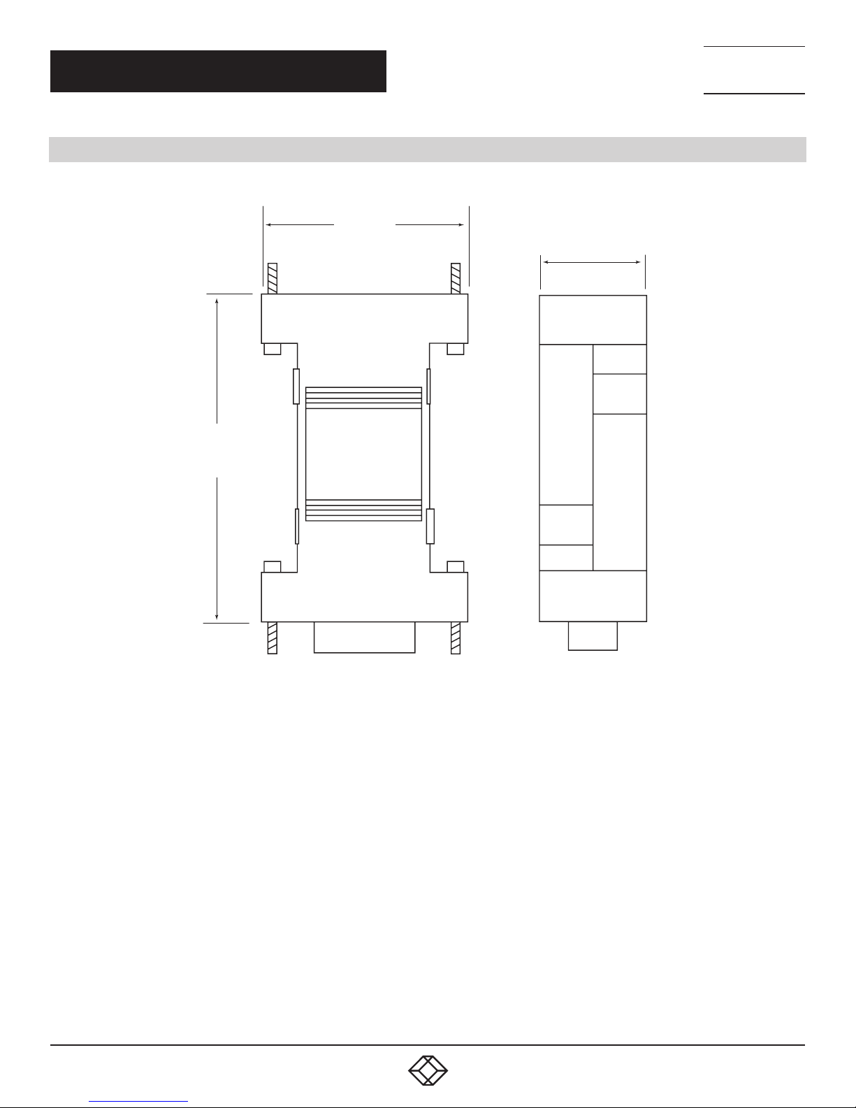
1.2 DIMENSIONAL DIAGRAMS
NEED HELP?
LEAV E TH E TEC H TO US
LIVE 24/7
TECHNICAL
SUPPORT
1. 8 7 7. 8 7 7. 2 2 69
5.8 cm
2.3 in
3.2 cm
1.3 in
1.6 cm
0.6 in
4
FIGURE 1-1. DIMENSIONS
1. 8 7 7. 8 7 7. 2 26 9 BLACKBOX.COM
Page 5

NEED HELP?
LEAV E TH E TEC H TO US
LIVE 24/7
CHAPTER 2: OVERVIEW
2.1 INTRODUCTION
Universal Serial Bus (USB) is the common interface used in today’s PCs, replacing the familiar serial ports. However, many commercial
and industrial devices still use the RS-485 interface. To connect these devices to newer PCs, you need a simple and reliable conversion
solution. The IC830A and IC831A offer this solution in a space saving, USB-port powered package.
Simply plug the converter into an available USB port on your computer or USB hub and install the drivers supplied on CD ROM. The device
will show up as an additional COM port in the Windows Device Manager, which is fully compatible with your Windows applications.
A 3.2-foot (1-meter) USB cable is included.
2.2 FEATURES
Connect RS-485 devices to your USB port
Ideal for field-service applications
Small—fits easily into any laptop bag
USB port powered
USB 2.0 (12 Mbps) compatible
Supports RS-485 data rates up to 921.6 kbps
Works with Windows
TECHNICAL
SUPPORT
1. 8 7 7. 8 7 7. 2 2 69
2.3 WHAT’S INCLUDED
IC830A:
USB 2.0 to RS-485 2-Wire Converter, DB9, 1-Port
3.2-ft. (1-m) USB cable
CD-ROM with drivers
IC831A:
USB 2.0 to RS-485 4-Wire Converter, DB9, 1-Port
3.2-ft. (1-m) USB cable
CD-ROM with drivers
1. 8 7 7. 8 7 7. 2 26 9 BLACKBOX.COM
5
Page 6
CHAPTER 2: OVERVIEW
2.4 HARDWARE DESCRIPTION
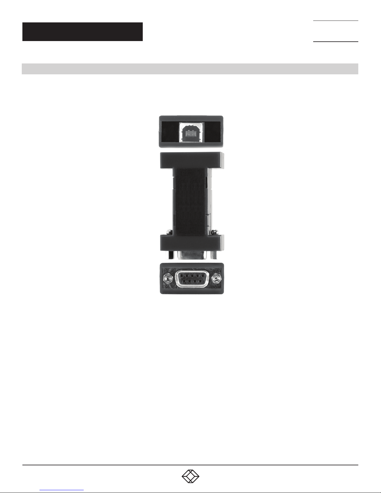
Figure 2-1 shows the converter and describes its components.
USB Type B connector
(links to USB 2.0 interface on PC)
NEED HELP?
LEAV E TH E TEC H TO US
LIVE 24/7
TECHNICAL
SUPPORT
1. 8 7 7. 8 7 7. 2 2 69
DB9 connector
(links to RS-485 interface)
FIGURE 2-1. USB 2.0 TO RS-485 CONVERTER
6
1. 8 7 7. 8 7 7. 2 26 9 BLACKBOX.COM
Page 7
NEED HELP?
LEAV E TH E TEC H TO US
LIVE 24/7
CH APTER 3: I NSTA LL ATIO N
TECHNICAL
SUPPORT
1. 8 7 7. 8 7 7. 2 2 69
3.1 STEP 1: INSTALL THE DRIVERS
CAUTION: To prevent installation errors, do not plug in the hardware until you have already installed the drivers.
The driver software is contained on the CD that is packaged with your converter.
Put the driver CD into the PC. The setup program should automatically launch.
Click “Next.” Accept the license agreement and then click “Next” again.
The program will install the driver and a screen will be displayed indicating successful installation.
When you connect the converter to your PC for the first time, the COM port will be configured. This could take up to 30 seconds.
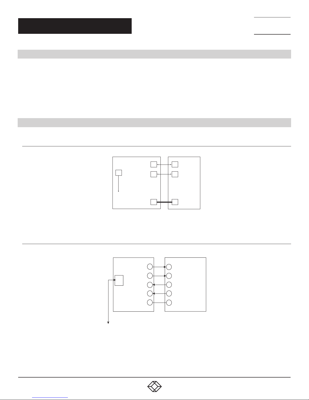
3.2 STEP 2: CONNECT THE CONVERTER
3.2.1 IC830A (2-WIRE)
3.2.2 IC831A (4-WIRE)
PIN 2 Data A (-)
USB
PIN 3 Data B( +)
To PC
PIN 4 GND
IC830A
FIGURE 3-1. IC830A WIRING
Pin 2 RDA(-)
USB
Pin 3 TDB(+)
Pin 7 RDB(+)
Pin 8 TDA(-)
Pin 6 GND
Data A (-)
Data B (+)
GND
RS-485 2-wire device
TDA(-)
RDB(+)
TDB(+)
RDA(-)
GND
IC831A
To PC
RS-485 4-wire device
FIGURE 3-2. IC831A WIRING
1. 8 7 7. 8 7 7. 2 26 9 BLACKBOX.COM
7
Page 8
CH APTER 3: I NSTA LL ATIO N
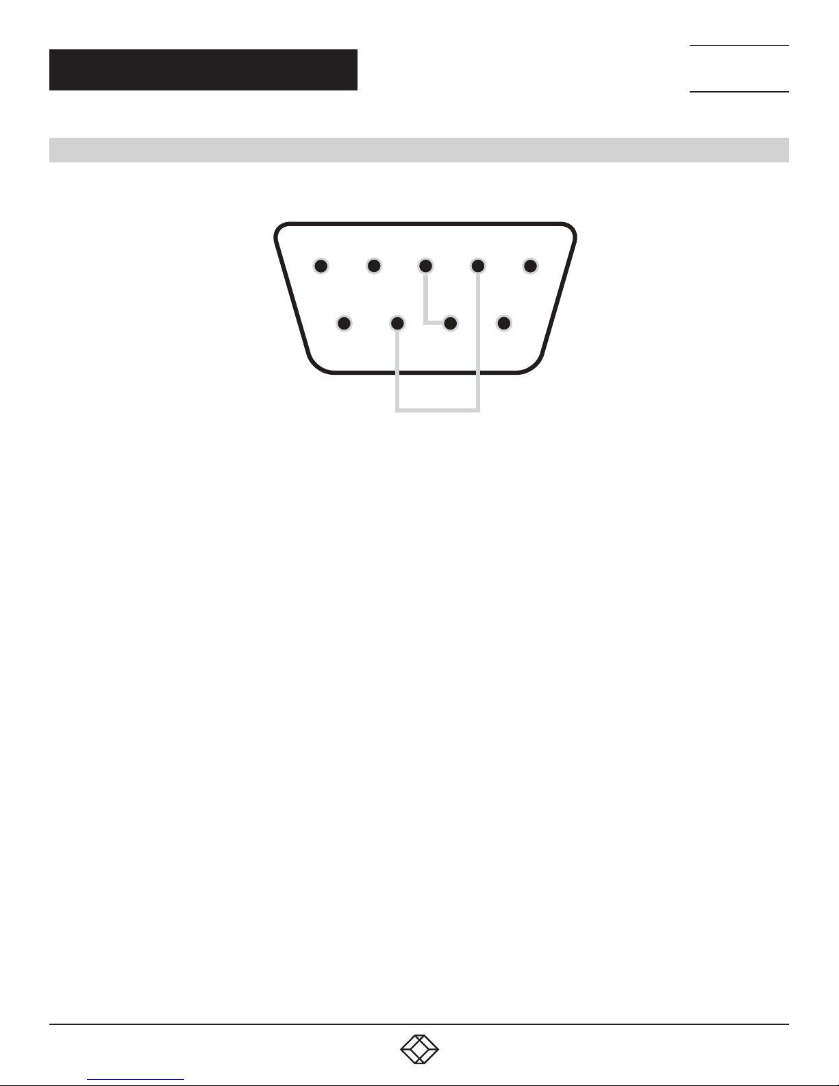
3.3 STEP 3: LOOPBACK TEST (4-WIRE)
Loopback RDA (-) to TDA (-) and TDB (+) to RDB (+) as shown in Figure 3-3.
NEED HELP?
LEAV E TH E TEC H TO US
LIVE 24/7
TECHNICAL
SUPPORT
1. 8 7 7. 8 7 7. 2 2 69
54
98
FIGURE 3-3. LOOPBACK CONNECTIONS
1.Using Hyperterminal or a similar program, connect to the appropriate COM port.
2. Set the desired baud rate.
3. Ensure that Hyperterminal local echo is OFF.
4. Transmit data.
5. If the same character string is returned, the test is good.
3
7
2
6
1
8
1. 8 7 7. 8 7 7. 2 26 9 BLACKBOX.COM
Page 9
NEED HELP?
5
3
1
9
7
LEAV E TH E TEC H TO US
LIVE 24/7
CH APTER 3: I NSTA LL ATIO N
3.4 STEP 4: BACK-TO-BACK TEST (2-WIRE)
Due to the configuration, a loopback test is not possible with the IC830A 2-Wire model. But two converters can be used in a backto-back configuration.
1. Wire the converters.
2. Using Hyperterminal or a similar program, connect to the appropriate COM ports.
3. Set the desired baud rate.
4. Transmit data.
5. If the same string is returned, the test is good.
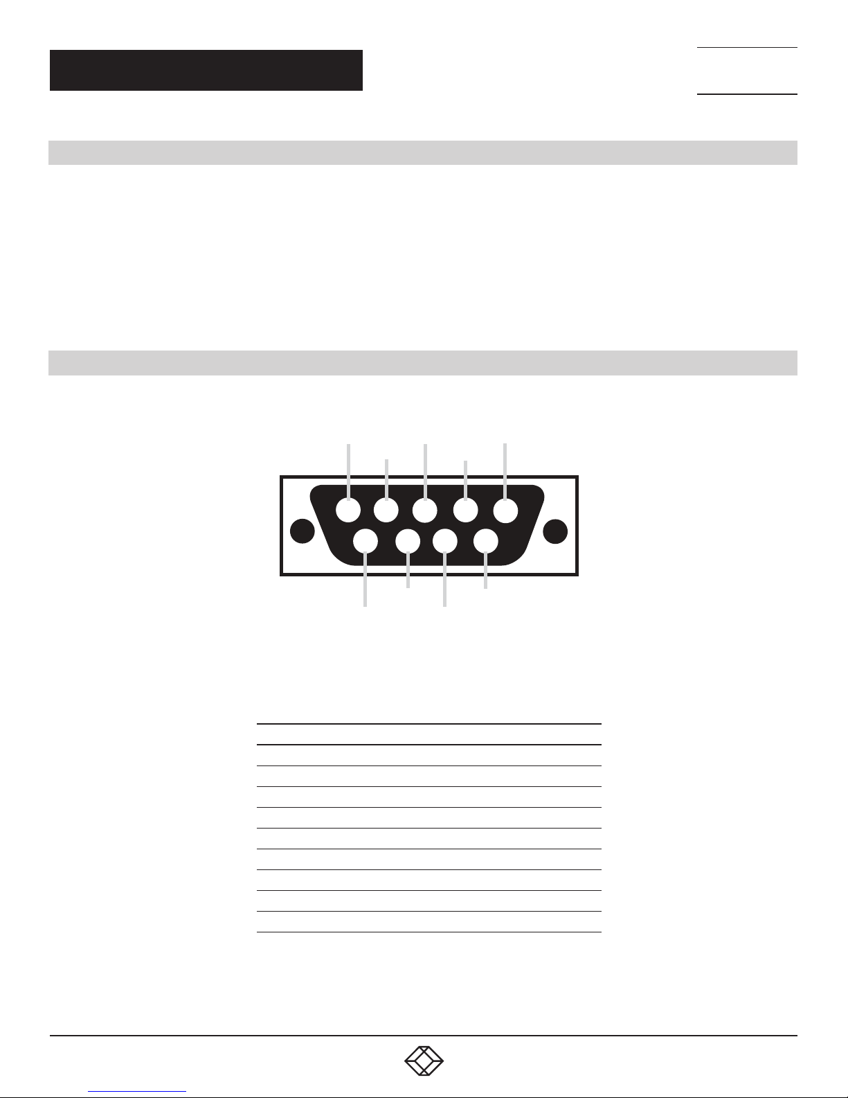
3.5 PINOUTS
Figure 3-4 shows the converter’s DB9 female connector.
TECHNICAL
SUPPORT
1. 8 7 7. 8 7 7. 2 2 69
4
4
5
9
8
8
FIGURE 3-4. DB9 CONNECTOR PINOUT
TABLE 3-1. 2-WIRE AND 4-WIRE PINOUTS
PIN RS-485, 2-WI RE RS-485, 4-W IRE
1 Not used Not used
2 Data A- Input/Output Receive RDA- Input
3 Data B+ Input/Output Transmit TDB+ Output
4 Ground Ground
5 Not used Not used
6 Ground Ground
7 Data B+ Input/Output Receive RDB+ Input
8 Data A- Input/Output Transmit TDA- Output
9 Not used Not used
2
22
3
7
1
6
6
1. 8 7 7. 8 7 7. 2 26 9 BLACKBOX.COM
9
Page 10

NEED HELP?
LEAV E TH E TEC H TO US
LIVE 24/7
CHAPTER 4: OPERATION
Drivers are included on the Compact Disk included with the converter. Simply connect the converter to an available USB port and
insert the CD into the drive. The “Found New Hardware Wizard” will guide you through the installation process. The drivers are not
available via Microsoft Windows Updates. When prompted to connect to Windows Updates to search for drivers, select “No, not at
this time” and follow the instructions for installing from the CD.
When the driver software is installed, the converter will show up in Windows Device Manager as the next available COM port labeled
“RS-485 Port.” Configure the COM port for your application. The default setup is 9600 baud, 8 data bits, no parity, 1 stop bit, no flow
control. The converter will also be listed under USB Controllers.
To uninstall the drivers, follow the instructions contained in the uninstall “read me” file.
Use the IC830A for RS-485 2-Wire systems. In the 2-Wire configuration, the receiver toggles with the transmit data. Bias is provided
by 4.7 KΩ pull-up and pull-down resistors.
Use the IC831A for RS-485 4-Wire systems. In the 4-Wire configuration, the receiver is always active. Bias is provided by 4.7 KΩ pull-
up and pull-down resistors on the receive pair. Bias should be provided on the transmit pair by the end of line slave device.
In most applications, termination is not required. If your application does require termination, it must be installed external to the
converter.
TECHNICAL
SUPPORT
1. 8 7 7. 8 7 7. 2 2 69
10
1. 8 7 7. 8 7 7. 2 26 9 BLACKBOX.COM
Page 11

NEED HELP?
LEAV E TH E TEC H TO US
LIVE 24/7
CHAPTER 5: TROUBLESHOOTING
CHAPTER 1: HEADLINE
TECHNICAL
SUPPORT
1. 8 7 7. 8 7 7. 2 2 69
One USB port is required for each installed device. The USB port can be native to the PC or it can be a USB port on a hub that is
connected to a PC.
To verify the installation:
1. Open the Windows Device Manager.
2. Scroll down to Ports.
3. Expand the flyout window.
4. You should see the new ports. If there are no exclamation points or other trouble indicators, the ports are installed correctly and
ready to use.
1. 8 7 7. 8 7 7. 2 26 9 BLACKBOX.COM
11
Page 12

NEED HELP?
LEAV E TH E TEC H TO US
LIVE 24/7
CHAPTER 1: HEADLINE
APPENDIX A: REGULATORY INFORMATION
TECHNICAL
SUPPORT
1. 8 7 7. 8 7 7. 2 2 69
A.1 FCC STATEMENT
This equipment generates, uses, and can radiate radio-frequency energy, and if not installed and used properly, that is, in strict
accordance with the manufacturer’s instructions, may cause inter ference to radio communication. It has been tested and found to
comply with the limits for a Class A computing device in accordance with the specifications in Subpart B of Part 15 of FCC rules,
which are designed to provide reasonable protection against such interference when the equipment is operated in a commercial
environment. Operation of this equipment in a residential area is likely to cause interference, in which case the user at his own
expense will be required to take whatever measures may be necessary to correct the interference.
Changes or modifications not expressly approved by the party responsible for compliance could void the user’s authority to operate
the equipment.
This digital apparatus does not exceed the Class A limits for radio noise emis sion from digital apparatus set out in the Radio
Interference Regulation of Industry Canada.
Le présent appareil numérique n’émet pas de bruits radioélectriques dépassant les limites applicables aux appareils numériques
de classe A prescrites dans le Règlement sur le brouillage radioélectrique publié par Industrie Canada.
A.2 CE DECLARATION OF CONFORMITY
This equipment complies with CE standards EN 55022, EN 61000-6-1, and EN 61000 (-4-2, -4-3, -4-4, -4-5, -4-6, -4-8, -4-11).
12
1. 8 7 7. 8 7 7. 2 26 9 BLACKBOX.COM
Page 13

NEED HELP?
LEAV E TH E TEC H TO US
LIVE 24/7
APPENDIX A: REGULATORY INFORMATION
TECHNICAL
SUPPORT
1. 8 7 7. 8 7 7. 2 2 69
A.3 NOM STATEMENT
1. Todas las instrucciones de seguridad y operación deberán ser leídas antes de que el aparato eléctrico sea operado.
2. Las instrucciones de seguridad y operación deberán ser guardadas para referencia futura.
3. Todas las advertencias en el aparato eléctrico y en sus instrucciones de operación deben ser respetadas.
4. Todas las instrucciones de operación y uso deben ser seguidas.
5. El aparato eléctrico no deberá ser usado cerca del agua—por ejemplo, cerca de la tina de baño, lavabo, sótano mojado o cerca de
una alberca, etc.
6. El aparato eléctrico debe ser usado únicamente con carritos o pedestales que sean recomendados por el fabricante.
7. El aparato eléctrico debe ser montado a la pared o al techo sólo como sea recomendado por el fabricante.
8. Servicio—El usuario no debe intentar dar servicio al equipo eléctrico más allá a lo descrito en las instrucciones de operación.
Todo otro servicio deberá ser referido a personal de servicio calificado.
9. El aparato eléctrico debe ser situado de tal manera que su posición no interfiera su uso. La colocación del aparato eléctrico
sobre una cama, sofá, alfombra o superficie similar puede bloquea la ventilación, no se debe colocar en libreros o gabinetes que
impidan el flujo de aire por los orificios de ventilación.
10. El equipo eléctrico deber ser situado fuera del alcance de fuentes de calor como radiadores, registros de calor, estufas u otros
aparatos (incluyendo amplificadores) que producen calor.
11. El aparato eléctrico deberá ser connectado a una fuente de poder sólo del tipo descrito en el instructivo de operación, o como
se indique en el aparato.
12. Precaución debe ser tomada de tal manera que la tierra fisica y la polarización del equipo no sea eliminada.
13. Los cables de la fuente de poder deben ser guiados de tal manera que no sean pisados ni pellizcados por objetos colocados
sobre o contra ellos, poniendo particular atención a los contactos y receptáculos donde salen del aparato.
14. El equipo eléctrico debe ser limpiado únicamente de acuerdo a las recomendaciones del fabricante.
15. En caso de existir, una antena externa deberá ser localizada lejos de las lineas de energia.
16. El cable de corriente deberá ser desconectado del cuando el equipo no sea usado por un largo periodo de tiempo.
17. Cuidado debe ser tomado de tal manera que objectos liquidos no sean derramados sobre la cubierta u orificios de ventilación.
18. Servicio por personal calificado deberá ser provisto cuando:
A: El cable de poder o el contacto ha sido dañado; u
B: Objectos han caído o líquido ha sido derramado dentro del aparato;o
C: El aparato ha sido expuesto a la lluvia; o
D: El aparato parece no operar normalmente o muestra un cambio en su desempeño; o
E: El aparato ha sido tirado o su cubierta ha sido dañada.
1. 8 7 7. 8 7 7. 2 26 9 BLACKBOX.COM
13
Page 14

NEED HELP?
LEAV E TH E TEC H TO US
LIVE 24/7
CHAPTER 1: HEADLINE
APPENDIX B: DISCLAIMER/TRADEMARKS
TECHNICAL
SUPPORT
1. 8 7 7. 8 7 7. 2 2 69
B.1 DISCLAIMER
Black Box Corporation shall not be liable for damages of any kind, including, but not limited to, punitive, consequential or cost of cover
damages, resulting from any errors in the product information or specifications set forth in this document and Black Box Corporation
may revise this document at any time without notice.
B.2 TRADEMARKS USED IN THIS MANUAL
Black Box Corporation and the logo type and mark are registered trademarks of Black Box Corporation.
Any other trademarks mentioned in this manual are acknowledged to be the property of the trademark owners.
14
1. 8 7 7. 8 7 7. 2 26 9 BLACKBOX.COM
Page 15

NOTES
__________________________________________________________________________________________________
__________________________________________________________________________________________________
__________________________________________________________________________________________________
__________________________________________________________________________________________________
__________________________________________________________________________________________________
__________________________________________________________________________________________________
NEED HELP?
LEAV E TH E TEC H TO US
LIVE 24/7
TECHNICAL
SUPPORT
1. 8 7 7. 8 7 7. 2 2 69
__________________________________________________________________________________________________
_
_________________________________________________________________________________________________
__________________________________________________________________________________________________
__________________________________________________________________________________________________\
__________________________________________________________________________________________________
__________________________________________________________________________________________________
__________________________________________________________________________________________________
__________________________________________________________________________________________________
_________________________________________________________________________________________________
__________________________________________________________________________________________________
__________________________________________________________________________________________________
1. 8 7 7. 8 7 7. 2 26 9 BLACKBOX.COM
15
Page 16

NEED HELP?
LEAVE THE TECH TO US
LIVE 24/7
TECHNICAL
SUPPORT
1.877.877. 2 2 69
© COPYRIGHT 2017 BLACK BOX CORPORATION. ALL RIGHTS RESERVED.
 Loading...