

APRIL 1991
IC720A
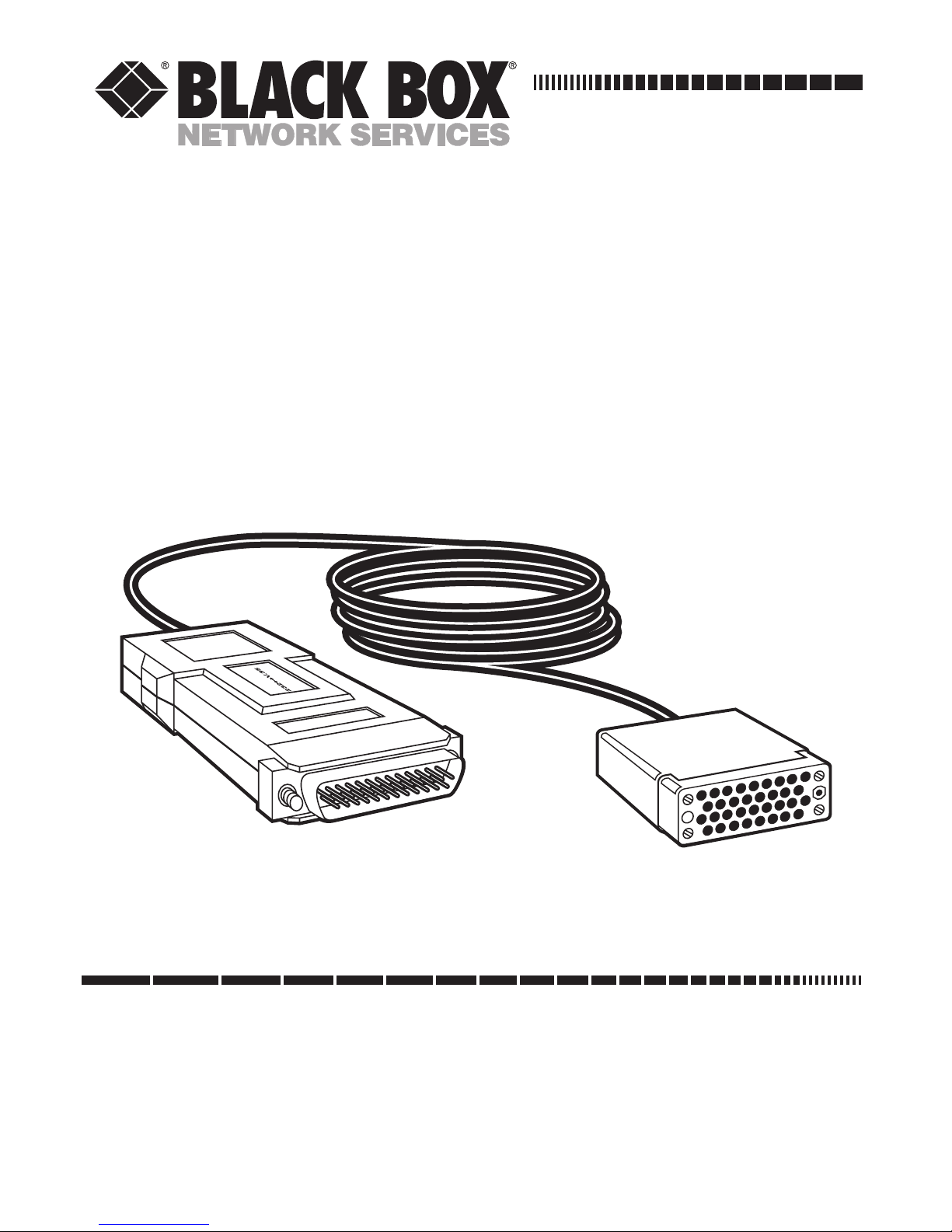
V.24↔V.35
Interface Converter
CUSTOMER SUPPORT INFORMATION
Order toll-free in the U.S.: Call 877-877-BBOX (outside U.S. call 724-746-5500)
FREE technical support 24 hours a day, 7 days a week: Call 724-746-5500 or fax 724-746-0746
Mailing address: Black Box Corporation, 1000 Park Drive, Lawrence, PA 15055-1018
Web site: www.blackbox.com • E-mail: info@blackbox.com

1
FCC STATEMENT
FEDERAL COMMUNICATIONS COMMISSION
AND
INDUSTRY CANADA
RADIO FREQUENCY INTERFERENCE STATEMENTS
This equipment generates, uses, and can radiate radio-frequency energy,
and if not installed and used properly, that is, in strict accordance with the
manufacturer’s instructions, may cause interference to radio communication.
It has been tested and found to comply with the limits for a Class A computing
device in accordance with the specifications in Subpart B of Part 15 of FCC rules,
which are designed to provide reasonable protection against such interference
when the equipment is operated in a commercial environment. Operation of
this equipment in a residential area is likely to cause interference, in which case
the user at his own expense will be required to take whatever measures may be
necessary to correct the interference.
Changes or modifications not expressly approved by the party responsible
for compliance could void the user’s authority to operate the equipment.
This digital apparatus does not exceed the Class A limits for radio noise emission from
digital apparatus set out in the Radio Interference Regulation of Industry Canada.
Le présent appareil numérique n’émet pas de bruits radioélectriques dépassant les limites
applicables aux appareils numériques de classe A prescrites dans le Règlement sur le
brouillage radioélectrique publié par Industrie Canada.

2
V.24↔V.35 INTERFACE CONVERTER
NORMAS OFICIALES MEXICANAS (NOM)
ELECTRICAL SAFETY STATEMENT
INSTRUCCIONES DE SEGURIDAD
1. Todas las instrucciones de seguridad y operación deberán ser leídas antes
de que el aparato eléctrico sea operado.
2. Las instrucciones de seguridad y operación deberán ser guardadas para
referencia futura.
3. Todas las advertencias en el aparato eléctrico y en sus instrucciones de
operación deben ser respetadas.
4. Todas las instrucciones de operación y uso deben ser seguidas.
5. El aparato eléctrico no deberá ser usado cerca del agua—por ejemplo,
cerca de la tina de baño, lavabo, sótano mojado o cerca de una alberca,
etc..
6. El aparato eléctrico debe ser usado únicamente con carritos o pedestales
que sean recomendados por el fabricante.
7. El aparato eléctrico debe ser montado a la pared o al techo sólo como sea
recomendado por el fabricante.
8. Servicio—El usuario no debe intentar dar servicio al equipo eléctrico más
allá a lo descrito en las instrucciones de operación. Todo otro servicio
deberá ser referido a personal de servicio calificado.
9. El aparato eléctrico debe ser situado de tal manera que su posición no
interfiera su uso. La colocación del aparato eléctrico sobre una cama,
sofá, alfombra o superficie similar puede bloquea la ventilación, no se
debe colocar en libreros o gabinetes que impidan el flujo de aire por los
orificios de ventilación.

3
NOM STATEMENT
10. El equipo eléctrico deber ser situado fuera del alcance de fuentes de calor
como radiadores, registros de calor, estufas u otros aparatos (incluyendo
amplificadores) que producen calor.
11. El aparato eléctrico deberá ser connectado a una fuente de poder sólo del
tipo descrito en el instructivo de operación, o como se indique en el
aparato.
12. Precaución debe ser tomada de tal manera que la tierra fisica y la
polarización del equipo no sea eliminada.
13. Los cables de la fuente de poder deben ser guiados de tal manera que no
sean pisados ni pellizcados por objetos colocados sobre o contra ellos,
poniendo particular atención a los contactos y receptáculos donde salen
del aparato.
14. El equipo eléctrico debe ser limpiado únicamente de acuerdo a las
recomendaciones del fabricante.
15. En caso de existir, una antena externa deberá ser localizada lejos de las
lineas de energia.
16. El cable de corriente deberá ser desconectado del cuando el equipo no
sea usado por un largo periodo de tiempo.
17. Cuidado debe ser tomado de tal manera que objectos liquidos no sean
derramados sobre la cubierta u orificios de ventilación.
18. Servicio por personal calificado deberá ser provisto cuando:
A: El cable de poder o el contacto ha sido dañado; u
B: Objectos han caído o líquido ha sido derramado dentro del
aparato; o
C: El aparato ha sido expuesto a la lluvia; o
D: El aparato parece no operar normalmente o muestra un cambio en
su desempeño; o
E: El aparato ha sido tirado o su cubierta ha sido dañada.

4
V.24↔V.35 INTERFACE CONVERTER
TRADEMARKS USED IN THIS MANUAL
Any trademarks mentioned in this manual are acknowledged
to be the property of the trademark owners.

5
TABLE OF CONTENTS
Contents
Chapter Page
1. Specifications . . . . . . . . . . . . . . . . . . . . . . . . . . . . 6
2. Introduction. . . . . . . . . . . . . . . . . . . . . . . . . . . . . 8
3. Configuration and Installation. . . . . . . . . . . . . 10
4. Schematic Diagrams . . . . . . . . . . . . . . . . . . . . . 13

6
V.24↔V.35 INTERFACE CONVERTER
1. Specifications
Speed — Up to 64 kbps
Maximum Distance
— 6.5 ft. (2 m)
Operation
— Synchronous
Leads Supported
— V.35: A, B, C, D, E, F, H, P, R, S, T,
U, V, W, X, Y, AA;
V.24/RS-232: 1, 2, 3, 4, 5, 6, 7, 8, 15, 17, 20, 24
Indicators
— None
Flow Control
— Provided by attached devices
(transparent to protocol)
Interface
— V.24/RS-232 and V.35; both DTE/DCE
shunt-selectable
Connectors
— V.24: DB25 (male);
V.35: 34-pin (male or female)

7
CHAPTER 1: Specifications
Power — Derives power from interface
Size
— 0.9"H x 2.1"W x 4.3"D (2.3 x 5.3 x 10.9 cm)
Weight
— 0.9 lb. (0.4 kg), including cable and
connectors

8
V.24↔V.35 INTERFACE CONVERTER
2. Introduction
The V.24↔V.35 Interface Converter connects two data
communications products: one has a V.24 interface and
the other has a V.35 interface. The converter is used in
synchronous applications and operates at data rates up
to 64 kbps. It converts the physical as well as the
electrical interfaces. Its circuitry converts the interface
within short range – use the converter to connect
devices located close to each other (less than 6.5 feet
[2 m] apart).
The converter operates without AC power, using ultralow power from the DTE and DCE equipment data and
control signals. It is switch-selectable for one of the
following two applications:
• Connecting a V.24 (RS-232) DTE to a V.35 DCE
• Connecting a V.24 (RS-232) DCE to a V.35 DTE
The converter offers these features:
• Cable and connectors are built into a single unit
• Transparent to protocol

9
CHAPTER 2: Introduction
• Operates at speeds up to 64 kbps
• Quick and easy install
• Works without AC power
• Compact and lightweight

10
V.24↔V.35 INTERFACE CONVERTER
3. Configuration and Installation
The converter installs between an RS-232 device
configured as DTE or DCE and a V.35 device configured
as DCE or DTE. (If one device is configured as DTE,
the other device must be configured as DCE, and vice
versa.) You configure the cable to fit your equipment by
moving a jumper on the circuit board inside the RS-232
connector. A typical application appears in Figure 1.
Figure 1. Typical Application of the V.24↔V.35 Interface Converter.
DTE
Synchronous
Terminal
Synchronous Modem
or Multiplexor
Interface X
(V.24)
Interface Y
(V.35)
DCE

11
CHAPTER 3: Configuration and Installation
The converter is factory-strapped for V.24 DTE/V.35
DCE as shown in Figure 2.
Figure 2. V.24 DTE , V.35 DCE.
To configure the cable for V.35 DTE/V.24 DCE, follow
these steps:
1. Locate the RS-232 connector on the cable.
2. To remove the cover of the connector, press in on the
four tabs located on each side of the connector and lift
the top half of the cover from the bottom half.
3. Locate the 40-pin DTE/DCE socket on the connector
circuit board. Figure 2 illustrates the board’s factory
configuration.

12
V.24↔V.35 INTERFACE CONVERTER
4. Remove the DTE/DCE socket by gently grasping both
sides and slowly moving it from side to side.
5. Turn the socket around and replace it so that the DCE
side (labeled on the socket) faces the V.24 connector of
the cable and the DTE faces the V.35 device (see Figure
3). Make sure that the pins are aligned with the socket.
Figure 3. V.35 DTE, V.24 DCE.
6. To close the unit, press the two plastic covers together.
To install the converter, plug the RS-232 connector into
your RS-232 device and plug the V.35 connector into
your V.35 device. The converter is now ready for
operation.

13
CHAPTER 4: Schematic Diagrams
4. Schematic Diagrams
The following diagrams apply to V.35 DTE/V.24 DCE
and V.24 DTE/V.35 DCE configurations.

14
V.24↔V.35 INTERFACE CONVERTER
Figure 4. V.35 DTE/V.24 DCE.
*NOTE: DTE/DCE defines the device to which the converter is
attached, not the converter.

15
CHAPTER 4: Schematic Diagrams
Figure 5. V.24 DTE/V.35 DCE.
*NOTE: DTE/DCE defines the device to which the converter is
attached, not the converter.

1000 Park Drive • Lawrence, PA 15055-1018 • 724-746-5500 • Fax 724-746-0746
© Copyright 1991. Black Box Corporation. All rights reserved.
 Loading...