

Order toll-free in the U.S.: Call 877-877-BBOX (outside U.S. call 724-746-5500)
FREE technical support 24 hours a day, 7 days a week: Call 724-746-5500 or fax 724-746-0746
Mailing address: Black Box Corporation, 1000 Park Drive, Lawrence, PA 15055-1018
Web site: www.blackbox.com • E-mail: info@blackbox.com
CUSTOMER
SUPPORT
INFORMATION
JANUARY 1997
IC716A
IC716A-RJ
IC716C
RM110A
G.703 Rate and Interface Converters

FCC STATEMENT
1
FEDERAL COMMUNICATIONS COMMISSION
AND
INDUSTRY CANADA
RADIO FREQUENCY INTERFERENCE STATEMENTS
This equipment generates, uses, and can radiate radio-frequency energy, and if not installed and used
properly, that is, in strict accordance with the manufacturer’s instructions, may cause interference to radio
communication. It has been tested and found to comply with the limits for a Class A computing device in
accordance with the specifications in Subpart B of Part 15 of FCC rules, which are designed to provide
reasonable protection against such interference when the equipment is operated in a commercial
environment. Operation of this equipment in a residential area is likely to cause interference, in which
case the user at his own expense will be required to take whatever measures may be necessary to correct
the interference.
Changes or modifications not expressly approved by the party responsible for compliance could void the user’s
authority to operate the equipment.
This digital apparatus does not exceed the Class A limits for radio noise emission from digital apparatus set out in the Radio
Interference Regulation of Industry Canada.
Le présent appareil numérique n’émet pas de bruits radioélectriques dépassant les limites applicables aux appareils numériques
de la classe A prescrites dans le Règlement sur le brouillage radioélectrique publié par Industrie Canada.

G.703 RATE AND INTERFACE CONVERTERS
2
INSTRUCCIONES DE SEGURIDAD (Normas Oficiales Mexicanas Electrical Safety Statement)
1. Todas las instrucciones de seguridad y operación deberán ser leídas antes de que el aparato eléctrico sea operado.
2. Las instrucciones de seguridad y operación deberán ser guardadas para referencia futura.
3. Todas las advertencias en el aparato eléctrico y en sus instrucciones de operación deben ser respetadas.
4. Todas las instrucciones de operación y uso deben ser seguidas.
5. El aparato eléctrico no deberá ser usado cerca del agua—por ejemplo, cerca de la tina de baño, lavabo, sótano
mojado o cerca de una alberca, etc..
6. El aparato eléctrico debe ser usado únicamente con carritos o pedestales que sean recomendados por el fabricante.
7. El aparato eléctrico debe ser montado a la pared o al techo sólo como sea recomendado por el fabricante.
8. Servicio—El usuario no debe intentar dar servicio al equipo eléctrico más allá a lo descrito en las instrucciones de
operación. Todo otro servicio deberá ser referido a personal de servicio calificado.
9. El aparato eléctrico debe ser situado de tal manera que su posición no interfiera su uso. La colocación del aparato
eléctrico sobre una cama, sofá, alfombra o superficie similar puede bloquea la ventilación, no se debe colocar en
libreros o gabinetes que impidan el flujo de aire por los orificios de ventilación.
10. El equipo eléctrico deber ser situado fuera del alcance de fuentes de calor como radiadores, registros de calor, estufas
u otros aparatos (incluyendo amplificadores) que producen calor.
11. El aparato eléctrico deberá ser connectado a una fuente de poder sólo del tipo descrito en el instructivo de
operación, o como se indique en el aparato.
12. Precaución debe ser tomada de tal manera que la tierra fisica y la polarización del equipo no sea eliminada.
13. Los cables de la fuente de poder deben ser guiados de tal manera que no sean pisados ni pellizcados por objetos
colocados sobre o contra ellos, poniendo particular atención a los contactos y receptáculos donde salen del aparato.
14. El equipo eléctrico debe ser limpiado únicamente de acuerdo a las recomendaciones del fabricante.
15. En caso de existir, una antena externa deberá ser localizada lejos de las lineas de energia.
16. El cable de corriente deberá ser desconectado del cuando el equipo no sea usado por un largo periodo de tiempo.
17. Cuidado debe ser tomado de tal manera que objectos liquidos no sean derramados sobre la cubierta u orificios de
ventilación.
18. Servicio por personal calificado deberá ser provisto cuando:
A: El cable de poder o el contacto ha sido dañado; u
B: Objectos han caído o líquido ha sido derramado dentro del aparato; o
C: El aparato ha sido expuesto a la lluvia; o
D: El aparato parece no operar normalmente o muestra un cambio en su desempeño; o
E: El aparato ha sido tirado o su cubierta ha sido dañada.

TRADEMARK
3
TRADEMARKS USED IN THIS MANUAL
Any trademarks mentioned in this manual are acknowledged to be the property of the trademark owners.
WARNING!
Always observe standard safety precautions during installation, operation, and
maintenance of this product. To avoid the possibility of electrical shock, disconnect the
power cord from the power source before you open up the unit or perform any repairs.

G.703 RATE AND INTERFACE CONVERTERS
4
Contents
Chapter Page
1. Specifications . . . . . . . . . . . . . . . . . . . . . . . . . . . . . . . . . . . . . . . . . . . . . . . . . . . . . . . . . . . . . . . . . . . . . . . .5
2. Introduction . . . . . . . . . . . . . . . . . . . . . . . . . . . . . . . . . . . . . . . . . . . . . . . . . . . . . . . . . . . . . . . . . . . . . . . . .7
2.1 General Description . . . . . . . . . . . . . . . . . . . . . . . . . . . . . . . . . . . . . . . . . . . . . . . . . . . . . . . . . . . . . .7
2.2 Functional Description . . . . . . . . . . . . . . . . . . . . . . . . . . . . . . . . . . . . . . . . . . . . . . . . . . . . . . . . . . . .8
2.2.1 G.703 Interface . . . . . . . . . . . . . . . . . . . . . . . . . . . . . . . . . . . . . . . . . . . . . . . . . . . . . . . . . . .8
2.2.2 Rate Adapter . . . . . . . . . . . . . . . . . . . . . . . . . . . . . . . . . . . . . . . . . . . . . . . . . . . . . . . . . . . .9
2.2.3 Async/Sync Converter and V.54 Circuits . . . . . . . . . . . . . . . . . . . . . . . . . . . . . . . . . . . . . .9
2.2.4 Transmit FIFO . . . . . . . . . . . . . . . . . . . . . . . . . . . . . . . . . . . . . . . . . . . . . . . . . . . . . . . . . . .9
2.2.5 RS-232 Interface . . . . . . . . . . . . . . . . . . . . . . . . . . . . . . . . . . . . . . . . . . . . . . . . . . . . . . . . . .9
3. Installation . . . . . . . . . . . . . . . . . . . . . . . . . . . . . . . . . . . . . . . . . . . . . . . . . . . . . . . . . . . . . . . . . . . . . . . . .11
3.1 Site Preparation . . . . . . . . . . . . . . . . . . . . . . . . . . . . . . . . . . . . . . . . . . . . . . . . . . . . . . . . . . . . . . . .11
3.2 Mechanical Assembly . . . . . . . . . . . . . . . . . . . . . . . . . . . . . . . . . . . . . . . . . . . . . . . . . . . . . . . . . . . .11
3.3 Electrical Installation . . . . . . . . . . . . . . . . . . . . . . . . . . . . . . . . . . . . . . . . . . . . . . . . . . . . . . . . . . . .11
3.3.1 Power Connection . . . . . . . . . . . . . . . . . . . . . . . . . . . . . . . . . . . . . . . . . . . . . . . . . . . . . . .11
3.3.2 Rear-Panel Connectors . . . . . . . . . . . . . . . . . . . . . . . . . . . . . . . . . . . . . . . . . . . . . . . . . . .12
3.3.3 Strap Selection . . . . . . . . . . . . . . . . . . . . . . . . . . . . . . . . . . . . . . . . . . . . . . . . . . . . . . . . . .12
3.3.4 Installing the Internal Jumpers and Switches . . . . . . . . . . . . . . . . . . . . . . . . . . . . . . . . .12
4. Operation . . . . . . . . . . . . . . . . . . . . . . . . . . . . . . . . . . . . . . . . . . . . . . . . . . . . . . . . . . . . . . . . . . . . . . . . . .15
4.1 Buttons and Indicators . . . . . . . . . . . . . . . . . . . . . . . . . . . . . . . . . . . . . . . . . . . . . . . . . . . . . . . . . . .15
4.2 Operating Procedure . . . . . . . . . . . . . . . . . . . . . . . . . . . . . . . . . . . . . . . . . . . . . . . . . . . . . . . . . . . .16
4.2.1 Powering On . . . . . . . . . . . . . . . . . . . . . . . . . . . . . . . . . . . . . . . . . . . . . . . . . . . . . . . . . . .16
4.2.2 Testing . . . . . . . . . . . . . . . . . . . . . . . . . . . . . . . . . . . . . . . . . . . . . . . . . . . . . . . . . . . . . . . .16
4.3 Reconfiguring the G.703 Rate and Interface Converter . . . . . . . . . . . . . . . . . . . . . . . . . . . . . . . .16
5. Tests and Diagnostics . . . . . . . . . . . . . . . . . . . . . . . . . . . . . . . . . . . . . . . . . . . . . . . . . . . . . . . . . . . . . . . . .17
5.1 Loop Tests (DIG, ANA, and REM) . . . . . . . . . . . . . . . . . . . . . . . . . . . . . . . . . . . . . . . . . . . . . . . . .17
5.2 Self-Test . . . . . . . . . . . . . . . . . . . . . . . . . . . . . . . . . . . . . . . . . . . . . . . . . . . . . . . . . . . . . . . . . . . . . . .17
5.3 Local Test—Local Loopback . . . . . . . . . . . . . . . . . . . . . . . . . . . . . . . . . . . . . . . . . . . . . . . . . . . . . .17
5.4 Communication Link Tests . . . . . . . . . . . . . . . . . . . . . . . . . . . . . . . . . . . . . . . . . . . . . . . . . . . . . . .18
5.4.1 Remote Digital Loopback . . . . . . . . . . . . . . . . . . . . . . . . . . . . . . . . . . . . . . . . . . . . . . . . .18
5.4.2 Local Digital Loopback . . . . . . . . . . . . . . . . . . . . . . . . . . . . . . . . . . . . . . . . . . . . . . . . . . .19
Appendix A. The RM110A Rack and the G.703 Rate and Interface Converter Card . . . . . . . . . . . . . . . .20
A.1 Rack Description . . . . . . . . . . . . . . . . . . . . . . . . . . . . . . . . . . . . . . . . . . . . . . . . . . . . . . . . . . . . . . .20
A.2 Power Supply . . . . . . . . . . . . . . . . . . . . . . . . . . . . . . . . . . . . . . . . . . . . . . . . . . . . . . . . . . . . . . . . . .21
A.3 Installation . . . . . . . . . . . . . . . . . . . . . . . . . . . . . . . . . . . . . . . . . . . . . . . . . . . . . . . . . . . . . . . . . . . .21
A.4 Operation . . . . . . . . . . . . . . . . . . . . . . . . . . . . . . . . . . . . . . . . . . . . . . . . . . . . . . . . . . . . . . . . . . . . .21
Appendix B. V.24/RS-232 Interconnection . . . . . . . . . . . . . . . . . . . . . . . . . . . . . . . . . . . . . . . . . . . . . . . . .22
Appendix C. Rack Adapter Installation Kits . . . . . . . . . . . . . . . . . . . . . . . . . . . . . . . . . . . . . . . . . . . . . . . . .24
C.1 Rack Adapter Kit—Single-Unit Installation . . . . . . . . . . . . . . . . . . . . . . . . . . . . . . . . . . . . . . . . . .24
C.2 Rack Adapter Kit—Dual-Unit Installation . . . . . . . . . . . . . . . . . . . . . . . . . . . . . . . . . . . . . . . . . . .25

CHAPTER 1: Specifications
5
1. Specifications
Interface — Codirectional, 64 Kbps; connects to an EIA RS-232/CCITT V.24
terminal interface
Line — 4-wire
Maximum Range — Up to 0.5 miles (800 m) over 24 gauge
Data Rates — 600, 1200, 2400, 4800, 7200, 9600, 14,400, 19,200 bps
Character Length in Async Mode — Selectable 8, 9, 10, 11 (includes Start+Stop+Parity+Character
Bits)
Control Signals — RTS, DTR, DCD, DSR, CTS are passed through according to
CCITT I.463; DSR may be set to constantly ON (strapselectable)
Impedance — 120Ω balanced
Protocol — Sync or async, full duplex
Connectors — IC716A: (1) 5-screw terminal block; IC716A-RJ: (1) RJ-45
female; Both: (1) DB25 female
Diagnostics — Front-panel pushbuttons DIG (Local Digital Loopback), ANA
(Local Analog Loopback), REM (Remote Digital Loopback),
or (V.54) activated from RS-232/V.24 DTE; DIG is activated by
a manual switch; REM is activated by a manual switch or by the
DTE interface signal (Pin 21); ANA is activated by a manual
switch or by the DTE interface signal (Pin 18)
Indicators — (7) LEDs: PWR, RTS, TD, RD, TEST, G.703 SYNC LOSS,
V.110 SYNC LOSS
Balance — Better than 45 dB (up to 256 KHz)
Timing Elements — Transmit clock (derived from 3 alternative sources: Internal
oscillator, external from the DTE [Pin 24] low-speed clock,
and loop clock derived from the receive signal, looped back
as a transmit clock) and low-speed clock (the DCE low-speed
timing signal [pins 15 and 17] is derived from the 64-KHz
clock)
Return Loss — Better than 20 dB (up to 256 KHz); Better than 14 dB
(up to 384 KHz)
Clock Frequency — 64 KHz
Frequency Tracking — ±500 ppm
“Pulse” Amplitude — 1.0V nominal
“Zero” Amplitude — 0V±0.1V maximum
Operating Temperature — 32 to 122°F (0 to 50°C)

G.703 RATE AND INTERFACE CONVERTERS
6
Relative Humidity Tolerance — 10 to 90%, noncondensing
Power — 115 VAC (230-VAC version available)±10%, 47 to 63 Hz, 3 watts;
0.1 A slow-blow fuse; AC/DC overvoltage protection, connected
via transformers to transmit or receive telephone lines (or
coaxial cable)
Size — IC716A, IC716A-RJ: 1.8"H x 7.6"W x 9.5"D (4.6 x 19.3 x
24.1 cm); IC716C: 9"H x 6.2"W x 1"D (22.9 x 15.8 x 2.5 cm)
Weight — IC716A, IC716A-RJ: 3.1 lb. (1.4 kg); IC716C: 0.6 lb. (0.3 kg)

CHAPTER 2: Introduction
7
2. Introduction
2.1 General Description
The G.703 Rate and Interface Converter allows low-speed V.24 equipment to be connected to a G.703
codirectional (64 Kbps) interface. This conversion enables connection of low-speed data channels to the
PCM network. The rate conversion is performed according to CCITT I.463 (V.110) and I.460 standards.
This rate conversion also enables access to ISDN terminal adapters through the telecommunication
network.
The Converter operates synchronously or asynchronously, converting V.24 rates up to 19,200 bps. For
async rates of 600 bps and higher, the async-to-sync conversion is compatible with CCITT V.14. For async
rates lower than 600 bps, the Converter operates in synchronous mode at 19,200 bps and multi-samples
the data.
Operating full duplex at a transmission rate of 64 Kbps, the Converter has a range of up to a half mile
(800 m) from the G.703 equipment. The high-speed transmit timing source is strap-selectable for either
recovered clock from the G.703 interface, external timing from the V.24 interface, or internal timing.
The Converter features V.54 diagnostic capabilities for performing local loopback and remote digital
loopback. When in the digital loopback mode, the operator at either end of the line may test both units
and the line. The loopback is controlled either by front-panel buttons or by Pins 18 and 21 of the
V.24/RS-232 interface.
All V.24 configuration parameters—such as bit rate, bit length, and sync/async—can be selected at each
Interface Converter. Alternatively, parameters can be selected at a “master” Interface Converter, and
downline-loaded from the “master” to a “slave” Interface Converter.
The control signals RTS and DTR are passed through end-to-end to DCD and DSR, respectively, in
compliance with CCITT I.463 (V.110). DSR can be optionally set separately to be continuously ON.
The Converter is coupled to the G.703 4-wire interface line through isolation transformers which, in
conjunction with other circuitry, protect against AC or DC overvoltages. The protection circuitry enables
operation even when DC is connected to the line.
The Interface Converter is available as a desktop unit (with either terminal blocks or RJ-45 connectors)
or as a rackmount card for a 19-inch rack. The RM110A rack (power supply 100 VA) can carry up to
fourteen cards. Special hardware for mounting standalone units in a 19-inch rack can be ordered
separately. The special hardware enables installation of either one or two units side by side. The unit
height is only 1U (1.75"), requiring minimal rack space.

G.703 RATE AND INTERFACE CONVERTERS
8
2.2 Functional Description
When reading this section refer to the diagram below.
Figure 2-1. G.703 Rate and Interface Converter Block Diagram.
2.2.1 G.703 I
NTERFACE
The G.703 interface on the transmit side converts the analog transmit signal to a three-level signal, and
inserts a bipolar violation every block of eight bits (according to the G.703 standard). On the receive
side, the interface provides the digital signal (from the received analog signal) synchronized with the
violation signal. If no violation signal is received, the G.703 SYNC LOSS indicator lights.
The G.703 interface also provides one of three rate-adapter timing sources:
• Internal (a free-running crystal oscillator)
• Receive (synchronized with the received G.703 signal)
• External (synchronized with the low-speed clock provided by the DTE on Pin 24)
NOTE
The system needs one master clock. If one unit is set to Internal/External clock, the
other unit must be set to Receive clock (or RCVB if needed). RCVB is a special option
provided for cases in which the timing source is the Receive clock, but the incoming
low-speed data is synchronized according to the External clock. In such cases, external
synchronization between the G.703 network and the local DTE must be provided (refer
to Figure 2-2).
RS-232
INTERFACE
TD
E.CK
TRANSMIT
FIFO
RD (LOW SPEED)
TC & RC
ASYNC/SYNC
CONVERTER
AND
V.54
CIRCUITS
RATE
ADAPTOR
G.703
INTERFACE
TD
LOW-SPEED
CLOCK
RD
TXC 64 KHz
RXD
TXC
RXD
RXC
RECEIVE
FIFO
EXTERNAL
RECEIVE
INTERNAL
G.703
SYNC LOSS
V.1 10
SYNC LOSS
TEST
INT
TD
EXTERNAL/RECEIVE CLOCK WITH
EXTERNAL BUFFER
HIGH
SPEED

CHAPTER 2: Introduction
9
Figure 2-2. G.703 Rate and Interface Converter Synchronization Options.
2.2.2 RATE ADAPTER
The rate adapter implements the V.110 (I.463) standard. RTS, DTR, and incoming low-speed data are
transmitted to the line (on 64 KHz) in frames. The receive side of the block checks the incoming frames
and sends the relevant data to the low-speed channel. If the unit loses synchronization on the received
frames, the V.110 SYNC LOSS indicator lights. The RTS and DTR signals are passed through as DCD and
DSR.
The rate adapter also provides the low-speed transmit and receive clock.
2.2.3 A
SYNC/SYNC CONVERTER AND V.54 CIRCUITS
If the DTE is an async type, an async/sync conversion is provided (as described in the V.22 standard).
The V.54 circuits send and receive the pattern in order to provide the remote digital loop in the remote
unit as well as the remote digital loop in the local unit.
2.2.4 T
RANSMIT FIFO
The transmit FIFO compensates for phase differences if the unit is synchronized to the external lowspeed clock provided on Pin 24 (DTE timing). It is also used when the Interface Converter is
synchronized with the received G.703 signal, and the DTE provides the clock (Transmit Clock set to
RCVB—refer to Table 3-1). In this case the DTE and digital transmission system must be externally
synchronized.
2.2.5 RS-232 I
NTERFACE
The RS-232 interface provides a standard voltage conversion to V.24/RS-232 levels.
NOTE
1. In order to enable the DCD and RD on the remote unit, the local RTS must be in the ON
state.
2. If the unit is not synchronized according to V.110 (I.463), the CTS, DSR, and DCD pins
are in the OFF state.
G.703 Rate and
Interface Converter
G.703
NETWORK
G.703 Rate and
Interface Converter
V.24
MUX
EXTERNAL CLOCK SYNCHRONIZATION
G.703G.703
RCV RCVB
V.24
EXTERNAL
CLOCK

G.703 RATE AND INTERFACE CONVERTERS
10
Figure 2-3. Clock Diagram.
Figure 2-4. Clock Configuration.
TX
Digital Transmission
Media
Low Speed
TC & RC
TX
64 Kbps
RXRX FIFOFIFO
TX
Low Speed
TC & RC
TX
RXRX FIFOFIFO
INT RCV
TC & RC
EXT CLK
FIFO
TC & RC
Ext. sync.
provided by
DTE
FIFO
External
Clock
EXT RCVB
XMT
FIFO
TX
Internal
RCV
FIFO
RX
External
EXT or RCVB
TD
RC
TC
EXT CLK
CLOCK AND
DATA
High
Speed
Receive
CLOCK AND
DATA
RD
Low Speed
LOW
SPEED
SIDE
G.703
SIDE
64 Kbps
Low
Speed
Internal, Receive

CHAPTER 3: Installation
11
3. Installation
This chapter provides instructions for the mechanical and electrical installation of the G.703 Rate
and Interface Converter standalone models. If you need to install the Card, go to Appendix A.
Once you’ve completed the installation, refer to Chapter 4 for operating information and system
checkout to assure normal operation.
3.1 Site Preparation
Install the Interface Converter within 5 feet (1.5 m) of an easily accessible grounded AC outlet. The
outlet should be capable of furnishing 115 VAC or 230 VAC, depending on the rated voltage of the unit.
Allow at least 36 inches (90 cm) of frontal clearance for operating and maintenance accessibility.
Allow at least 4 inches (10 cm) clearance at the rear of the unit for signal lines and interface cables.
3.2 Mechanical Assembly
The Interface Converter standalone is designed for tabletop or bench installation, and is delivered
completely assembled. No provisions are made for bolting the Converter to the tabletop.
The IC716C is the card version of the G.703 Rate and Interface Converter. It’s installed in the
RM110A rack.
3.3 Electrical Installation
3.3.1 POWER CONNECTION
AC power is supplied to the Converter through a standard 3-prong plug.
CAUTION!
This unit should always be grounded through the protective earth lead of the power
cable.
When connecting AC power to this unit, the mains plug should only be inserted in an
outlet provided with a protective earth contact. The protective action must not be
negated by use of an extension cord (power cable) without a protective conductor
(grounding). Interrupting the protective (grounding) conductor (inside or outside the
unit) or disconnecting the protective earth terminal can make this unit dangerous.
The line fuse is located in an integral fuse holder on the rear panel. Make sure that only
fuses of the required rating, as marked on the Interface Converter’s rear panel, are used
for replacement. Do not use repaired fuses or short-circuit the fuse holder. Always
disconnect the mains cable before removing or replacing the fuse.
Whenever it is likely that the fuse protection has been damaged, make the unit in
operative and secure it against unintended operation.

G.703 RATE AND INTERFACE CONVERTERS
12
3.3.2 REAR-P
ANEL CONNECTORS
The digital V.24/RS-232 interface on the rear panel of the Converter is a 25-pin connector. The line
connector may be either an RJ-45 female or a 5-screw terminal block.
G.703 Side
RJ-45 Female Connector
The pin assignments for the RJ-45 connector are listed below.
Pin Function
3 Receive
6 Receive
4 Transmit
5 Transmit
2 Shield (chassis ground)
Terminal Block
The 5-screw terminal block provides four screws for connecting the transmit and receive twisted-pair
lines. The transmit and receive pairs are polarity-insensitive. The transmit pair is connected to the
terminals marked XMT (data out), and the receive pair is connected to the terminals marked RCV (data
in). The screw marked GND is connected to the AC power ground wire.
DTE Side
V
.24/RS-232 Interface Connector
For the pinout, refer to Appendix B.
3.3.3 S
TRAP S
ELECTION
When the electrical installation has been completed and checked, determine the required configuration
of the Converter and position the straps accordingly. The PCB strap locations in Figure 3-1 correspond
to the numbers listed under “Strap Identity” in Table 3-1.
CAUTION
To avoid accidental electric shock, disconnect the G.703 Rate and Interface Converter’s
power cord before opening the unit.
3.3.4 I
NSTALLING THE INTERNAL JUMPERS AND SWITCHES
a) Disconnect the power cord from the AC outlet.
b) Using a flat-bladed screwdriver, loosen the two screws at the rear panel.
c) Use the screws as levers to pull out the interior like a drawer.
d) Adjust the jumpers and switches as required, according to Table 3-1.
e) Push the interior section back inside the unit and tighten the retaining screws.

CHAPTER 3: Installation
13
Table 3-1. Strap Selection
(Strap identity numbers correspond to PCB Strap Locations of Figure 3-1)
Strap Identity Function Possible Settings Factory Setting
1
Selects the low-speed data rate. 0 — 0.6
Baud Rates 1 — 1.2
(Kbps) 2 — 2.4
3 — 4.8 3
4 — 7.2
5 — 9.6
6 — 14.4
7 — 19.2
2 Selects the transmit clock (64 KHz) from either: INT
TC G.703 internal clock (INT), receive clock (RCV), external clock EXT
(EXT), or receive clock plus FIFO active for transmit data RCV RCV
with DTE timing provided (RCVB). RCVB
3 S1—Selects if the unit works according to its own (“Master”) Master ↑ Master
DIP Switches configuration for baud rate, sync/async and bit lengths or Slave ↓
according to the remote unit (“Slave”).
S2—Provides an async/sync conversion. ASYNC ↑ ASYNC
SYNC ↓
S3/S4—Character length (includes start bits+stop bits+data 8↑↑
bits+parity) 9↓↑
10↑↓
11↓↓ 11
4 Enables Remote loopback from the DTE. EN
Pin 21* DIS DIS
5 Enables Local loopback from the DTE. EN
Pin 18* DIS DIS
6 Enables the activation of front-panel pushbutton. EN EN
Switch DIS
7 Sets DSR constantly ON (space) independently of the ON ON
DSR remote DTR or reflects the remote DTR. REM
8 The CONNECT setting connects Signal Ground to Chassis CON
C.GND Ground. The DIS disconnects them. DIS DIS
*Note: If the DTE does not provide the test pins for analog and remote loopback, the “DTE command” jumper
for Pin 18 and Pin 21 must be always set to DIS.

G.703 RATE AND INTERFACE CONVERTERS
14
Figure 3-1. Layout of the G.703 Rate and Interface Converter Board.
(Refer to Table 3-1 for strap selection.)
BAUD RATE (kbps)
0-0.6
1-1.2
2-2.4
3-4.8
4-7.1
5-9.6
6-14.4
7-19.2
0
1
2
3
4
5
6
7
8
9
S1
1
2
3
4
DIS
EN
SWITCH
DIS
EN
PIN 21 PIN 18
DIS
CON
C.GND
DSR
ON
REM
INT
EXT
RCV
RCVB
TC G703
BITS
S2 S3
M
S
ASYNC
SYNC
8
9
10
11
8
4
5
7
2
3
6
1

CHAPTER 4: Operation
15
4. Operation
IMPORTANT!
Make sure you’ve gone through all the installation procedures in Chapter 3 before
attempting to operate the G.703 Rate and Interface Converter.
4.1 Buttons and Indicators
The test buttons and LED indicators are located on the Converter’s front panel. Press the button to
activate (turn ON) the corresponding test. Press the button again to deactivate (turn OFF) the test. The
functions of each button and indicator are described in Tables 4-1 and 4-2.
Table 4-1. Pushbutton Tests
Control Function
DIG The Digital loopback switch causes the local Converter to loop (loop 2) received data to its
transmitter. Data Set Ready goes low (see Figure 5-4).
ANA The Local loopback (V.54 loop 3) switch causes the local Converter to loop its transmitter output
back to its receiver (see Figure 5-2). The transmitter continues to send to the line. This loopback
may also be activated from the DTE when “Pin 18” is set to EN.
REM The Remote Digital Loopback (V.54 Loop 2) switch causes the remote Converter to loop received
data to its transmitter (see Figure 5-3). Data Set Ready goes low. This loopback may also be
activated from the terminal when “Pin 21” is set to EN.
Table 4-2. LED Indicators
Indicator Function
PWR (green) On when power is on.
RTS (yellow) ON when terminal activates Request to Send.
TD (yellow) On when steady SPACE is being transmitted. Flickers when data is transmitted.
RD (yellow) ON when steady SPACE is being received. Flickers when data is received.
TEST (red) ON when the Converter is in any of the three loopback modes.
SYNC LOSS
G.703 OFF for normal operation. ON if violations are not present on receive signal.
V.110 OFF for normal operation. ON if synchronization is lost on more than three consecutive
frames on the incoming G.703 signal.

G.703 RATE AND INTERFACE CONVERTERS
16
4.2 Operating Procedure
The G.703 Rate and Interface Converter requires no operator attention once it is installed (refer to
Chapter 3), except for occasional monitoring of the front-panel indicators. Intervention is only
required when:
• The Converter has to be adapted to new operational requirements, or
• Diagnostic loops are required.
4.2.1 P
OWERING ON
The Converter is turned on as soon as its AC power cord is connected to the AC power mains outlet.
The PWR indicator lights, indicating that the Converter is on. Verify that the local and remote
Converters are in operation by checking that the front-panel LEDs on the local and remote units
match the following indicator conditions:
• PWR: On
• RTS: On
• TD: Flashing or Off
• RD: Flashing or Off
• TEST: Off
• SYNC LOSS:
V.110 — Off
G.703 — Off
NOTE: If the LEDs do not match the indicator conditions listed above, verify that none of the front-panel
test buttons are pressed in.
To turn off the AC power to the Converter, remove the AC power cord from the AC source.
4.2.2 T
ESTING
In order to verify that the Converter is operating correctly, use the loopback tests as described in
Chapter 5.
4.3 Reconfiguring the G.703 Rate and Interface Converter
If it becomes necessary to reconfigure the Converter for a different type of operation, field straps must
be changed to correspond to the new operating mode.
For guidance in repositioning the straps and switches, refer to Section 3.3.4. Field straps should be
changed by an experienced technician.
CAUTION
To avoid accidental electric shock, disconnect the Converter power cord before
opening the unit.

CHAPTER 5: Tests and Diagnostics
17
5. Tests and Diagnostics
This chapter contains procedures for performing system diagnostic tests and fault isolation.
5.1 Loop Tests (DIG, ANA, and REM)
The loop test buttons (DIG, ANA, and REM) and the LED indicators built into the Converter allow rapid
checking of the data terminals, the Converter, and the lines. Use the test procedures provided in this
chapter to verify normal system operation and to isolate faulty equipment in the event of failure.
Before testing the operation of the data-system equipment and their line circuits, make sure that all units
are turned on and are configured correctly.
5.2 Self-Test
To verify that the Converter is operating correctly, initiate the self-test by pressing the ANA button (see
Figure 5-1).
Press the ANA (Local Loopback) button. The TEST indicator lights. Both V.100 and G.703 SYNC LOSS
indicators should not light. If one of the SYNC LOSS indicators lights up or blinks, then the Converter is
faulty and should be replaced. If the test executes correctly, restore all the buttons and jumpers to the
required position.
Figure 5-1. Self-Test.
5.3 Local Test—Local Loopback
This test is activated by pressing the ANA button. This test checks the performance of the local Interface
Converter, the local data terminal, and the connections between them. It is performed separately at the
local and the remote sites (refer to Figure 5-2).
TRANSMITTER
RECEIVER
V.11 0
SYNC LOSS
G.703
ANA
DEPRESSED
XMTR
RCVR
G.703 Rate and Interface Converter

G.703 RATE AND INTERFACE CONVERTERS
18
Figure 5-2. Local Interface Converter in Local Loopback.
a) Press the ANA (Local Loopback) button. The TEST indicator should light. The Converter’s
transmit output is not connected to its own receiver. (This test can also be activated via the
appropriate pin on the DTE interface.) The Interface Converter continues to send data to
the line side. The V.110 and G.703 SYNC LOSS indicators should not light.
b) Verify that the data terminal equipment is operating properly and can be used for a test.
If a fault is indicated, call a technician or replace the unit.
c) Execute the test using one of these methods: Use the DTE and check the echoed data stream,
or use an “external” Bit Error Rate Tester (BERT).
d) Perform Step (c) at both ends. If the BERT test indicates correct operation, but the data terminal
indicates a fault, follow the manufacturer’s test procedures for the data terminal and verify the
cable connecting the terminal and the Converter. After completing the test (or when the fault
has been corrected), restore the ANA button to the OFF position. Proceed to the Communication
Link Test (see the next section).
5.4 Communication Link Tests
5.4.1 REMOTE DIGITAL LOOPBACK
Activate this test by pressing the REM button. The test determines the performance of both the local
and the remote Converters, as well as their interconnecting lines. The Remote Digital Loopback test
consists of providing a loopback at the remote unit, as shown in Figure 5-3.
a) Press the REM (Remote Loopback) button to provide a loopback at the remote Converter. The
TEST indicator should light at both the local and remote units. (This test can also be activated
via the appropriate pin on the DTE interface.) The SYNC LOSS indicators on both units should
not light.
b) Perform the BERT test as explained in Section 5.3, Step (c).
c) If Step (b) indicates a fault, and if the self-test described in Section 5.2 was successful
for both the local and remote units, then the line circuits are not operating properly.
ANA
DEPRESSED
DATA
TERMINAL
XMTR
RCVR
LINE
DATA
CLK
CLK
DATA
G.703 Rate and Interface Converter

CHAPTER 5: Tests and Diagnostics
19
Figure 5-3. Remote Interface Converter in Digital Loopback.
5.4.2 LOCAL DIGITAL LOOPBACK
This test is activated by pressing the DIG button. The test consists of looping the received data back to
the remote Interface Converter, as shown in Figure 5-4. Using this test, the operator at the remote end
can determine the performance of the local and remote Converters, and of the lines interconnecting
them. (The Local Digital Loopback test is equivalent to activating the remote loopback from the remote
Converter.)
Figure 5-4. Local Interface Converter in Digital Loopback.
DIG
DEPRESSED
DATA
CLK
RCVR
DATA
CLK
XMTR
XMTR
RCVR
REMOTE
DATA
TERMINAL
LOCAL
DATA
TERMINAL
Local Converter Remote Converter
REM
DEPRESSED
DATA
CLK
RCVR
CLK
DATA
XMTR
XMTR
RCVR
REMOTE
DATA
TERMINAL
LOCAL
DATA
TERMINAL
Local Converter Remote Converter

G.703 RATE AND INTERFACE CONVERTERS
20
Appendix A. The RM110A Rack and the
G.703 Rate & Interface Converter Card
A.1 Rack Description
The RM110A rack consists of a power supply and up to fourteen plug-in G.703 Rate and Interface
Converter Cards. The rear panel consists of fourteen terminal blocks and fourteen connectors. Each
terminal block provides five screw connections for connecting the transmit and receive lines. The
transmit pair connects to the terminals marked XMT; the receive pair connects to the terminals marked
RCV. A nut for optional ground connection is supplied at the left side of the rear panel. The interface
connector is a DB25 female connector, which provides all digital interface signals.
Figure A-1. RM110A Rack.
Control/Indicator/Connector Location Function
Card Slots 1 through 14 Front panel Card slots. Slot 1 is on the left-hand side. Unused
slots are closed with blank panels.
Power-Supply Module Front panel, right side Provides power to enclosure models.
POWER Indicator On the power-supply module Indicates when power is ON.
Power Connector Rear panel, left side Line power connector (3-prong) with integral fuse.
Main Channel Connectors Rear panel, bottom row DB25 female connectors for V.24 connection.
4-wire Terminal Blocks Rear panel, top row For connection of G.703 (balanced) 4-wire lines.
Each card has a separate terminal-block connector.

APPENDIX A: The RM110A Rack and the G.703 Rate and Interface Converter Card
21
A.2 Power Supply
The power supply can accept either 115 or 230 VAC, depending upon the rated voltage of the unit.
Essentially, it consists of a power-line transformer, a fuse, and an operating switch. All power-regulating
circuitry is located on the Converter cards themselves. Each Converter card has 5- and 12-VDC fuses
which protect the system and power supply against a short circuit in the card. Primary power needed
is 115/230 VAC±10%, 47 to 63 Hz, at 24 VA maximum.
AC power should be supplied through a 5-foot (1.5-m) standard power cord between the AC mains
socket at the rear of the power-supply module and a standard, grounded, easily accessible AC outlet.
An integral fuse is located in the AC mains socket of the power supply.
CAUTION!
This unit should always be grounded through the protective earth lead of the power
cable.
When connecting AC power to this unit, the mains plug should only be inserted in an
outlet provided with a protective earth contact. The protective action must not be
negated by use of an extension cord (power cable) without a protective conductor
(grounding). Interrupting the protective (grounding) conductor (inside or outside the
unit) or disconnecting the protective earth terminal can make this unit dangerous.
The line fuse is located in an integral fuse holder on the rear panel. Make sure that only
fuses of the required rating, as marked on the RM110A rear panel, are used for
replacement. Do not use repaired fuses or short-circuit the fuse holder. Always
disconnect the mains cable before removing or replacing the fuse.
Whenever it is likely that the fuse protection has been damaged, make the unit
inoperative and secure it against unintended operation.
A.3 Installation
After installing the RM110A in the 19-inch rack:
a) Insert the G.703 Rate and Interface Converter cards. Do not use excessive force. If the card
does not go in easily, remove the card, realign it with the enclosure guides, and reinsert it.
b) Push the bottom of the cards further into the rack to ensure they are fully inserted into
the edge connectors.
c) Tighten the screw on the top of each card.
A.4 Operation
The supply of power to all cards is provided by the power module on the right hand side of
the RM110A rack. There is no ON/OFF switch. Once you plug the rack in, the power is ON
(as noted by the lit POWER LED).
When the power supply is ON, exposure is limited to 30V on any card or accessible area of the rack.

G.703 RATE AND INTERFACE CONVERTERS
22
Appendix B. V.24/RS-232
Interconnection
Table B-1. DTE Interface Signal Assignments
V.24 RS-232C DTE Pin Signal Name Description
101 AA 1 Protective Ground Chassis ground. May be isolated from Signal Ground (refer
to GND Strap in Table 3-1).
102 AB 7 Signal Ground Common signal and DC power supply ground.
N/A N/A 9 +5 volts Output +5VDC.
10 — —
103 BA 2 Transmitted Data Serial digital data from a terminal or other source. If
accompanied by an external data-rate clock, data transitions
must occur on positive-going transitions of the external
transmit output clock.
104 BB 3 Received Data Serial Digital data at the output of the unit receiver. The data
transitions occur on the rising edge of the clock.
105 CA 4 Request to Send A positive level to the Converter when data transmission is
desired.
106 CB 5 Clear to Send A positive level from the Converter, after receipt of Request
to Send and when the Converter is ready to transmit.
107 CC 6 Data Set Ready A positive level from the Converter when the power is on
and the Converter is not in the DIGITAL LOOP mode or has
not received a REMOTE LOOPBACK signal from the
remote unit; otherwise, Data Set Ready follows the remote
DTR.
109 CF 8 Receive Line A positive level from the Converter, except when a loss of
Signal Detector the received input signal is detected or when remote RTS is
(Carrier Detect) negative.
113 DA 24 External Trans. A serial data-rate clock input from the data source. Positive
Serial Clock clock transitions correspond to data transitions.
114 DB 15 Transmitter Signal A transmit data-rate clock for use by external data source.
Element Timing Positive clock transitions correspond to data transitions.

APPENDIX B: V.24/RS-232 Interconnection
23
Table B-1 (continued). DTE Interface Signal Assignments
V.24 RS-232C DTE Pin Signal Name Description
115 DD 17 Receiver Signal A receive data-rate clock output for use by external data
sink. Positive clock transitions correspond to data
transitions.
142 — 25 Test Indicator A control-signal output from the Converter. Positive during
any test mode.
141 — 18 Loop 3 A control-signal input; when on, commands the Converter
Test Command into Local Analog Loopback (V.54 Loop 3).
140 — 21 Loop 2 A control-signal input; when on, commands the Converter to
Test Command send a remote Loopback Command (V.54 Loop 2) to the
remote Converter.
108 — 20 Data Terminal This input signal is passed through to the remote Converter
Ready as DSR.

G.703 RATE AND INTERFACE CONVERTERS
24
Appendix C. Rack Adapter
Installation Kits
The G.703 Rate and Interface Converter’s exterior casing was designed to simplify access to the interior
strap settings and to simplify installation in 19-inch racks.
You can access the Converter’s interior by releasing two rear-panel screws and then using them as levers
to pull out the interior like a drawer.
Unit height for installation in 19-inch racks corresponds to 1U (1.75"), with the width slightly less than
half the available mounting width. A rack adapter kit (part number RM523) is available for installation
of either a single unit or two units side by side.
IMPORTANT!
Before you open the Converter, disconnect the unit from AC power.
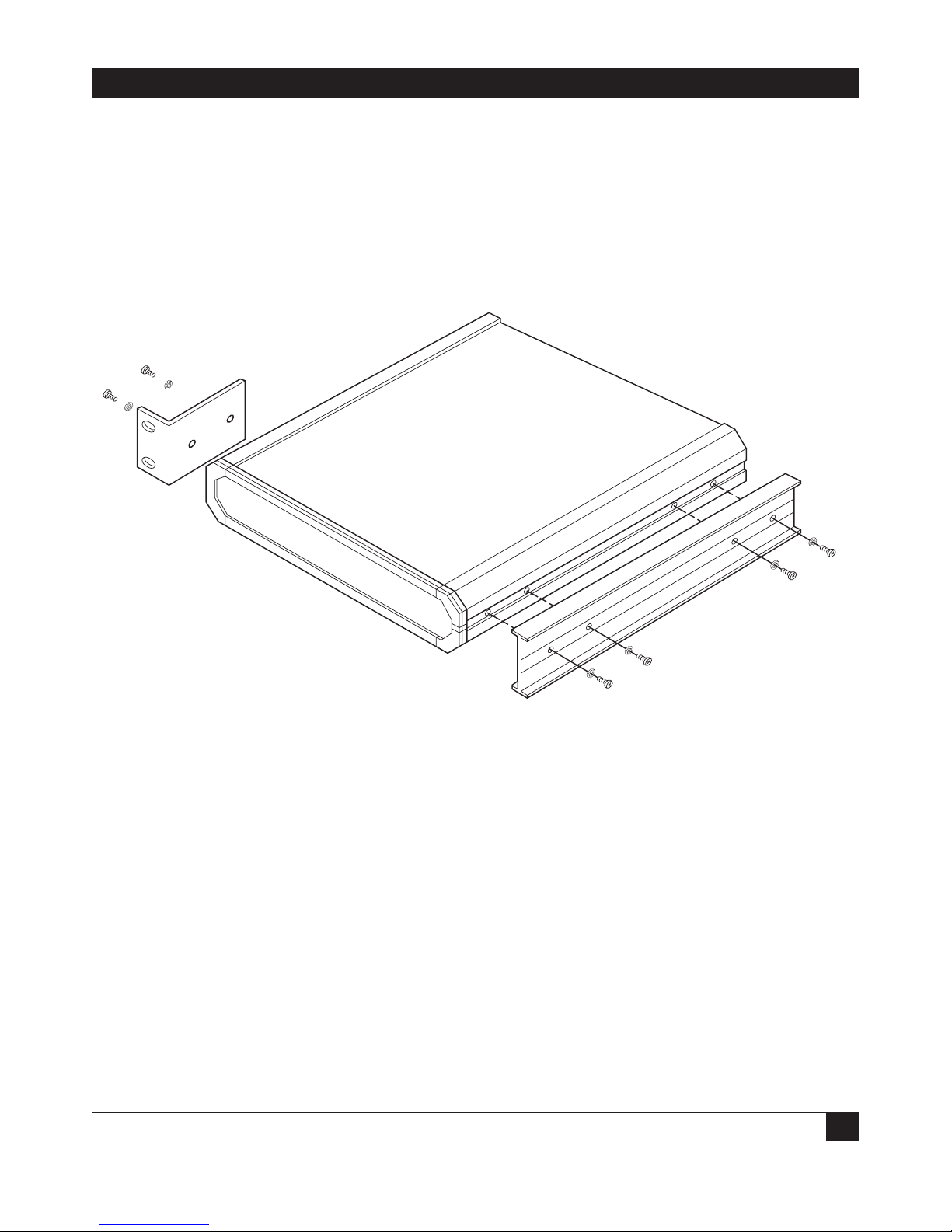
C.1 Rack Adapter Kit—Single-Unit Installation
The rack adapter components for single-unit installation include one short bracket and one long
bracket. The brackets are fastened by means of screws to the side walls of the case, as shown in the
illustration below. The short bracket attaches to the left side of the unit, and the long bracket to the
right side of the unit.
To prepare the unit for rack installation, attach the two brackets to the side walls of the unit. Each
bracket is fastened by means of two screws (with flatwashers), which are inserted into the two front holes
on the side wall (nuts are already in place, on the inner side of the wall.
APPENDIX C: Rack Adapter Installation Kits
25
After attaching the brackets, the unit is ready for installation in the 19-inch rack. Fasten the brackets to
the side rails of the 19-inch rack by means of four screws (not included in the kit).
C.2 Rack Adapter Kit—Dual-Unit Installation
The rack adapter components for two units include two long side rails (one for each unit) which slide
one within the other to fasten the two units together, and two short side brackets which fasten the two
units to the 19-inch rack. (See the illustration below.)
To install two units:
1) Attach a long side rail to each unit (right side for one unit, left side for the other unit) using the
four screws and flat washers supplied. The long side rails must be attached in opposing fashion,
the narrow flange of the first rail opposite the wide flange of the second rail.
2) Attach a short bracket to the other side of each unit using the four screws and flat washers
supplied.
3) Slide one unit side rail within the other, so as to fasten the two units together (see the illustration
on the next page).
4) Secure the plastic caps supplied to the ends of the joined rails, to prevent sliding of the units and
to protect the rail ends.
The assembled units can now be fastened to the side rails of the 19-inch rack, by means of four screws
(not included in the kit), to each side.

G.703 RATE AND INTERFACE CONVERTERS
26

1000 Park Drive • Lawrence, PA 15055-1018 • 724-746-5500 • Fax 724-746-0746
© Copyright 1997. Black Box Corporation. All rights reserved.
 Loading...