

Black Box IC714AE-449-R2, IC714A-48-530-R2, IC714AE-530-R2, IC714A-530-R2, IC714A-V35-R2 User Manual
...
CUSTOMER
SUPPORT
INFORMATION
Order toll-free in the U.S.: Call 877-877-BBOX (outside U.S. call 724-746-5500)
FREE technical support 24 hours a day, 7 days a week: Call 724-746-5500 or fax 724-746-0746
Mailing address: Black Box Corporation, 1000 Park Drive, Lawrence, PA 15055-1018
Web site: www.blackbox.com • E-mail: info@blackbox.com
MAY 1997
IC714A-449-R2 IC714AE-449-R2 IC714A-48-449-R2
IC714A-530-R2 IC714AE-530-R2 IC714A-48-530-R2
IC714A-V35-R2 IC714AE-V35-R2 IC714A-48-V35-R2
IC714A-X21-R2 IC714AE-X21-R2 IC714A-48-X21-R2
G.703 Codirectional Converter
G.703
↔V.35 CODIRECTIONAL
PWR
TD
RD
LOS
TEST
ERR
PATT
REM
ANA
DIG

1
FCC AND DOC/MDC RFI STATEMENTS
FEDERAL COMMUNICATIONS COMMISSION
AND
INDUSTRY CANADA
RADIO FREQUENCY INTERFERENCE STATEMENTS
This equipment generates, uses, and can radiate radio-frequency energy, and if not
installed and used properly, that is, in strict accordance with the manufacturer’s
instructions, may cause interference to radio communication. It has been tested
and found to comply with the limits for a Class A computing device in accordance
with the specifications in Subpart B of Part 15 of FCC rules, which are designed to
provide reasonable protection against such interference when the equipment is
operated in a commercial environment. Operation of this equipment in a
residential area is likely to cause interference, in which case the user at his own
expense will be required to take whatever measures may be necessary to correct
the interference.
Changes or modifications not expressly approved by the party responsible
for compliance could void the user’s authority to operate the equipment.
This digital apparatus does not exceed the Class A limits for radio noise emission from
digital apparatus set out in the Radio Interference Regulation of Industry Canada.
Le présent appareil numérique n’émet pas de bruits radioélectriques dépassant les limites
applicables aux appareils numériques de la classe A prescrites dans le Règlement sur le
brouillage radioélectrique publié par Industrie Canada.

2
G.703 CODIRECTIONAL CONVERTER
NORMAS OFICIALES MEXICANAS (NOM)
ELECTRICAL SAFETY STATEMENT
INSTRUCCIONES DE SEGURIDAD
1. Todas las instrucciones de seguridad y operación deberán ser leídas antes de
que el aparato eléctrico sea operado.
2. Las instrucciones de seguridad y operación deberán ser guardadas para
referencia futura.
3. Todas las advertencias en el aparato eléctrico y en sus instrucciones de
operación deben ser respetadas.
4. Todas las instrucciones de operación y uso deben ser seguidas.
5. El aparato eléctrico no deberá ser usado cerca del agua—por ejemplo, cerca
de la tina de baño, lavabo, sótano mojado o cerca de una alberca, etc..
6. El aparato eléctrico debe ser usado únicamente con carritos o pedestales que
sean recomendados por el fabricante.
7. El aparato eléctrico debe ser montado a la pared o al techo sólo como sea
recomendado por el fabricante.
8. Servicio—El usuario no debe intentar dar servicio al equipo eléctrico más allá
a lo descrito en las instrucciones de operación. Todo otro servicio deberá ser
referido a personal de servicio calificado.
9. El aparato eléctrico debe ser situado de tal manera que su posición no
interfiera su uso. La colocación del aparato eléctrico sobre una cama, sofá,
alfombra o superficie similar puede bloquea la ventilación, no se debe colocar
en libreros o gabinetes que impidan el flujo de aire por los orificios de
ventilación.
10. El equipo eléctrico deber ser situado fuera del alcance de fuentes de calor
como radiadores, registros de calor, estufas u otros aparatos (incluyendo
amplificadores) que producen calor.
11. El aparato eléctrico deberá ser connectado a una fuente de poder sólo del
tipo descrito en el instructivo de operación, o como se indique en el aparato.

3
NOM STATEMENT
12. Precaución debe ser tomada de tal manera que la tierra fisica y la polarización
del equipo no sea eliminada.
13. Los cables de la fuente de poder deben ser guiados de tal manera que no
sean pisados ni pellizcados por objetos colocados sobre o contra ellos,
poniendo particular atención a los contactos y receptáculos donde salen del
aparato.
14. El equipo eléctrico debe ser limpiado únicamente de acuerdo a las
recomendaciones del fabricante.
15. En caso de existir, una antena externa deberá ser localizada lejos de las lineas
de energia.
16. El cable de corriente deberá ser desconectado del cuando el equipo no sea
usado por un largo periodo de tiempo.
17. Cuidado debe ser tomado de tal manera que objectos liquidos no sean
derramados sobre la cubierta u orificios de ventilación.
18. Servicio por personal calificado deberá ser provisto cuando:
A: El cable de poder o el contacto ha sido dañado; u
B: Objectos han caído o líquido ha sido derramado dentro del aparato; o
C: El aparato ha sido expuesto a la lluvia; o
D: El aparato parece no operar normalmente o muestra un cambio en su
desempeño; o
E: El aparato ha sido tirado o su cubierta ha sido dañada.

4
G.703 CODIRECTIONAL CONVERTER
DISCLAIMERS
This manual contains information proprietary to the manufacturer. No part
of this publication may be reproduced in any form whatsoever without prior
written approval.
No representation or warranties for the fitness of these products for any
purpose other than those specifically mentioned in this manual are made
either by the manufacturer or its agents.
The manufacturer reserves the right to revise this publication and make
changes without obligation to notify any person of such revisions and
changes.
The manufacturer shall not be liable for any direct, indirect, special,
incidental, or consequential damages, whether based on contract, tort, or any
legal theory.
SAFETY WARNING
Always observe standard safety precautions while installing, operating, or
troubleshooting this product. To avoid the possibility of electrical shock,
disconnect the unit’s power cord from the power source before you remove
the unit’s cover.
TRADEMARKS USED IN THIS MANUAL
Any trademarks mentioned in this manual are acknowledged to be the property of the
trademark owners.

5
TABLE OF CONTENTS
Contents
Chapter Page
1. Specifications .............................................................................................. 7
1.1 G.703 Interface ...................................................................................... 7
1.2 Data-Communications Interface .......................................................... 7
1.3 Data-Communications Control Signals ............................................... 8
1.4 Other Physical Specifications ............................................................... 9
2. Introduction .............................................................................................. 11
2.1 Functional Description ....................................................................... 11
2.2 Timing Theory .................................................................................... 13
2.2.1 CCITT G.703 Signalling ............................................................ 13
2.2.2 G.703 Codirectional Timing ..................................................... 13
2.2.3 Tail-End Clocking ...................................................................... 17
2.2.4 G.703 Codirectional Rules ......................................................... 17
2.3 Rate-Conversion Rules ........................................................................ 19
2.4 Physical Description ............................................................................ 19
3. Installation .................................................................................................. 20
3.1 Unpacking ........................................................................................... 20
3.2 Site Requirements ............................................................................... 20
3.3 Setting Jumpers ................................................................................... 21
3.3.1 Overview ..................................................................................... 21
3.3.2 The Jumper-Setting Procedure ................................................. 23
3.4 Installation in 19-Inch Racks .............................................................. 23
3.4.1 Overview ..................................................................................... 23
3.4.2 Installing a Single Unit in a 19-Inch Rack ................................ 24
3.4.3 Installing Two Units in a 19-Inch Rack ..................................... 25
3.5 Connecting Power and Data Cables .................................................. 27
3.5.1 Power Connection ..................................................................... 28
3.5.2 G.703 LINE Connection ............................................................ 29
3.5.3 DTE Connection ........................................................................ 30
3.5.4 Async Secondary-Channel Connection .................................... 30

6
G.703 CODIRECTIONAL CONVERTER
Contents (continued)
Chapter Page
4. Operation ................................................................................................... 31
4.1 Front-Panel Controls and LEDs ......................................................... 31
4.2 Operating Instructions ....................................................................... 33
4.2.1 Turn-On Procedure ................................................................... 33
4.2.2 Activating Loops ......................................................................... 33
4.2.3 Turn-Off Procedure ................................................................... 33
4.3 Diagnostic Loops ................................................................................. 33
4.3.1 The Modem Self-Test ................................................................. 34
4.3.2 Local Analog Loopback ............................................................. 35
4.3.3 Remote Digital Loopback .......................................................... 36
4.3.4 Local Digital Loopback ............................................................. 37
4.4 Calling Black Box ................................................................................ 38
4.5 Shipping and Packaging ..................................................................... 39
Appendix: Pinouts ............................................................................................. 42

7
CHAPTER 1: Specifications
1. Specifications
1.1 G.703 Interface
Type — Codirectional 64-kbps
Line — 4-wire, 19- to 26-gauge
Range — Up to 800 meters (1⁄2 mile) over 24-gauge wire
Impedance — 120 ohms nominal
Balance — Greater than 45 dB (up to 256 kHz)
Greater than 35 dB (up to 384 kHz)
Return Loss — Less than 20 dB (up to 128 kHz)
Less than 14 dB (up to 384 kHz)
“Pulse” Amplitude — 1.0 V nominal
“Zero” Amplitude — 0 V ± 0.1 V max
Clock Frequency — 64 kHz
Frequency Tracking — ± 500 ppm
Connector — 5-screw terminal block
Jitter Performance — To G.823 requirements
1.2 Data Communications Interface
Type — Models with “-449” affix: EIA RS-530 adapted to
EIA RS-449 (ITU-TSS V.11/V.36/EIA RS-422/423);
Models with “-530” affix: EIA RS-530;
Models with “-V35” affix: ITU-TSS V.35;
Models with “-X21” affix: ITU-TSS X.21/V.11

8
G.703 CODIRECTIONAL CONVERTER
Data Rate — 64, 56, or 48 kbps, user-selectable
Spare Bandwidth — [at 56 or 48 kbps:] “1’s” density bit stuffing as per
ITU-TSS V.110; additional asynchronous channel
at 1200 bps; or transfer of RTS to DCD control
signal, end-to-end
Connector — Models with “-449” affix: DB25 female cabled to
DB37 female;
Models with “-530” affix: DB25 female;
Models with “-V35” affix: 34-pin M-block female;
Models with “-X21” affix: DB15 female
1.3 Data-Communications Control Signals
Functional — DCD, 64 kbps: ON when Rx pair contains required
violations, OFF when the Rx pair does not
contain required violations;
DCD, 48 or 56 kbps: When the Rx pair contains
the required violations, the DCD signal reflects
the state of the remote RTS; DCD is always OFF
when no violations are detected;
CTS output: ON after RTS ON, with delay; OFF
when RTS OFF, or during Loss of Signal
condition;
DSR output: ON (+V) when power is available
Clock Source — From G.703 Receive pair (LBT), from DCE (EXT),
or from internal source (INT), user-selectable;
If LBT, three sub-options are user-selectable:
Unit is DCE and RC and TC signals are outputs
from the unit to the local DTE (LBT-DTE);
RC signal is an output from the unit to the local
DTE, but TC signal is an input from a tailcircuit DCE (LBT-DCE); or
X.21 only: Unit is DTE and RC and TC signals
are both inputs to the unit from the local DCE
(LBT-DCE21)

9
CHAPTER 1: Specifications
1.4 Other Physical Specifications
Compliance — EMI/RFI: FCC Part 15 Class A, DOC Class/MDC
classe A
Safety: IEC 380
Standards — Diagnostics: ITU-TSS V.52 and V.54
Internal Memory — 32 bits of RAM divided into (2) independent 16-bit
buffers
User Controls — (4) Front-mounted pushbuttons: Local Digital
Loopback (DIG), Local Analog Loopback (ANA),
Remote Digital Loopback (REM), and Test
Pattern (PATT);
(5) Internal jumpers: Connect/disconnect grounds,
clock source, LBT clock-signal derivation, data
rate, and V.54 delay;
(1) Internal solder contact to connect grounds;
Loopback tests can also be triggered by interface
signals from local DTE
Diagnostics — Local digital loopback; local analog loopback (V.54
Loop 3); remote digital loopback (V.54 Loop 2);
511-bit V.52 BERT; all user-initiated and user-
terminated
Indicators — (6) Front-mounted LEDs: Power (PWR), Receive
Data (RD), Transmit Data (TD), Loss of Signal
(LOS), Test (TEST), and Error (ERR)
Power — IC714A models : Directly from outlet through
detachable 6-ft. (1.8-m) power cord (included):
Optimal
Input: 115 VAC, 60 Hz, 0.2 amps;
Input Ranges: 103.5 to 126.5 VAC, 47 to 63 Hz;
IC714AE models: Directly
from outlet through
detachable 6-ft. (1.8-m) power cord (included):
Optimal
Input: 230 VAC, 50 Hz, 0.1 amps;
Input Ranges: 207 to 253 VAC, 47 to 63 Hz;

10
G.703 CODIRECTIONAL CONVERTER
Power (cont’d) —
IC714A-48 models: –48 VDC directly from source
through detachable power cord (not included except
for output-jack components);
All models: Consumption: 25 watts
Fuse — IC714A models: 0.2-amp;
IC714AE models: 0.1-amp;
IC714A-48 models: 250 V, 200 ma
Isolation Voltage — 1500 VAC between G.703 interface and each of
these: data-communication interface, AC mains
(transformer primary), and frame ground;
also 1500 VAC betwen AC mains (transformer
primary) and each of these: data-communication
interface and frame ground
NOTE: This measurement was derived by testing for
one minute.
Maximum Altitude — 8000 ft. (2348.4 m)
Temperature
Tolerance — 32 to 122°F (0 to 50°C)
Humidity
Tolerance — Up to 95% noncondensing
Enclosure — High-impact plastic
Size — 1.8"H x 7.6"W x 9.6"D (4.6 x 19.3 x 24.3 cm), but the
unit’s pushbuttons protrude up to 0.3" (66 mm)
from the front panel and the connectors protrude
up to 0.8" (1.9 cm) from the rear panel
Weight — Net: 3.7 lb (1.7 kg); Shipping: 6 lb. (2.7 kg)

11
CHAPTER 2: Introduction
2. Introduction
2.1 Functional Description
The G.703 Codirectional Converter converts the ITU-TSS (CCITT) G.703
codirectional (line) interface to standard data-communication interfaces. The
Converter can perform two conversions:
• Electrical Conversion — from G.703 to ITU-TSS V.35,
V.36/V.11 (EIA RS-
449/422/423),
X.21/V.11, or EIA RS-530.
• Data-Rate Conversion — from 64 kbps to 48 or 56 kbps, when required.
The electrical and rate conversions enable you to connect DCE devices to
PCM transmission equipment.
Different models of the Converter have different interface connectors
depending on which data-commu-nication interface they support:
•
Models whose product codes in-
clude “-449” support EIA RS-422/
423/ITUTSS V.11 signaling on the EIA RS-449/ITU-TSS V.36 physical interface.
The interface connector mounted on these
units is an RS-530 DB25 (see
the
next paragraph); an included adapter cable patches these to a
37-pin
D-subminiature (“DB37”)
female interface connector.
• Models whose product codes include “-530” support the EIA RS-530
physical/electrical interface (with ITU-TSS V.11-compatible signal levels);
they have a 25-pin D-subminiature (“DB25”) female interface connector.
• Models whose product codes include “-V35” support the ITU-TSS V.35
physical/ electrical interface; they have a 34-pin M-block (“M/34”) female
interface connector.
• Models whose product codes include “-X21” support
ITU-TSS V.11 signaling on the ITU-TSS X.21 physical interface; they have
a 15-pin D-subminiature (“DB15”) female interface connector.
Operating full-duplex at a transmission rate of 64 kbps, the Converter has a
range of up to 800 meters (
1
⁄2 mile) from the PCM equipment. The unit’s
receive-timing source is the recovered clock from the CCITT G.703 receive
pair. You can set a jumper to select any one of these transmit-timing sources:
• Recovered clock from the received pair;
• External timing from the data-communication (DTE) interface; or
• Internal timing (used only for testing and diagnostics).
Two internal 16-bit buffers accommodate the difference in clocking phase.
12
G.703 CODIRECTIONAL CONVERTER
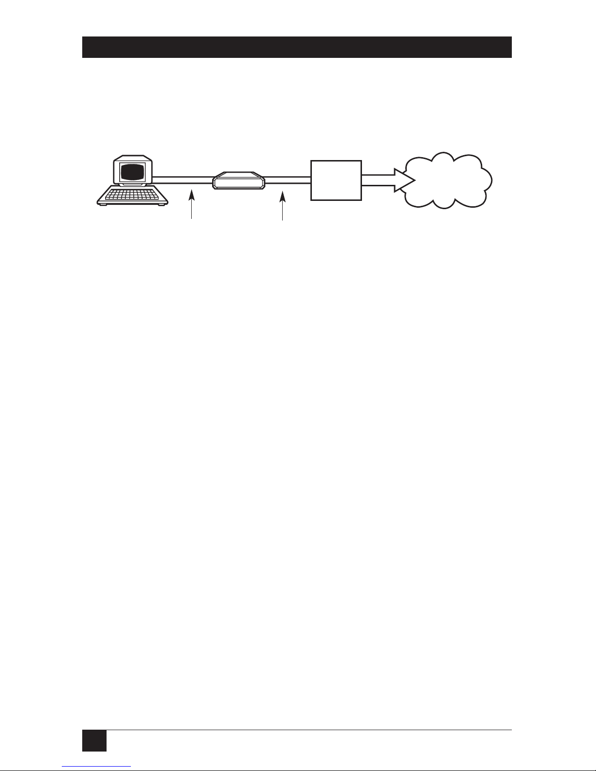
Figure 2-1 below shows a typical application of the G.703 Codirectional
Converter.
Figure 2-1. Typical G.703 Codirectional Converter application.
The Converter can act as a data-rate adapter, allowing you to connect DTEs
running at 48 or 56 kbps to a 64-kbps G.703-interface line. At 48 or 56 kbps,
depending on what you do or don’t connect to the Converters’ Request to
Send and Carrier Detect leads, you can use the extra bandwidth in any of
these ways:
• Nothing connected to Converter RTS (56 kbps only): To guarantee the
satisfaction of the “ones density” requirement, by placing a “1” after every
seven bits.
• Devices’ RTS connected to Converters’ RTS, and DCD to DCD: To pass a
control signal (RTS/DCD) end-to-end.
• Async devices’ Transmit Data to Converters’ RTS, and Receive Data to
CTS: As a 1200-bps asynchronous secondary channel for connecting
additional DTE units over the same link.
You can use the Converter’s front-panel LEDs to continuously monitor the
main channel’s activity and synchronization.
The Converter provides V.54 diagnostic capabilities with local digital and
analog and remote digital loopbacks. All three loops can be activated by
pressing front-panel pushbuttons; the latter two can be activated by raising
the appropriate interface signal from the local DTE.
Another of the front-panel pushbuttons triggers an internal 511-bit pseudorandom V.52 test pattern for direct end-to-end integrity testing. The ERR LED
flashes for each each error detected.
G.703
Codirectional
Converter
DTE
48, 56, or
64 kbps
T1 or E1
Network
V.35, V.36 (RS-449/422),
X.21, or RS-530 Cable
G.703 Codirectional
Line, 64 kbps
Office-
side PCM
equipment
13
CHAPTER 2: Introduction
2.2 Timing Theory
2.2.1 CCITT G.703 S
IGNALING
The CCITT G.703 codirectional signal is made up of two balanced signals:
The receive and transmit signals carry timing and data information.
The clock signal associated with each direction of transmission travels in the
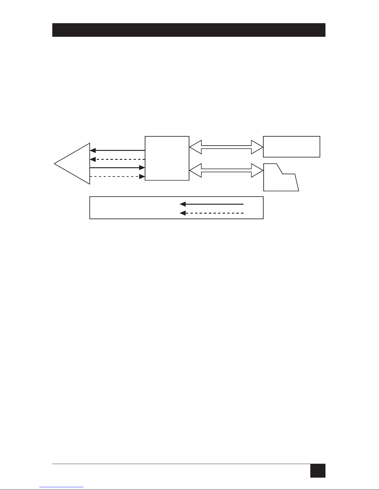
same direction as the data signal (see Figure 2-2 below).
Figure 2-2. G.703 Codirectional Converter signaling.
2.2.2 G.703 C
ODIRECTIONALTIMING
The G.703 Codirectional Converter can support virtually all timing options
that you might need, as described and illustrated in this section.
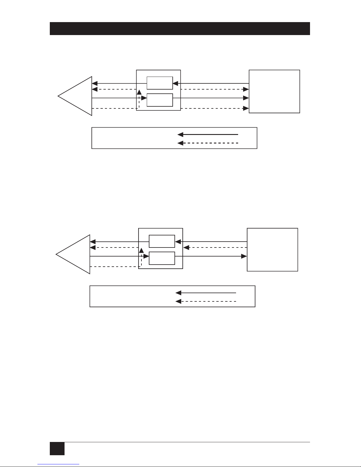
G.703 Receive Timing Used for G.703 Transmit Timing
When G.703 receive timing is used for G.703 transmit timing, three timing
options for the data-communication side, associated with the loopback timing
(LBT) on the G.703 side, are available:
• Receive Clock and Transmit Clock are both outputs from the Converter,
which serves as a DCE (see Figure 2-3 on the next page).
• X.21 interface only: Receive Clock and Transmit Clock are both inputs to
the Converter, which serves as a DTE (see Figure 2-4 on the next page).
• Receive Clock is an output from the Converter, while Transmit Clock is an
input to the Converter from an external DCE, for connection to a tail
circuit (see Figure 2-5 on page 15).
Information Signal
Timing Signal
PCM
Equip.
DCE
(Modem, Mux, etc.)
async (PC,
Term., etc.)
DTE,
G.703
Codirectional
Converter
14
G.703 CODIRECTIONAL CONVERTER
Figure 2-3. LBT-DTE Connection.
Figure 2-4. LBT-DCE21 Connection.
Information Signal
Timing Signal
Information Signal
Timing Signal
G.703 Codirectional
Converter
Elastic
Buffer
Elastic
Buffer
DCE
PCM
Equip.
Elastic
Buffer
Elastic
Buffer
G.703 Codirectional
Converter
DCE
PCM
Equip.

15
CHAPTER 2: Introduction
Figure 2-5. LBT-DCE Connection.
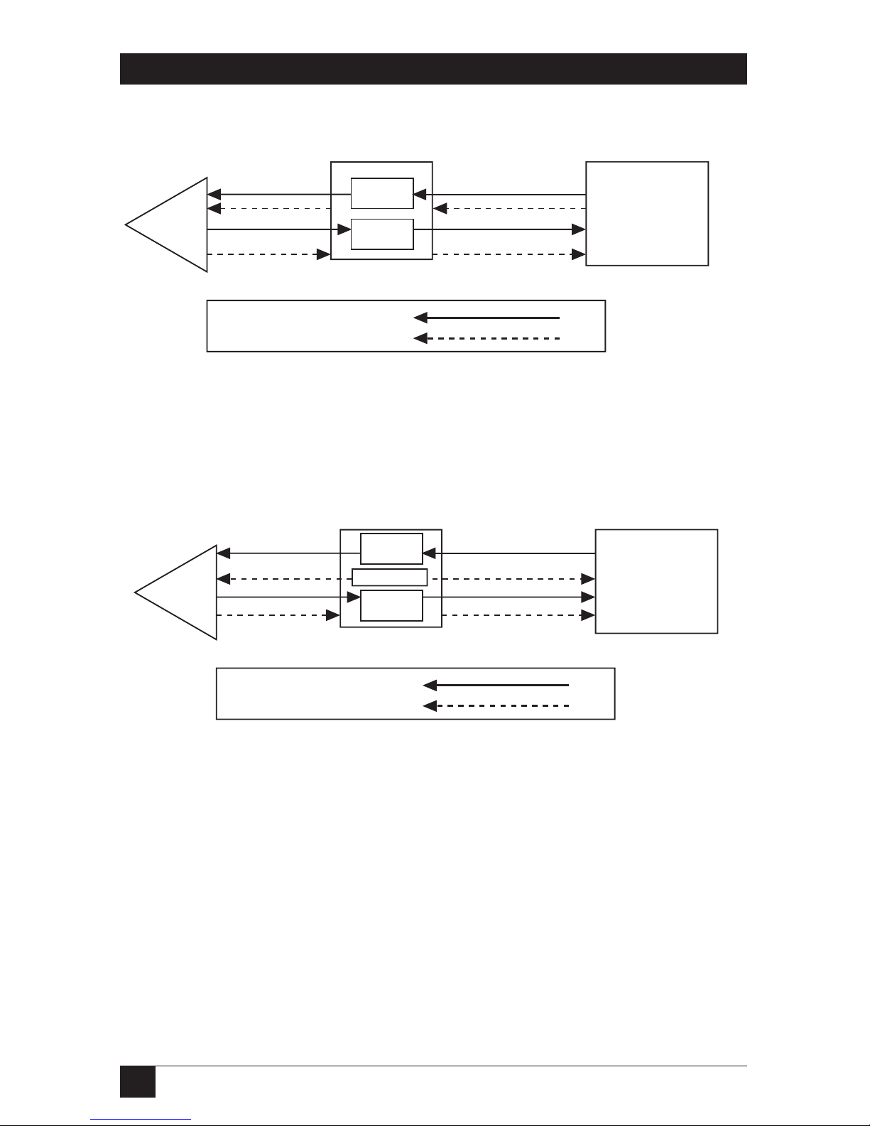
Transmit-Clock Timing Mode
When you use the external transmit clock on the data-communications side
for G.703 transmit timing, there is complete independence, within the G.703
Codirectional Converter, between the receive and the transmit directions of
transmission. Figure 2-6 on the next page shows this timing mode.
Internal-Clock Timing Mode
The Converter’s internal oscillator is usually used as the source for G.703
transmit timing for testing purposes only, but can also be used with systems
that do not have a clock source. Figure 2-7 on the next page shows this timing
mode.
Information Signal
Timing Signal
Elastic
Buffer
Elastic
Buffer
G.703 Codirectional
Converter
DCE
PCM
Equip.
16
G.703 CODIRECTIONAL CONVERTER
Figure 2-6. Transmit-Clock Timing Mode.
Figure 2-7. Internal-Clock Timing Mode.
Information Signal
Timing Signal
Information Signal
Timing Signal
DCE
G.703 Codirectional
Converter
PCM
Equip.
Elastic
Buffer
Elastic
Buffer
G.703 Codirectional
Converter
DTE or DCE
PCM
Equip.
Elastic
Buffer
Elastic
Buffer
Oscillator

17
CHAPTER 2: Introduction
2.2.3 T
AIL
-ENDC
LOCKING
Transmit clock from the external DCE source is provided for applications
requiring the use of a modem in order to reach a remote DTE, as shown in
Figure 2-8 on the next page (see Figures A-2, A-7, and A-10 in the Appendix
for pinouts). Use the LBT-DCE-timing mode with the G.703 Codirectional
Converter (see Figure 2-5 on page 15).
2.2.4 G.703 C
ODIRECTIONALRULES
G.703 codirectional signals, in each direction of transmission, are coded as
follows: The composite timing/ data signal conveys the 64-KHz bit-timing
information, the 8-KHz octet information (by introducing violations into the
signal), and the 64-kbps data pattern.
• A binary one (64-kbps bit period) is coded as a block of the four bits
“1100.”
• A binary zero (64-kbps bit period) is coded as a block of the four bits
“1010.”
The binary signal is converted into a three-level signal by alternating the
polarity of the blocks. The alternation of the polarity of the blocks is violated
every eight blocks (see Figure 2-9 on the next page).

18
G.703 CODIRECTIONAL CONVERTER
Figure 2-8. Tail-Circuit Application.
Figure 2-9. G.703 Code Conversion.
6 7 8 1 2 3 4 5 6 7 8 1
0 0 0 1 1 0 1 0 1 1 1 0
G.703 Codirectional
Converter
G.703 Line
Tail-End Circuit
TC
TD
RD
RC
TD
EXTC
EXTC
RD
RC
Modem
(V.35, V.36, RS-530)
Modem
Line Side of
Office
Terminal
Bit Number
64-kbps data
Binary Data
Three-Level Data
Violated Data

19
CHAPTER 2: Introduction
2.3 Rate-Conversion Rules
56-to-64-kbps conversion is performed by suppressing bit position number 8.
This bit position coincides with the introduced violation (as shown in Figure
2-9), and thus suppressing it conforms to the requirements of ITU-TSS
(CCITT) standard V.110 for 56- to 64-kbps rate conversion. The suppressed
bit can be used for RTS-DCD end-to-end signalling or for a secondary async
channel. North American T1 (1.544-Mbps) applications require that this bit
position be set to a binary “1.” You can do this easily by leaving the RTS pin
open (not connected).
48-to-64-kbps conversion is performed by suppressing bit positions number 7
and 8. The suppressed bits are used in the same way as those suppressed for
56-to-64-kbps conversion.
2.4 Physical Description
The G.703 Codirectional Converter is a standalone unit. The unit is designed
for installation on top of a bench or a shelf, but can also be mounted on a 19inch rack with the proper adapter kit. One or two standalone units can be
installed together.

20
G.703 CODIRECTIONAL CONVERTER
3. Installation
This chapter shows you how to install the G.703 Codirectional Converter.
After you complete the installation, refer to Chapter 4 for operating
information.
The AC-powered (IC714A and IC714AE) models of the G.703 Codirectional
Converter are designed for placement on a shelf or bench, and come
completely assembled. With a rackmount-adapter kit (not included—call for a
quote), you can also install them in a 19-inch rack.
The DC-powered (IC714A-48) model of the G.703 Codirectional Converter is
designed to operate from –48 VDC. With a rackmount adapter kit, these can
also be installed in a 19-inch rack.
3.1 Unpacking
Unpack the equipment this way:
• Carefully take the G.703 Codirectional Converter out of the box it came
in and place the Converter on a clean surface.
• Inspect the unit for damage. Immediately report any damage you find to
your carrier and to Black Box.
3.2 Site Requirements
An AC-powered G.703 Codirectional Converter should be installed within 5
feet (1.5 m) of a grounded AC outlet capable of providing 230 or 115 volts.
It must be situated within half a mile (800 m) of the PCM equipment.
A DC-powered G.703 Codirectional Converter should be installed near a
grounded DC power source capable of providing –48 volts. It must be situated
within half a mile (800 m) of the PCM equipment.
Make sure that there is at least 4 inches (10 cm) of clearance behind the
G.703 Codirectional Converter for signal lines and interface cables.

21
CHAPTER 3: Installation
3.3 Setting Jumpers
3.3.1 O
VERVIEW
Prior to installing the G.703 Codirectional Converter, determine its
configuration in the data system and set its jumpers accordingly. Refer to
Table 3-1 on page 22. The diagrams in Chapter 2 can help you identify the
required jumper selection. Jumper locations on the printed circuit board are
shown in Figure 3-1 on the next page. Read the instructions in Section 3.3.2
before making any changes.
Figure 3-1. Board layout of the G.703 Codirectional Converter.
NOTES
Be aware that in the drawing above, the jumpers are exaggerated in size
and other elements are minimized or deleted. For example, the JP1
jumper is in fact partially obscured by the interface module in the ACpowered models. Also, in both AC- and DC-powered models, the “JP1”
label is partially or completely covered by material that helps secure the
board to the rear panel.
There is also a second element labeled “JP1” on the interface module
itself. Just like the other JP1, this element will also serve to connect
chassis ground to signal ground, but it isn’t a jumper. Rather, it is two
contact points that can be soldered together to form a permanent
connection. Be very certain that you will always want the grounds tied
common before you solder these points together.
LD1
LD2
LD3
LD4
LD5
LD6
SW4
SW3
SW2
SW1
JP1
AC
OUTLET
OFF
CHASS
INTERFACE
MODULE
ON
V.54 DLY
JP2
48K
BAUD RATE
56K
64K
JP7
CONNECT
DISCONN
TC G.703 CONNECT TO
JP6
JP5
LBT
EXE
INT
DCE21
DCE
DTE
22
G.703 CODIRECTIONAL CONVERTER
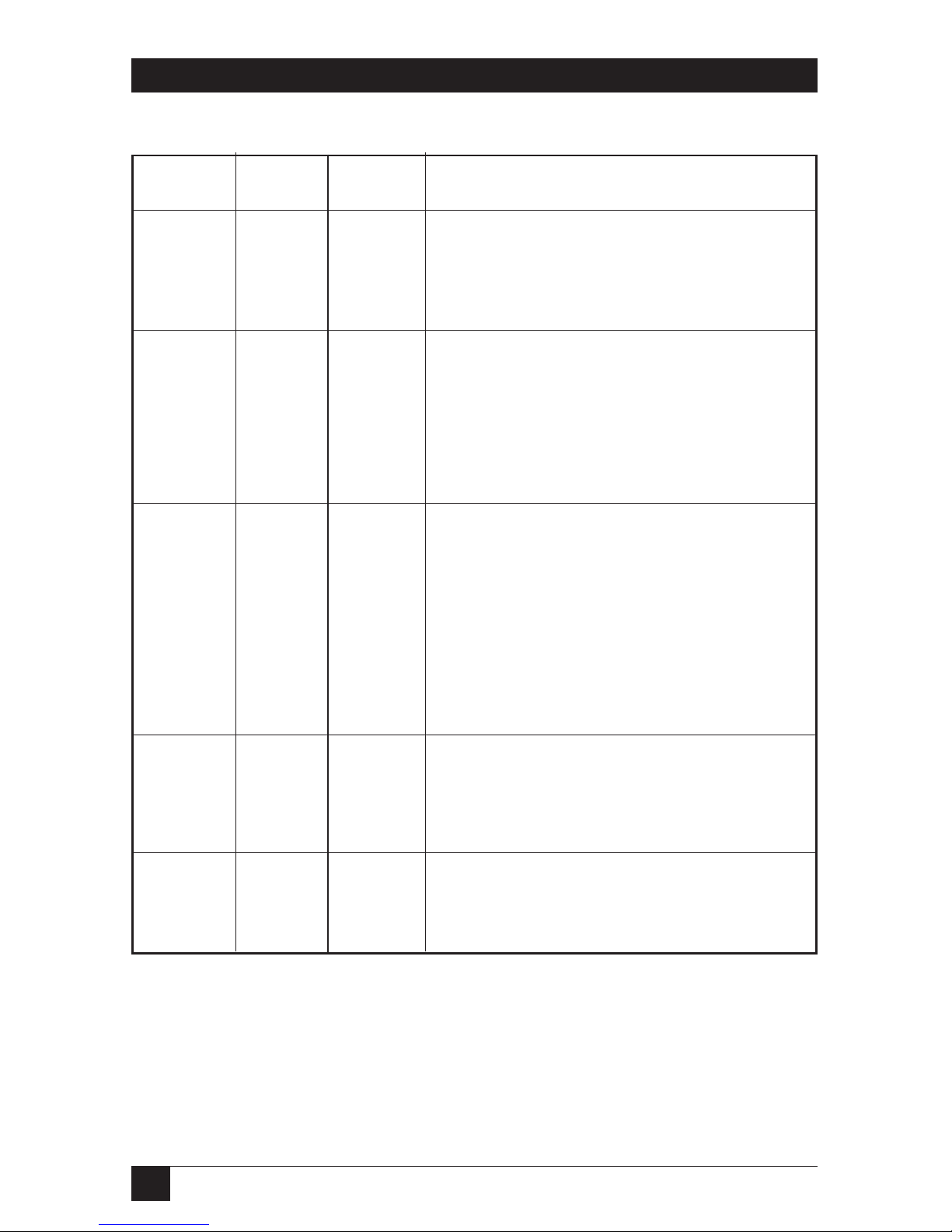
Table 3-1. Setting Jumpers
Jumper Factory Possible
Identity Setting Position Function
GND Connect Connect: Protective ground connected to
signal ground.
Disconn Disconn Disconn: Protective ground disconnected
from signal ground.
TC G.703 LBT LBT The Tx-pair timing is the recovered clock
from the CCITT G.703 Rx pair.
EXT The Tx-pair and transmit timing are from
the RS-422/V.35 external source.
INT The Tx-pair and transmit timing are from
the internal source.
LBT DTE DTE Connection to DTE, with transmit and
receive timing derived from the unit’s
recovered clock.
DCE Connection to DCE, while both the DCE
and the unit operate with external
transmit timing.
DCE 21 Connection to X.21 DCE. The unit’s
transmit and receive timing are derived
from the DCE.
BAUD 64 64 Data rate is 64 kbps.
RATE
56 Data rate is 56 kbps.
48 Data rate is 48 kbps.
V.54 DLY ON ON V.54 delay is active, preventing mutiple
loopback on tail-end circuits.
OFF V.54 delay is not active.

23
CHAPTER 3: Installation
3.3.2 T
HE
J
UMPER-SETTINGPROCEDURE
CAUTION!
Disconnect the unit from the power line before removing it from its
housing.
WARNING: HIGH VOLTAGE!
Any adjustment, mainten-ance, and repair of the open instrument under
voltage should be avoided as much as possible, and, when inevitable,
should be carried out only by a skilled person who is aware of the hazard
involved. Capacitors inside the instrument may still be charged even
after the instrument has been dis-connected from the power source.
To change the settings of any jumpers, perform the following steps:
• Disconnect the AC power cord from the AC mains outlet.
• Unscrew the two rear-panel screws until the rear panel becomes loose.
This releases the unit’s “drawer” mechanism; now you can pull the screws
as if they were the knobs on a drawer and expose or remove the unit’s
circuit board.
• Identify the jumpers(s) (refer to Figure 3-1 on page 21).
• Move the jumper(s) to your desired position(s).
• Replace the circuit board and screw the rear-panel screws back in.
3.4 Installation in 19-inch Racks
3.4.1 O
VERVIEW
The G.703 Codirectional Converter can be installed in 19-inch racks. It is 1U
(1.75", 4.4 cm) high and is slightly less than half as wide as the available
mounting area. Two rack-adapter kits are available: One kit provides the
hardware necessary to install a single unit, and the other provides the
hardware necessary to install two units side by side. Sections 3.4.2 and 3.4.3
provide step-by-step instructions for installation of single or dual units.
CAUTION!
Disconnect the units from AC power while performing the following
procedures.
24
NAME
3.4.2 I
NSTALLING A
S
INGLEUNIT IN A
19-
INCHRACK
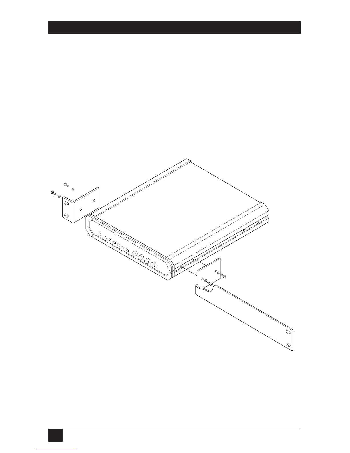
The rack-adapter kit for single-unit installation includes one short bracket
and one long bracket. The brackets are fastened with screws to the two side
walls of the case, as shown in Figure 3-2 below.
To prepare the Converter for rack installation, attach the two brackets to the
sides of the unit. Do this by inserting screws and flat washers into the two
holes at the front of each side of the Converter (nuts are already in place
inside the unit).
After attaching the brackets, install the unit in your 19-inch rack by fastening
the brackets to the rack’s side rails with four screws (not included in the kit),
two on each side.
Figure 3-2. Installing a single unit in a 19-inch rack.

25
CHAPTER
3.4.3 I
NSTALLING
TWOU
NITS IN A
19-I
NCHRACK
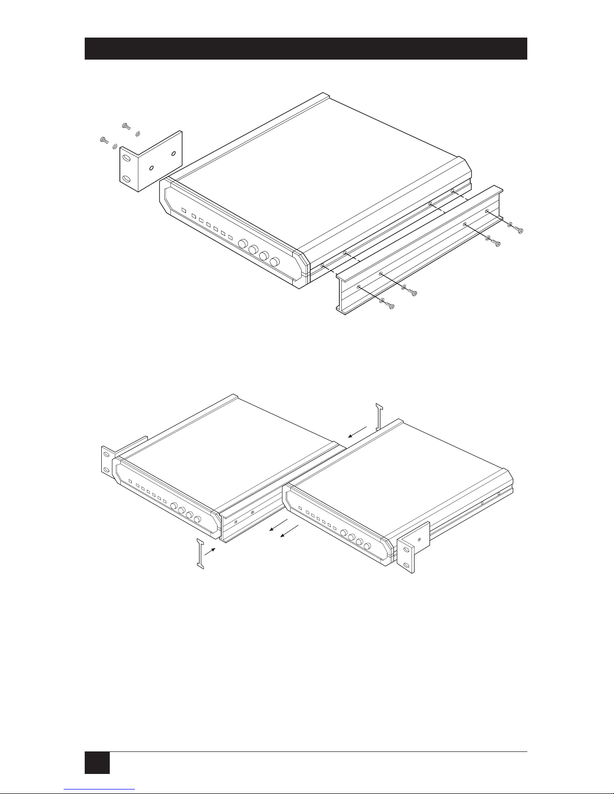
The adapter kit includes two long side rails (one for each unit), which slide
into each other to fasten the units together, and two short side brackets,
which hold the two Converters side by side in a 19-inch rack. Refer to Figure
3-3 on the next page when you perform the following procedure:
1. Fasten one long side rail to each Converter—one rail on the right side of
one unit, the other rail on the left side of the other unit—using the four
included screws and flat washers. The rails must be attached so that they
“oppose” each other: The narrow flange of the first rail must face the
wide flange of the second rail.
2. Using four included screws and flatwashers for each bracket, attach the
two short brackets to the vacant sides of the Converters.
3. Slide the two Converters’ side rails into each other, fastening the two
units together.
4. Secure the included plastic caps to the ends of the rails, to protect the
rail ends and prevent the units from moving.
5. You can now use four screws (not supplied with the kit), two on each
side, to fasten the assembled units to the side rails of the 19-inch rack.
26
G.703 CODIRECTIONAL CONVERTER
Figure 3-3. Installing two units in a 19-inch rack.

27
CHAPTER 3: Installation
3.5 Connecting Power and Data Cables
After you set the G.703 Codirectional
Converter’s internal jumpers, the
Converter is ready to be cabled for operation.
Its electrical connectors are located on its rear panel, as shown in Figures 3-4
and 3-5 below. These consist of a female interface connector labeled “DTE,” a
5-screw terminal block,” and a 3-prong AC or DC inlet. (The AC inlet also
contains an integral fuse compartment.)
The interface connector (M/34, DB15, DB25, or DB25 cabled to DB37)
carries input/output data, clock signals, and control signals
between the
Converter and the DCE
(for more detailed information, refer to the
Appendix).
The terminal block has five screws for connecting transmit and receive ITUTSS (CCITT) G.703 lines—the transmit pair where XMT is indicated (for
data output from the unit), the receive pair where RCV is indicated (for data
input to the unit), and chassis ground where GND is indicated.
Connect power and data cables to the Converter as described in the following
subsections.
Figure 3-4. Rear panel of the 115-VAC (IC714A-530-R2) and 230-VAC
(IC714AE-530-R2) RS-530 models of the Converter.
Figure 3-5. Rear panel of the –48-VDC RS-530 model of the
G.703 Codirectional Converter (IC714A-48-530-R2).
DTE
XMT RCV GND
48V
CHASS
GND
+-
DTE
XMT RCV GND
115 VAC / - 0.2A T 250V

28
G.703 CODIRECTIONAL CONVERTER
3.5.1 P
OWER
C
ONNECTION
The power connection provides AC or DC voltage to the Converter.
To make this connection on the 115-VAC (IC714A) models, first attach the
IEC 320 female outlet of the included power cord to the IEC 320 male inlet
on the Converter’s rear panel.
To make this connection on the 230-VAC (IC714AE) models, first attach the
IEC 320 female outlet of an appropriate power cord to the IEC 320 male inlet
on the Converter’s rear panel. (This power cord must have a plug on the
other end that will fit the site’s mains outlets.)
WARNING!
AC-POWERED MODELS: BEFORE PLUGGING THIS UNIT INTO AN
OUTLET OR
OTHER LIVE POWER SOURCE,
make sure its protective earth
contact is connected to the protective conductor of the (mains) power
cord. The mains plug must be inserted only in a socket outlet provided
with a protective earth contact. The protective action must not be
negated by use of an extension cord (power cable) without a protective
(grounding) conductor.
If the Converter’s fuse blows (opens), make sure that you replace it only
with a fuse rated for the required amount of current. You must avoid
using repaired fuses or short-circuiting the fuse holders. The fuse, and
one replacement fuse, are located in the top part of the mains connector
on the Converter’s rear panel. The nominal current value of the fuse is
0.125 A for 230-VAC operation or 0.25 A for 115-VAC operation.
Whenever it is likely that the protection offered by the fuse has been
impaired, the unit must be made inoperative and secured against any
unintended operation.
To make this connection on the –48-VDC (IC714A-48) models, first attach the
3-pin DIN jack of an appropriate power cord to the 3-pin DIN plug on the
Converter’s rear panel. (Though an entire cord isn’t included, we do include
the components you’ll need to assemble a 3-pin DIN jack that you can attach
to a cord you build. For more information, consult standard reference works
on cable assembly.)
After you have attached the power cord and have made sure that the cord is
properly grounded, you can plug the power cord into a working mains outlet
(AC models) or DC source (DC model).
CAUTION!
The unit has no power switch. It starts operating as soon as power of the
proper type is applied to its POWER connector.

29
CHAPTER 3: Installation
3.5.2 G.703 LINE C
ONNECTION
The G.703 LINE connection provides an interface for the TX and RX signals
between the Converter and G.703 line equipment. To make this connection,
attach the wires from the line equipment to the terminal block on the
Converter this way:
NOTE
There is no + or - XMT or RCV. The unit is auto-detecting and nonpolarity sensitive.
• XMT (line equipment) to RCV (Converter);
• XMT (line equipment) to RCV (Converter);
• RCV (line equipment) to XMT (Converter);
• RCV (line equipment) to XMT (Converter);
• Optional: Ground (line equipment) to ground (Converter—the
rightmost terminal).
Figure 3-6. Wire-insertion details.
XMT RCV GND
1) Insert screwdriver into square hole.
2) Raise inserted screwdriver, putting
pressure on
ramp inside square hole.
Wire clamp in round hole
will open.
3) Insert stripped end of wire and remove screwdriver.

30
G.703 CODIRECTIONAL CONVERTER
3.5.3 DTE C
ONNECTION
The interface (DTE) connector pro-vides an interface for input/ output data,
as well as clock and control signals, between the Converter and a DTE or
DCE. For the most part, the different models have the type of connector
appropriate for their designated interface: V.35 models
have an M/34 female;
RS-530 models
have a DB25 female; and X.21 models have a DB15 female. On
V.36/RS-449 models, the connector on the Converter is actually an RS-530
DB25 female, but you can attach the included adapter cable to patch this
connector to a standard DB37 female. The pinouts of these connectors, of the
RS-530-to-RS-449 adapter cable, and of cables you can run to DTE and DCEs,
are listed in the Appendix.
To connect the Converter to a DTE or DCE, use an appropriate cable that is
pinned correctly (straight-through for DTE, crossed for DCE—consult the
Appendix). Run this cable from the other device to the Converter and attach
it to the Converter’s interface connector (or, on the V.36/RS-449 model, to
the adapter cable’s DB37 connector).
3.5.4 A
SYNCSECONDARY
-C
HANNELCONNECTION
Non-X.21 models of the G.703 Codirectional Converter can support a 1200bps async secondary channel when your main channel is operating at 56 or 48
kbps, but special T-cables are required. Call Black Box Technical Support for
more information.

31
CHAPTER 4: Operation and Troubleshooting
4. Operation and Troubleshooting
Besides giving operating instructions, this chapter describes the front-panel
controls and LEDs and their functions, and tells you what to do if there is a
problem with the unit.
4.1 Front-Panel Controls and LEDs
Six LEDs are visible through the front panel (see Figure 4-1 below). Each
LED’s function is described in Table 4-1 on the next page.
Four pushbuttons are available for activating diagnostic tests, as described in
Table 4-1.
Figure 4-1. Front panel of the G.703 Codirectional Converter.
PWR
DIG ANA REM PATT
TD RD LOS TEST ERR

32
G.703 CODIRECTIONAL CONVERTER
Table 4-1. Functions of LEDs and Controls.
Indicator/Control Function
PWR (Green LED) Lights when the unit is receiving power.
Power
TD (Yellow LED) Flickers when data is present at transmit
Transmit Data input and goes off when a steady mark is
present.
RD (Yellow LED) Flickers when data is present at receive
Receive Data output and goes off when a steady mark is
present.
LOS (Red LED) Lights when the RX pair does not contain
Loss of Signal the violations required.
TEST (Red LED) Lights when a loopback is performed.
Test
ERR (Red LED) Lights when errors are detected in the test
pattern. Active only after PATT button is
pressed.
DIG (Pushbutton) Activates local digital loopback.
ANA (Pushbutton) Activates local analog loopback.
REM (Pushbutton) Activates remote digital loopback.
PATT (Pushbutton) Activates V.52-compliant pattern test.

33
CHAPTER 4: Operation and Troubleshooting
4.2 Operating Instructions
The G.703 Codirectional Converter operates unattended once it has been
installed and powered up. Intervention is only required when the Converter is
set up for the first time, when it must be adapted to new operational
requirements, or when diagnostic loops are necessary.
4.2.1 T
URN-ONPROCEDURE
The Converter is turned on as soon as power is connected. When power is
connected, the PWR LED comes on and remains lit as long as the unit
receives power.
If the LOS LED is ON, check the line and make sure it is connected properly.
The TEST LED is ON while any front-panel pushbutton is depressed, or when
one of the loopback pins of the interface (DTE) connector is active.
4.2.2 A
CTIVATINGLOOPS
When performing tests, remember:
• Activation of a test loop interrupts normal traffic flow.
• Only one test may be activated at a time.
4.2.3 T
URN-OFFPROCEDURE
The Converter can be turned off only by disconnecting its power.
NOTE
Always disconnect the power cord from the AC outlet before you
disconnect it from the Converter.
4.3 Diagnostics
The G.703 Codirectional Converter provides local loopback and remote
digital loopback in compliance with the V.54 standard. These loopbacks can
be activated manually from the unit’s front panel. On any of the datacommunications (DTE) interfaces that the Converter supports except X.21,
these loopbacks can also be activated electronically through the DTE
connection. (X.21 was developed before V.54 and does not include provisions
for electronic loopback control.)
The loop test buttons (DIG, ANA, and REM) and LEDs built into the
Converter allow you to rapidly check the unit, the attached cables, and the
attached DTEs. Use the test procedures described in this section to verify
normal system operation and to isolate faulty equipment if a failure occurs.
(Before testing the operation of the system equipment and line circuits, make
sure that all devices are turned on and are properly configured.)

34
G.703 CODIRECTIONAL CONVERTER
The Converter is also capable of operating opposite any 511 BERT tester.
When you use one Converter opposite another, either with one or both PATT
buttons depressed (see Figure 4-2 below) or with an external BERT
transmitting the same V.52 (511-bit) pattern, you can test the complete link.
To activate the BERT, depress the PATT button. The ERR LED will light
momentarily, just to confirm that the LED is working, and then the test will
proceed. If errors are detected, the ERR LED will be continuously lit (if the
errors are continuous) or will blink (for intermittent errors).
NOTE
While PATT is depressed, the data-communications interface is
functionally disconnected.
4.3.1 T
HE
M
ODEMSELF-TEST
To verify that the G.703 Codirectional Converter itself is operating correctly,
initiate the modem self-test by depressing the PATT and ANA buttons (refer
to Figure 4-3 on the next page):
1. Press ANA to start local analog loopback. The TEST LED should light.
2.
Press PATT to begin test-pattern
transmission. Verify that the TEST LED
is still lit and that the ERR LED lights briefly.
3. If the ERR stays lit or continues to flicker after the initial flash, the
Converter is faulty; call Black Box to arrange for repair or replacement.
Otherwise, the Converter passes the test; restore all of the buttons to
their normal positions.
Figure 4-2. Two Converters doing end-to-end BERT.
PATTERN
GENERATOR
PATTERN
TESTER
ERROR
PATT
DEPRESSED
PATTERN
GENERATOR
ERROR
PATT
DEPRESSED
(DISCONNECTS
EXTERNAL DTE)
PATTERN
TESTER
RCV
DTE
XMT

35
CHAPTER 4: Operation and Troubleshooting
Figure 4-3. Modem self-test.
4.3.2 L
OCALANALOGLOOPBACK
Activate the local analog loopback test by depressing the ANA button or by
raising the level of the Local Loopback signal received by the Converter’s
DTE-side connector (on DB25 Pin 18 on the RS-530 models, M/34 Pin JJ
on the V.35 models, or DB37 Pin 10 on the V.36/RS-449 models). This test
checks the performance of the local Converter’s modem, the local DTE,
and the connections between them. Perform this test separately at the
local and remote sites (refer to Figure 4-4 below):
1. Press ANA or raise Local Loopback to start local analog
loopback. The
TEST LED should
light. The Converter’s G.703 transmit output should
be connected to its own receiver.
Figure 4-4. Local analog loopback.
ANA
DEPRESSED
DTE
XMTR
RCVR
LINE
DATA
CLK
CLK
DATA
PATTERN
GENERATOR
PATTERN
TESTER
ERROR
PATT
DEPRESSED
ANA
DEPRESSED
XMTR
RCVR

36
G.703 CODIRECTIONAL CONVERTER
2. Verify that the DTE is operating properly and can be used for a test.
3. Perform the test using one of these methods:
• Send data from the DTE and check the echoed data stream.
• Hook up an external Bit Error Rate Test (BERT) unit in place
of the DTE.
• Use the Converter’s internal BERT. Press the PATT button.The ERR
LED should light briefly just to confirm that the LED is working, and
then the test will proceed. If errors are detected, the ERR LED will
be continuously lit (if the errors are continuous) or will blink
(for intermittent errors).
4. Repeat Steps 1 through 3 at the remote site.
5. If the BERT tests show no errors, but the data echoed back to either
DTE is bad, check the DTE and the cable connecting it to the
Converter—one of them is faulty.
6. After the test is complete or the fault has been corrected, restore the ANA
button to its normal position. Proceed with the digital loopback tests.
4.3.3 R
EMOTEDIGITAL
L
OOPBACK
Activate the remote digital loopback test by depressing the REM button or by
raising the level of the Remote Loopback signal received by the Converter’s
DTE-side connector (on DB25 Pin 21 on the RS-530 models, M/34 Pin HH
on the V.35 models, or DB37 Pin 14 on the V.36/RS-449 models). This test
involves creating an outbound loopback at the remote Converter (see Figure
4-5 on the next page). The test checks the performance of the local and
remote Converters and the lines between them:
1. Press REM or raise Remote Loopback; the local Converter
will signal the
remote unit to start
remote digital loopback. The TEST LED should light
on both units. The remote Converter’s G.703 receive input should be
connected to its own transmitter.
2. Perform a Bit Error Rate Test (BERT). Either:
• Hook up an external Bit Error Rate Test (BERT) unit in place of the
local DTE; or
• Use the local Converter’s internal BERT. Press the PATT button. The
ERR LED should light briefly just to confirm that the LED is working,
and then the test will proceed. If errors are detected, the ERR LED
will be continuously lit (if the errors are continuous) or will blink
(for intermittent errors).

37
CHAPTER 4: Operation and Troubleshooting
Figure 4-4. Remote digital loopback.
3. If the BERT test indicates a fault, but both Converters pass their modem
self-tests (see Section 4.3.1), there is a problem somewhere in the
communication line between the units.
4. After the test is complete or the fault has been corrected, restore the
REM button to its normal position. Proceed with local digital loopback.
4.3.4 L
OCALDIGITALLOOPBACK
Activate the local digital loopback test by depressing the DIG button on the
Converter’s front panel. This test involves creating an outbound loopback at
the local Converter (see Figure 4-5 on the next page). It works the same way
as if the remote operator had initiated a remote digital loopback at the
remote site. With this test, the remote operator can check the performance of
the remote and local Converters and the lines between them:
1. Press DIG; the local Converter will signal the remote unit and will start
local digital loopback. The TEST LED should light on both units. The
local Converter’s G.703 receive input should be connected to its own
transmitter.
2. Perform a Bit Error Rate Test (BERT). Either:
• Hook up an external BERT unit in place of the remote DTE; or
• Use the remote Converter’s internal BERT. Press the PATT button.
The ERR LED should light briefly just to confirm that the LED is
working, and then the test will proceed. If errors are detected, the ERR
LED will be continuously lit (if the errors are continuous) or will blink
(for intermittent errors).
REM
DEPRESSED
DATA
CLK
RCVR
CLK
DATA
XMTR
LOCAL
DTE
XMTR
RCVR
REMOTE
DTE

38
G.703 CODIRECTIONAL CONVERTER
Figure 4-5. Local digital loopback.
3. If the BERT test indicates a fault, but both Converters pass their modem
self-tests (see Section 4.3.1), there is a problem somewhere in the
communication line between the units.
4. After the test is complete or the fault has been corrected, restore the
DIG button to its normal position.
4.4 Calling Black Box
If you determine that your G.703 Codirectional Converter is malfunctioning,
do not attempt to alter or repair the unit. It contains no user-serviceable parts.
Contact Black Box Technical Support at (724) 746-5500; the problem might
be solvable over the phone.
Before you do, make a record of the history of the problem. We will be able
to provide more efficient and accurate assistance if you have a complete
description, including:
• the nature and duration of the problem.
• when the problem occurs.
• the components involved in the problem.
• any particular application that, when used, appears to create the problem
or make it worse.
DIG
DEPRESSED
DATA
CLK
RCVR
DATA
CLK
XMTR
LOCAL
DTE
XMTR
RCVR
REMOTE
DTE

39
CHAPTER 4: Operation and Troubleshooting
4.5 Shipping and Packaging
If you need to transport or ship your G.703 Codirectional Converter:
• Package it carefully. We recommend that you use the original container.
• If you are shipping the Converter for repair, make sure you include its
power cord and (for V.36/RS-449 models) the adapter cable you’re using
with it. If you are returning the Converter, make sure you include its
manual as well. Before you ship, contact Black Box to get a Return
Authorization (RA) number.
40
G.703 CODIRECTIONAL CONVERTER
Appendix: Pinouts
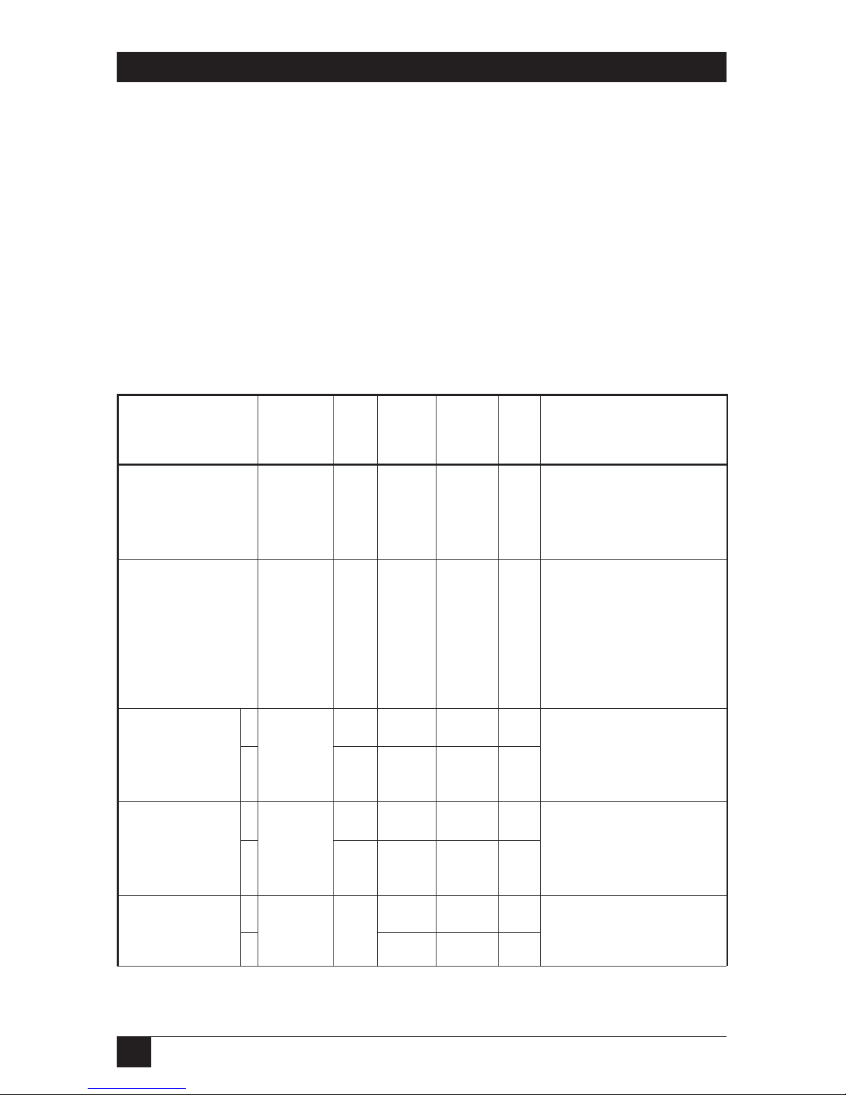
Table A-1 lists the signals and leads supported by the four Converter DTE
interfaces. Signals in different interfaces that are next to each other in this
table are analogous (that is, they perform roughly the same functions). This
means that the pinout of the RS-530-to-RS-449 adapter included with the RS449 models is also shown in this table; the adapter cable connects the RS-530
leads/signals to the V.36/RS-449 leads/signals listed beside them.
Figures A-1 through A-8 show how cables connecting different equipment
to the Converter’s interface connector should be pinned.
ITU-TSS V.35 RS-530 V.36/ X.21
Circuit Pin Pin RS-449 Pin
Pin(s)
101 A 1 1 1
102 B 7 19, 20, 8
37
103 P 2 4 2
S14 22 9
104 R 3 6 4
T16 2411
105 C 4 7 3
19 25 10
Table A-1. Interface-Connector Pinouts
Description
Chassis ground. Can be
isolated from Signal Ground
or tied to it.
Common ground for
signaling and for the DC
power supply. Can be
isolated from Shield or tied
to it.
Serial digital data from the
DTE. The data transitions
must occur on the rising
edge of the transmit clock.
Serial digital data sent to the
DTE. The data transitions
occur on the rising edge of
the clock.
The DTE raises this signal
when it wants to send data
through the Converter.
Signal
Names
Shield, Frame
Ground (FGND),
Protective
Ground (PGND)
Signal Ground
(SGND, SG);
V.36/RS-449
only: also Send
Common (SC)
and
Receive
Common (RC)
Send Data (SD),
Transmitted Data
(TD
), Trans
mit (T)
Receive(d) Data
(RD), Receive (R)
Request to Send
(RTS, RS),
Control (C)
A
B
A
B
A
B

41
APPENDIX: Pinouts
Table A-1 (continued). Interface-Connector Pinouts
ITU-TSS V.35 RS-530 V.36/ X.21
Circuit Pin Pin RS-449 Pin
Pin(s)
106 D 5 9 —
13 27 —
107 E 6 11 —
22 29 —
109 F 8 13 5
10 31 12
113 U 24 17 6*
W 11 35 13*
114 Y 15 5 6
AA 12 23 13
Description
Assuming it is ready to
receive, the Converter
raises this signal a few
moments after sensing RTS.
The Converter holds this
signal high while the
Converter is ON and is not
in local or remote digital
loopback.
The Converter holds this
signal high, lowering it only
if carrier is lost or DSRgoes
low.
An serial data-rate clock
input to the Converter from
a data source. Positive clock
transitions must correspond
to data transitions.
A serial data-rate clock
output from the Converter to
a data source. Positive clock
transitions correspond to
data transitions.
Signal
Names
Clear to Send
(CTS, CS)
Data Set
Ready
(DSR),
DCE
Ready
(DCER),
Dat
a Mode (DM)
Received Line
Signal Detector
(RLSD), Receiver
Ready (RR), Indication (I); a.k.a.
Data Carrier
Detect (DCD)
Serial Clock
Transmit Ext.
(SCTE), Terminal
Timing (TT),
T’mitter Signal
Element Timing
[DTE] (TSETT);
a.k.a. External
Clock (EXTC)
Serial Clock T’mit
(SCT),
Send Tim-
ing (ST)
, T’mitter
Signal Element
Timing [DCE]
(TSETC), Signal
Elem. Timing (S);
a.k.a. Transmit
Clock (TC)
A
B
A
B
A
B
A
B
A
B

42
G.703 CODIRECTIONAL CONVERTER
Table A-1 (continued). Interface-Connector Pinouts
ITU-TSS V.35 RS-530 V.36/ X.21
Circuit Pin Pin RS-449 Pin
Pin(s)
115 V 17 8 —
X9 26—
141 JJ 18 10 —
140 HH 21 14 —
142 KK 25 18 —
Description
A serial data-rate clock
output from the Converter to
a data sink. Positive clock
transitions correspond to
data transitions.
The DTE can raise this
signal to the Converter to
force it into local analog
loopback (see
Section 4.3.2).
The DTE can raise this
signal to the Converter to
force it into remote digital
loopback (see
Section 4.3.3).
The Converter raises this
signal to the DTE during any
test mode.
Signal
Names
Serial Clock Rcv.
(SCR),
Rcv. Tim-
ing (RT)
, Rec’ver
Signal Element
Timing [DCE]
(RSET); a.k.a.
Rcv. Clock (TC)
Local Analog
Loopback (LL)
Remote Digital
Loopback (RL)
Test Mode (TM)
A
B

43
APPENDIX: Pinouts
Figure A-1. Connecting a V.35 DTE to a V.35 Converter.
V.35
(DTE)
M/34
G.703
Codirectional
Converter
(DCE)
M/34
C RTS
D CTS
E DSR
F DCD
P TRANSMITTED DATA-A
S TRANSMITTED DATA-B
R RECEIVED DATA-A
T RECEIVED DATA-B
Y TRANSMITTER TIMING-A
AA TRANSMITTER TIMING-B
V RECEIVER TIMING-A
X RECEIVER TIMING-B
A PROTECTIVE GND
B SIGNAL GND
HH REMOTE LOOPBACK
JJ LOCAL LOOPBACK
KK TEST MODE
C
D
E
F
P
S
R
T
Y
AA
V
X
A
B
HH
JJ
KK

44
G.703 CODIRECTIONAL CONVERTER
Figure A-2. Connecting a V.35 DCE to a V.35 Converter.
V.35
(DCE)
M/34
G.703
Codirectional
Converter
(DCE)
M/34
C RTS
F DCD
P TRANSMITTED DATA-A
S TRANSMITTED DATA-B
R RECEIVED DATA-A
T RECEIVED DATA-B
V RECEIVER TIMING-A
X RECEIVER TIMING-B
A PROTECTIVE GND
B SIGNAL GND
U TRANSMITTER TIMING (DTE SOURCE)-A
W TRANSMITTER TIMING (DTE SOURCE)-B
H DTR
F
C
R
T
P
S
U
W
A
B
V
X
E

45
APPENDIX: Pinouts
Figure A-3. Connecting an X.21 DTE to an X.21 Converter.
X.21
(DTE)
DB15
G.703
Codirectional
Converter
(DCE
DB15
8Ga
5Ia
12 Ib
3Ca
10 Cb
2Ta
9Tb
4Ra
11 Rb
6Sa
13 Sb
1G
Ga 8
Ia 5
Ib 12
Ca 3
Cb 10
Ta 2
Tb 9
Ra 4
Rb 11
Sa 6
Sb 13
G1

46
G.703 CODIRECTIONAL CONVERTER
Figure A-4. Connecting an X.21 DCE to an X.21 Converter.
NOTE
The unit’s timing jumpers must be set to LBT-DCE21 (see Sections 2.2.2
and 3.3) for this type of connection to work.
X.21
(DCE)
DB15
G.703
Codirectional
Converter
(DTE)
DB15
5 INDICATION-A
12 INDICATION-B
3 CONTROL-A
10 CONTROL-B
2 TRANSMITTED DATA-A
9 TRANSMITTED DATA-B
4 RECEIVED DATA-A
11 RECEIVED DATA-B
6 SIGNAL ELEMENT TIMING-A
13 SIGNAL ELEMENT TIMING-B
8 SIGNAL GND
1 SHIELD
Ca 3
Cb 10
Ia 5
Ib 12
Ra 4
Rb 11
Ta 2
Tb 9
Sa 6
Sb 13
Ga 8
G1

47
APPENDIX: Pinouts
Figure A-5. Indirectly connecting a V.36/RS-449 DTE to a V.36/RS-449
Converter through the included adapter cable.
V.36
(DTE)
OR
RS-449
(DTE)
DB37
Adapter
Cable for
G.703
Codirectional
Converter
(DCE)
DB37
1 SHIELD
19,20,37 SG,RC,SC
7 RS-a
25 RS-b
13 RR-a
31 RR-b
9 CS-a
27 CS-b
11 DM-a
29 DM-b
5ST-a
23 ST-b
8RT-a
26 RT-b
4 SD-a
22 SD-b
6 RD-a
24 RD-b
10 LL
14 RL
18 TM
SHIELD 1
SG,RC,SC 19,20,37
RS-a 7
RS-b 25
RR-a 13
RR-b 31
CS-a 9
CS-b 27
DM-a 11
DM-b 29
ST-a 5
ST-b 23
RT-a 8
RT-b 26
SD-a 4
SD-b 22
RD-a 6
RD-b 24
LL 10
RL 14
TM 18

48
G.703 CODIRECTIONAL CONVERTER
Figure A-6. Indirectly connecting a V.36/RS-449 DCE to a V.36/RS-449
Converter through the included adapter cable.
V.36
(DCE)
OR
RS-449
(DCE)
DB37
Adapter
Cable for
G.703
Codirectional
Converter
(DCE)
DB37
19,20,37 SG,RC,SC
12 TR-a
30 TR-b
7 RS-a
25 RS-b
13 RR-a
31 RR-b
17 TT-a
35 TT-b
8RT-a
26 RT-b
4 SD-a
22 SD-b
6 RD-a
24 RD-b
1 SHIELD
SG,RC,SC 19,20,37
DM-a 11
DM-b 29
RR-a 13
RR-b 31
RS-a 7
RS-b 25
RT-a 8
RT-b 26
TT-a 17
TT-b 35
RD-a 6
RD-b 24
SD-a 4
SD-b 22
SHIELD 1

49
APPENDIX: Pinouts
Figure A-7. Directly connecting a V.36/RS-449 DTE to a V.36/RS-449
Converter (RS-530 interface connector).
V.36
(DTE)
OR
RS-449
(DTE)
37-pin
DB37
G.703
Codirectional
Converter
DB25
1 SHIELD
19,20,37 SG,RC,SC
7 RS-a
25 RS-b
13 RR-a
31 RR-b
9 CS-a
27 CS-b
11 DM-a
29 DM-b
5ST-a
23 ST-b
8RT-a
26 RT-b
4 SD-a
22 SD-b
6 RD-a
24 RD-b
10 LL
14 RL
18 TM
SHIELD 1
SIGNAL GND 7
RTS-a 4
RTS-b 19
DCD-a 8
DCD-b 10
CTS-a 5
CTS-b 13
DSR-a 6
DSR-b 22
TC-a 15
TC-b 12
RC-a 17
RC-b 9
TD-a 2
TD-b 14
RD-a 3
RD-b 16
LL 18
RL 21
TM 25

50
G.703 CODIRECTIONAL CONVERTER
Figure A-8. Directly connecting a V.36/RS-449 DCE to a V.36/RS-449
Converter (RS-530 interface connector).
V.36
(DCE)
OR
RS-449
(DCE)
DB37
G.703
Codirectional
Converter
(DCE)
DB25
19,20,37 SG,RC,SC
12 TR-a
30 TR-b
7 RS-a
25 RS-b
13 RR-a
31 RR-b
17 TT-a
35 TT-b
8RT-a
26 RT-b
4 SD-a
22 SD-b
6 RD-a
24 RD-b
1 SHIELD
SIGNAL GND 7
DSR-a 6
DSR-b 22
DCD-a 8
DCD-b 10
RTS-a 4
RTS-b 19
RC-a 17
RC-b 9
EXTC-a 24
EXTC-b 11
RD-a 3
RD-b 16
TD-a 2
TD-b 14
SHIELD 1

51
APPENDIX: Pinouts
Figure A-9. Connecting an RS-530 DTE to an RS-530 Converter.
RS-530
DTE
DB25
G.703
Codirectional
Converter
(DCE)
DB25
7 SIGNAL GND
6 DSR-a
22 DSR-b
5 CTS-a
13 CTS-b
4 RTS-a
19 RTS-b
8 DCD-a
10 DCD-b
15 TC-a
12 TC-b
17 RC-a
9 RC-b
2 TD-a
14 TD-b
3 RD-a
16 RD-b
18 LL
21 RL
25 TM
1 SHIELD
SIGNAL GND 7
DSR-a 6
DSR-b 22
CTS-a 5
CTS-b 13
RTS-a 4
RTS-b 19
DCD-a 8
DCD-b 10
TC-a 15
TC-b 12
RC-a 17
RC-b 9
TD-a 2
TD-b 14
RD-a 3
RD-b 16
LL 18
RL 21
TM 25
SHIELD 1

52
G.703 CODIRECTIONAL CONVERTER
Figure A-10. Connecting an RS-530 DCE to an RS-530 Converter.
RS-530
DCE
DB25
G.703
Codirectional
Converter
(DCE)
DB25
7 SIGNAL GND
20 DTR-a
23 DTR-b
4 RTS-a
19 RTS-b
8 DCD-a
10 DCD-b
24 EXTC-a
11 EXTC-b
17 RC-a
9 RC-b
2 TD-a
14 TD-b
3 RD-a
16 RD-b
1 SHIELD
SIGNAL GND 7
DSR-a 6
DSR-b 22
DCD-a 8
DCD-b 10
RTS-a 4
RTS-b 19
RC-a 17
RC-b 9
EXTC-a 24
EXTC-b 11
RD-a 3
RD-b 16
TD-a 2
TD-b 14
SHIELD 1

1000 Park Drive • Lawrence, PA 15055-1018 • 724-746-5500 • Fax 724-746-0746
© Copyright 1997. Black Box Corporation. All rights reserved.
 Loading...