

Page 1

Passive CCTV Hub (IC562A,IC563A)
Installation Guide
P/N: 94-000384-A, SE-000418-A
Page 2

Passive CCTV Hub Installation Guide
Page 2
Page 3

Passive CCTV Hub Installation Guide
Table of Contents
1. Overview....................................................................................................................4
1.1. Description.........................................................................................................4
1.2. Features .............................................................................................................4
2. Technical Specifications ............................................................................................5
3. Installation Procedure ...............................................................................................6
3.1. Parts List............................................................................................................6
3.2. Product Overview...............................................................................................6
3.3. Pre-Installation Checklist.....................................................................................7
3.4. Physical Installation.............................................................................................8
3.5. Installation Procedure - Model IC562A..............................................................9
3.6. Installation Procedure - Model IC563A............................................................13
4. Troubleshooting.......................................................................................................18
5. Distance Tables.......................................................................................................19
6. Product Warranty Policy.........................................................................................21
1.
Overview
1.1. Description
The Passive CCTV Hub allows video, remote power and PTZ control to be
transmitted via one 4-pair Cat 5 cable, thus eliminating the need to install multiple
cables for more efficient cabling in the security video environment. There are two
16-port models: IC562A; for coax video output and the IC563A; for twisted pair
video output.
Page 3
Page 4

Passive CCTV Hub Installation Guide
The Passive CCTV Hub works in conjunction with the IC440A, IC444A, IC453A,
IC452A, IC451A, IC560A, IC561A, IC454A and IC455A. The product features
a port switch to set the unit to Power-Thru or Pass-Thru mode.
1.2. Features
• Port switch to set unit to Pass-Thru Mode (IC452A) or Power-Thru Mode
(IC560A/IC561A)
• Pin configuration chart on unit
• Space efficient, rack-mountable
Page 4
Page 5

Passive CCTV Hub Installation Guide
2.
Technical Specifications
Specifications
Environment Composite video; NTSC, PAL, SECAM
Devices CCTV cameras, DVRs, monitors, switchers, multiplexers and other CCTV equip.
Transmission Transparent to the user.
Video
Bandwidth DC to 8 MHz.
Maximum Input 1.1Vp-p
Insertion Loss Less than 2 dB per pair over the frequency range from DC to 8 MHz
Return Loss Greater than 15 dB over the frequency range from DC to 8 MHz
Common Mode Rejection Greater than 40 dB @ 8 MHz
Max. Distance - Color Cat 3 –1,200 ft (365m); Cat 5 – 2,200 ft. (670m)*
*Shorter distances will result with DVR equipment. Typically 1,000 to 1,500 ft
Max. Distance - B&W Cat 3 –1,500 ft (457m); Cat 5 – 2,500 ft (762m)
Remote Power
Switch Mode Pass-Thru Mode (IC452A) Power-Thru Mode (IC560A/IC561A)
Number of twisted pairs Two (2) Three (3)
Max. Distance @ 24VAC*
*Based on 10% voltage drop at
camera. Longer distances may
be achieved @ 28 VAC.
Maximum Input Voltage 50 Volts (AC RMS/DC). Recommended Class II PSU with fuse protection per port
Maximum Current Rating 4.5A (AC RMS/DC)
2-Wire PTZ Control (i.e. RS-422, Manchester/Bi-Phase, half duplex RS485) – Pass-Thru Mode (IC452A)
Wiring Remote 2-wire PTZ control supported via one (1) twisted pair.
Maximum Distance Up to 4,000 ft (1.2 km) depending on the PTZ camera vendor**
Maximum Power Rating 50 Volts (AC RMS/DC); 3A (AC RMS/DC)
Mechanical & Environmental
Cable – UTP
Cable – Coax Impedance: 75 O at 1 MHz. (RG59/U). Max. 25 ft. of coax allowed end to end.
Connectors Video (Model IC562A): Sixteen (16) BNC-F
Port Configuration Switch Sets each port to Pass-Thru Mode (IC452A) or Power-Thru Mode (IC560A/IC561A)
RJ45 Pin Configuration* Signal IC452A Mode IC560A/IC561A Mode
*Reverse polarity sensitive Power A (+) 1, 3 1, 3, 5
Power B (-) 2, 6 2, 4, 6
Control (+) 4 Not used
Control (-) 5 Not used
Video BNC Center (Tip) 7 [T] opposite to IC440A 7 [T] opposite to IC440A
Video BNC Ground (Ring) 8 [R] opposite to IC440A 8 [R] opposite to IC440A
Temperature Operating: 0° to 55°C. Storage:-20° to 85°C. Humidity: up to 95%
Enclosure Black, anodized aluminum
Dimensions 19” (48.26 cm) W x 1.75” (4.4 cm) H x 2.0” ( 5.1 cm) D
Weight 2.3 lbs. (1.1kgs)
Warranty Lifetime
Order Information IC562A Passive CCTV Hub, UTP/Coax
5 VA: 350 ft (107m) 10 VA: 175 ft (53m)
20 VA: 90 ft (30m) 30 VA: 60 ft (20m)
**Please consult your CCTV equipment vendor for more detailed performance
specifications.
24 AWG or lower solid copper twisted pair wire impedance: 100 ohms at 1 MHz
Maximum capacitance: 20 pf/foot. Attenuation: 6.6 dB/1000 ft at 1 MHz
Video (Model IC563A): Sixteen (16) 2-pole screw terminals
Power: Sixteen (16) 2-pole screw terminals
Control: Sixteen (16) 2-pole screw terminals.
Combined signals: Sixteen (16) RJ45 jacks
IC563A Passive CCTV Hub, UTP/UTP
5 VA: 518 ft (170m) 10 VA: 259 ft (85 m)
20 VA: 130 ft (43 m) 30 VA: 86 ft (28 m)
Page 5
Page 6
Passive CCTV Hub Installation Guide
3.
Installation Procedure
3.1. Parts List
The Passive CCTV Hub comes with the following parts. Please verify that all pieces
are present before proceeding.
• Base Unit (Factory configuration: Power-Thru Mode (IC452A)
• Installation Guide
3.2. Product Overview
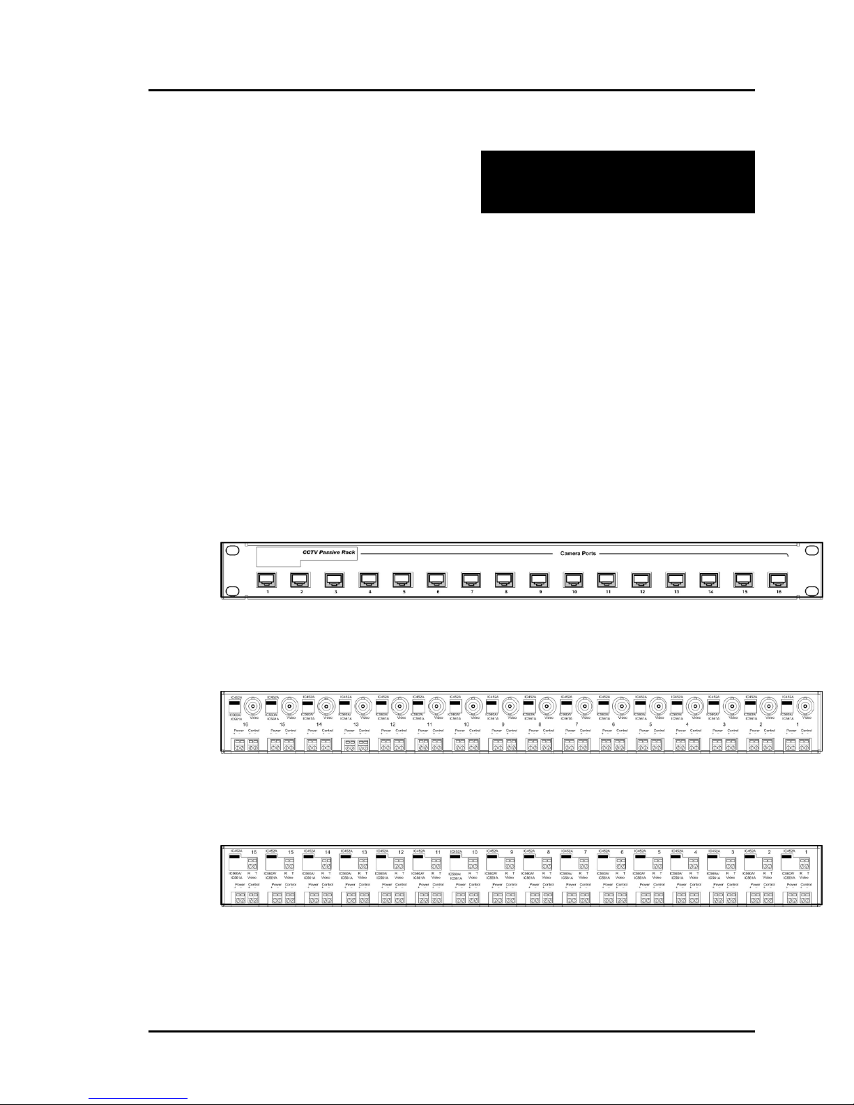
The external connections of the Passive CCTV Hub are detailed in the following
diagrams. Please familiarize yourself with them before installing the unit.
Figure 1: Front panel, all models
Figure 2: Rear panel, Model IC562A (UTP/Coax)
Page 6
Figure 3: Rear panel: Model IC563A (UTP/UTP)
Page 7

Passive CCTV Hub Installation Guide
3.3. Pre-Installation Checklist
The Passive CCTV Hub provides a centralized sixteen (16) port CCTV copper
twisted pair cabling solution.
1. The Passive CCTV Hub is used in a CCTV installation to manage the video,
power and control connections between the CCTV cameras and the head-end.
2. There are two (2) models of the Passive CCTV Hub; IC562A and IC563A.
The difference between the IC562A and IC563A is that the video portion of the
IC562A incorporates a video balun at each port and is connected to the DVR
via coaxial cable. The video portion of the IC563A is fully twisted pair on the
input and output and connected to the DVR via twisted pair cable. In order to
convert from twisted pair back to coax, a CCTV video balun is connected at
each DVR port.
3. The products feature a switch at each port to select between Pass-Thru Mode
(IC452A compatible) or Power-Thru Mode (IC560A/IC561A compatible)
depending on the cabling configuration.
4. The Passive CCTV Hub works in conjunction with Black Box’s other CCTV
products including the IC440A, IC444A, IC453A, IC452A, IC451A, IC560A,
IC561A, IC454A and IC455A). The passive CCTV Baluns are connected at
the CCTV camera.
5. The Passive CCTV Hub works with CCTV cameras that have built -in twisted
pair baluns. It may be necessary to reverse the polarity of the wires first.
Distance performance may vary.
Page 7
Page 8
Passive CCTV Hub Installation Guide
3.4. Physical Installation
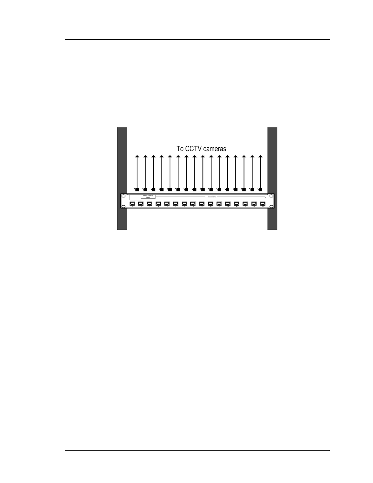
The Passive CCTV Hub is a 1U, 19” rackmount unit. The factory default switch
settings of each port is Pass-Thru Mode (IC452A).
1. Select the final destination for the product in the relay rack and install the unit
using standard rackmount screws.
Figure 4: Rack-m ount installation
Page 8
Page 9
Passive CCTV Hub Installation Guide
3.5. Installation Procedure – Model IC562A
The Passive CCTV Hub, Model IC562A features BNC connectors on the video
portion of the device, thereby allowing it to be connected directly to the DVR via
coaxial cable. In order to install the product in this configuration, please follow the
steps below:
1. Install the Passive CCTV Hub in its final location. Please verify that the distance
between the rack and cameras are within Black Box specifications.
2. Connect a Black Box passive CCTV Balun (Black Box p/n IC440A, IC444A,
IC452A, IC451A, IC560A or IC561A) to each CCTV camera video output.
Please refer to the appropriate CCTV balun installation guide for details.
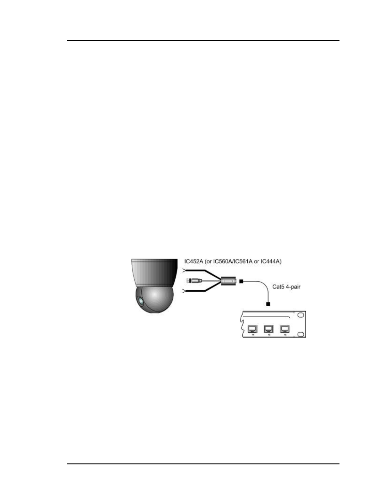
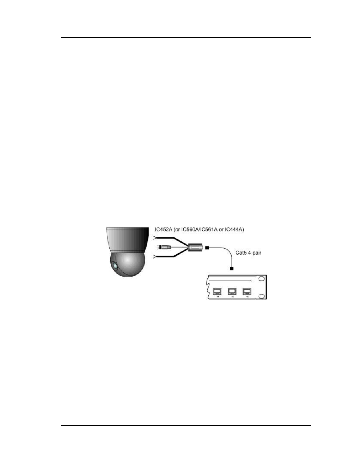
3. Connect one Cat5 cable from each camera to one of the modular RJ45 ports on
the front of the Passive CCTV Hub (fig 5). Please ensure that EIA 568 wiring
and straight-through polarity is respected between the CCTV balun and the
rack. The use of other Cat5 connection hardware such as patch panels and 110
blocks may be used.
Figure 5: Camera connection
Page 9
Page 10
Passive CCTV Hub Installation Guide
Port Switch Settings:
4. For each camera port, determine whether video, power and/or control is to be
transmitted via the same Cat5 cable. If only video is to be transmitted, then the
Power/Control terminals and port switch may be disregarded.
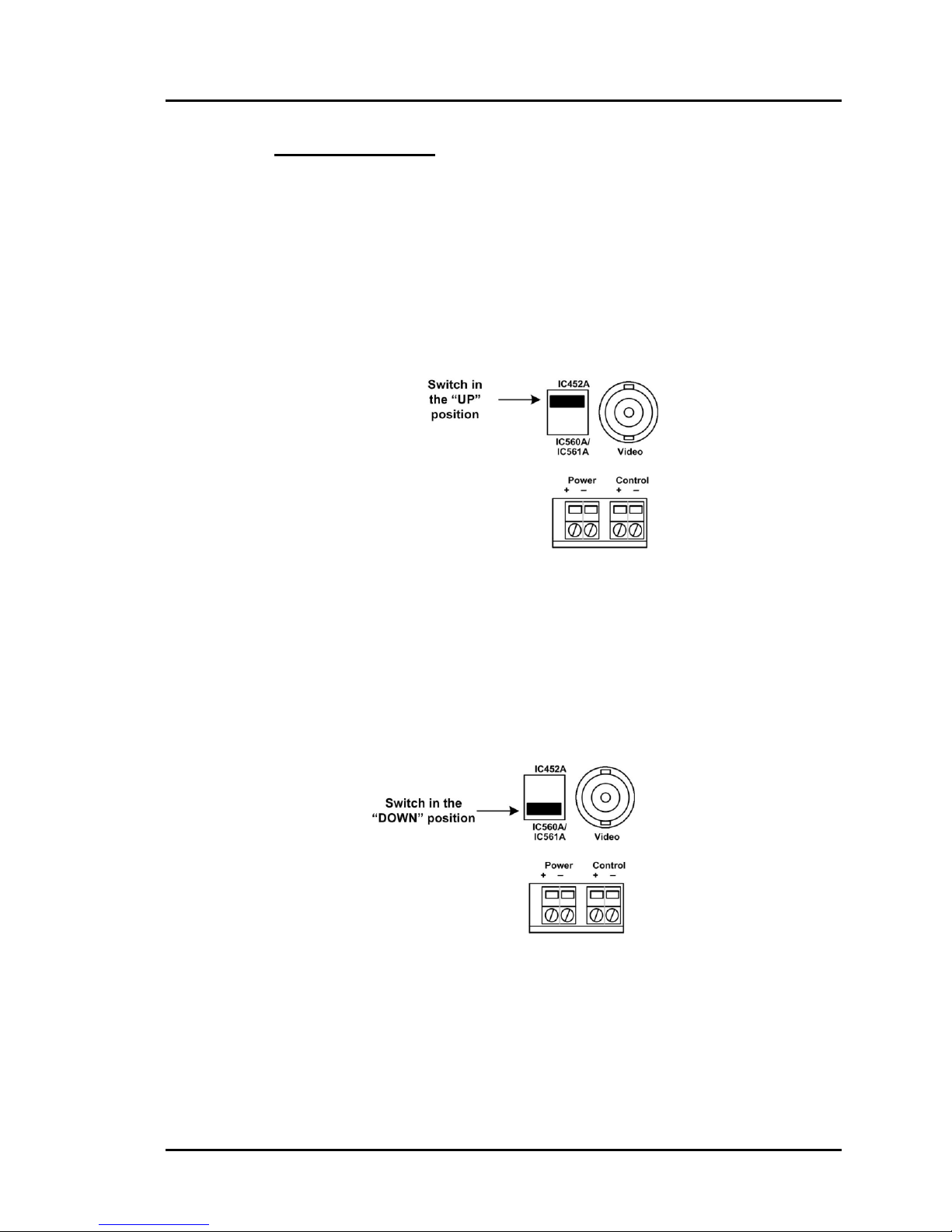
5. In order to transmit video on one (1) twisted pair, remote power on two (2)
twisted pairs and control on one (1) twisted pair, set the port switch to PassThru Mode (IC452A) using a small flathead screwdriver, as shown in fig 6.
Ensure that there is a CCTV Pass-Thru Balun (IC452A) at the camera.
Figure 6: Port Setting – Pass-Thru Mode (IC452A)
6. In order to transmit video on one (1) twisted pair and remote power on three (3)
twisted pairs, set the port switch to Power-Thru Mode (IC560A/IC561A) using
a small flathead screwdriver (fig 7). Ensure that there is a CCTV Power-Thru
Balun (IC560A or IC561A) at the camera.
Figure 7: Port Setting – Power-Thru Mode (IC560A/IC561A)
Page 10
Page 11
Passive CCTV Hub Installation Guide
Output Connections:
Video:
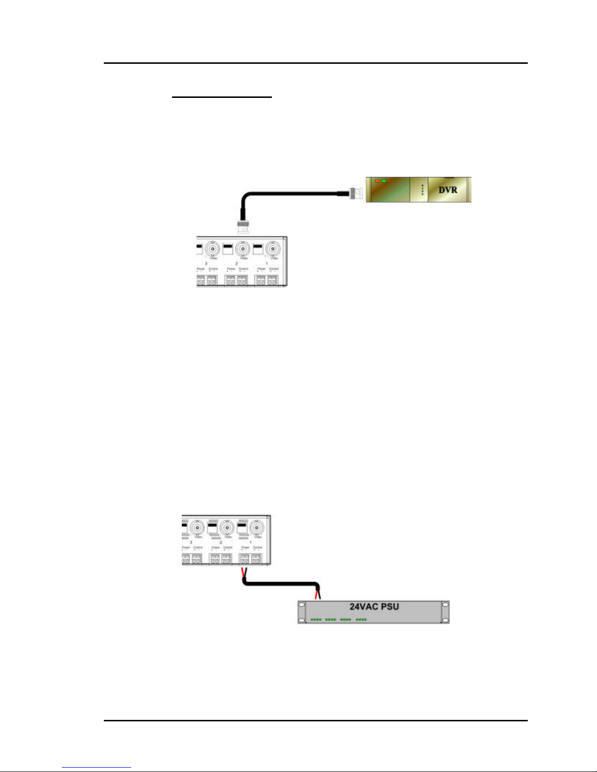
7. Connect one coax cable between each video output port on the rack and the
DVR video input (fig 8).
Figure 8: Video connection, Model IC562A
Remote Power:
8. If remote power is being transmitted to the camera, verify that the distance
between the camera and the hub is within Black Box specifications. Please
consult the distance charts at the back of the installation guide. When the port
switch is set to Pass-Thru Mode (IC452A), two (2) twisted pairs are used for
remote power. When the port switch is set to Power-Thru Mode
(IC560A/IC561A), three (3) twisted pairs are used for remote power thus
supporting greater distance.
9. Connect two (2) wires between the power terminals of the hub to the remo te
low voltage power supply (fig 9). It is recommended to use a Class II
power supply with fuse protection on each output port.
Figure 9: Remote power connection, Model IC562A
Page 11
Page 12
Passive CCTV Hub Installation Guide
PTZ Control:
10. If PTZ Control is to be transmitted to the camera, verify that the distance
between the camera and the hub is within the distance specifications for sending
PTZ control over twisted pair. Consult the PTZ equipment vendor for maximum
distances. Please ensure that the port switch is set to Pass-Thru Mode
(IC452A). When the port switch is set to Pass-Thru Mode (IC452A), one (1)
twisted pair is used for PTZ control. For optimum results, it is recommended to
use control protocols such as RS -422, RS-485 or Bi-phase. Due to crosstalk
issues, RS-232 is not recommended.
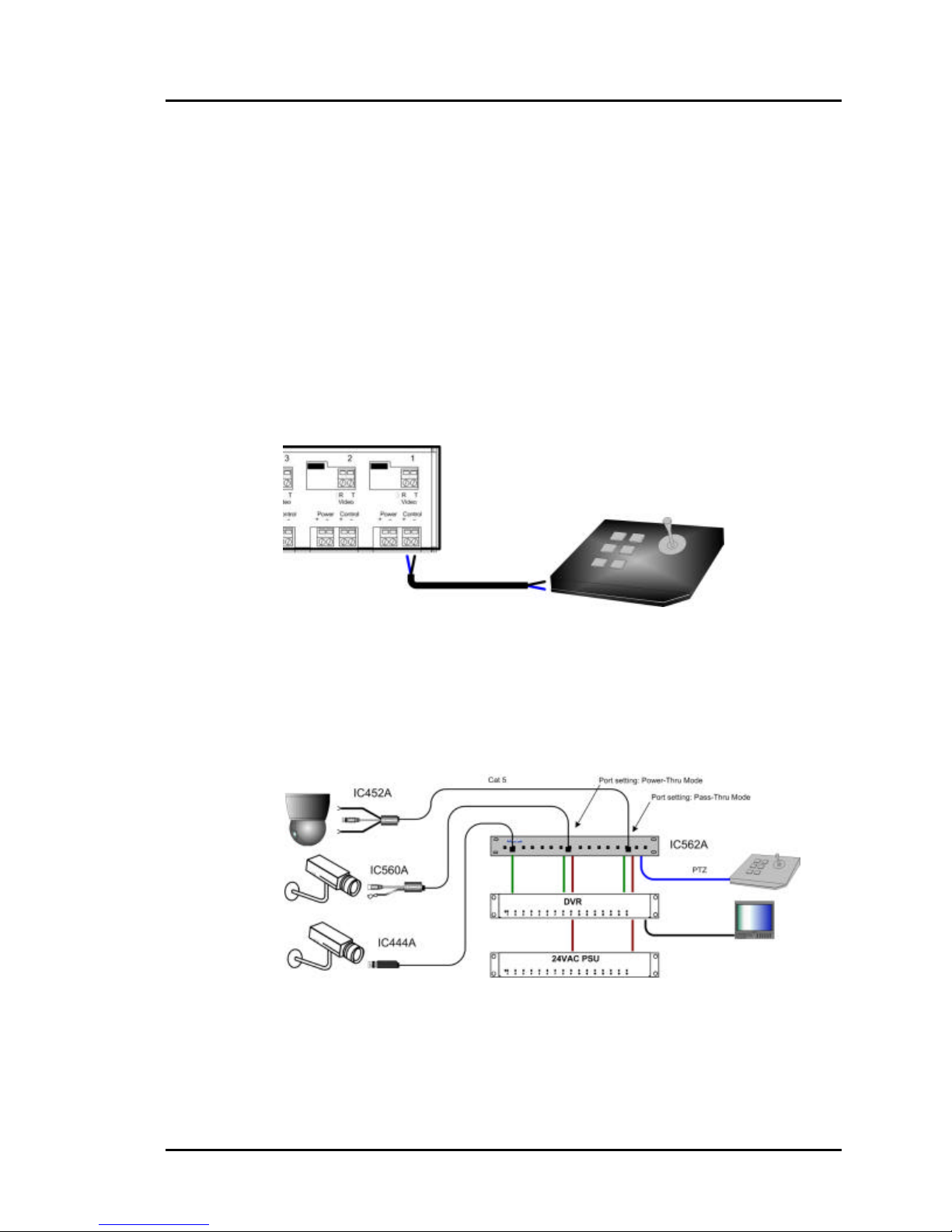
11. Connect two (2) wires between the PTZ controller and the “Control” terminals
on the hub (fig 10).
Figure 10: PTZ connection, Model IC562A
12. Power on the CCTV equipment; cameras, remote power supply, PTZ
controller.
13. The following diagram shows a typical configuration.
Figure 11: Typical Configuration, Model IC562A
Page 12
Page 13
Passive CCTV Hub Installation Guide
3.6. Installation Procedure – Model IC563A
The Passive CCTV Hub, Model IC563A features screw terminal connectors on the
video portion of the device, thereby allowing it to be connected via twisted pair to
the head end equipment (DVR). Video baluns, such as the IC444A, must be used
at the DVR to convert back to coaxial cable. In order to install the product in this
configuration, please follow the steps below:
1. Install the Passive CCTV Hub in its final location. Please verify that the distance
between the cameras and the head end are within Black Box specifications.
2. Connect a Black Box passive CCTV Balun (Black Box p/n IC440A, IC444A,
IC452A, IC451A, IC560A or IC561A) to each CCTV camera video output.
Please refer to the appropriate CCTV balun installation guide for details.
3. Connect one Cat5 cable from each camera to one of the modular RJ45 ports on
the front of the Passive CCTV Hub (fig 12). Please ensure that EIA 568 wiring
and straight-through polarity is respected between the CCTV balun and the
rack. The use of other Cat5 connection hardware such as patch panels and 110
blocks may be used.
Page 13
Figure 12: Camera connection
Page 14
Passive CCTV Hub Installation Guide
Port Switch Settings:
4. For each camera port, determine whether video, power and/or control is to be
transmitted via the same Cat5 cable. If only video is to be transmitted, then the
Power/Control terminals and port switch may be disregarded.
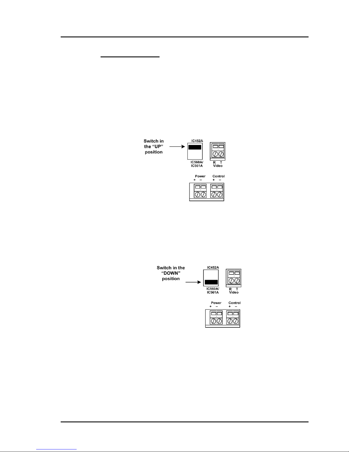
5. In order to transmit video on one (1) twisted pair, remote power on two (2)
twisted pairs and control on one (1) twisted pair, set the port switch to PassThru Mode (IC452A) as shown in figure 13. Ensure that there is a CCTV
Pass-Thru Balun (IC452A) at the camera.
Figure 13: Port Setting – Pass-Thru Mode (IC452A)
6. In order to transmit video on one (1) twisted pair and remote power on three (3)
twisted pairs, set the port switch to Power-Thru Mode (IC560A/IC561A) as
shown in figure 14. Ensure that there is a CCTV Power-Thru Balun (IC560A or
IC561A) at the camera.
Figure 14: Port Setting – Power-Thru Mode (IC560A/IC561A)
Page 14
Page 15
Passive CCTV Hub Installation Guide
Output Connections:
Video:
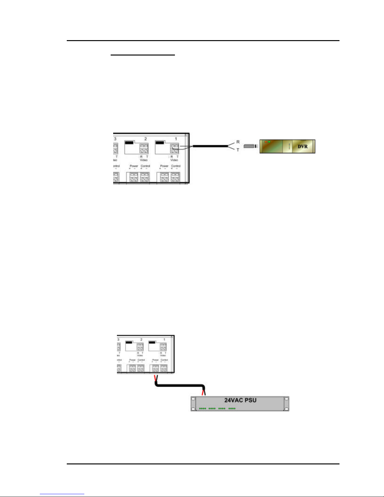
7. Install a CCTV balun on each port of the DVR. The products that may be
connected include; IC440A, IC444A, IC453A, 5000023 or IC455A.
8. Connect one (1) twisted pair for video between the hub and the balun on the
DVR (fig 15).
Figure 15: Video connection, Model IC563A
Remote Power:
9. If remote power is being transmitted to the camera, verify that the distance
between the camera and the hub is within Black Box specifications. Please
consult the distance charts at the back of the installation guide. When the port
switch is set to Pass-Thru Mode (IC452A), two (2) twisted pairs are used for
remote power. When the port switch is set to Power-Thru Mode
(IC560A/IC561A), three (3) twisted pairs are used for remote power thus
supporting greater distance.
10. Connect two (2) wires between the power terminals of the hub to the remote
low voltage power supply (fig 16). It is recommended to use a Class II
power supply with fuse protection on each output port.
Figure 16: Remote power connection, Model IC563A
Page 15
Page 16
Passive CCTV Hub Installation Guide
PTZ Control:
11. If PTZ Control is to be transmitted to the camera, verify that the distance
between the camera and the hub is within the distance specifications for sending
PTZ control over twisted pair. Consult the PTZ equipment vendor for maximum
distances. Please ensure that the port switch is set to Pass-Thru Mode
(IC452A). When the port switch is set to Pass-Thru Mode (IC452A), one (1)
twisted pair is used for PTZ control. For optimum results, it is recommended to
use control protocols such as RS -422, RS-485 or Bi-phase. Due to crosstalk
issues, RS-232 is not recommended.
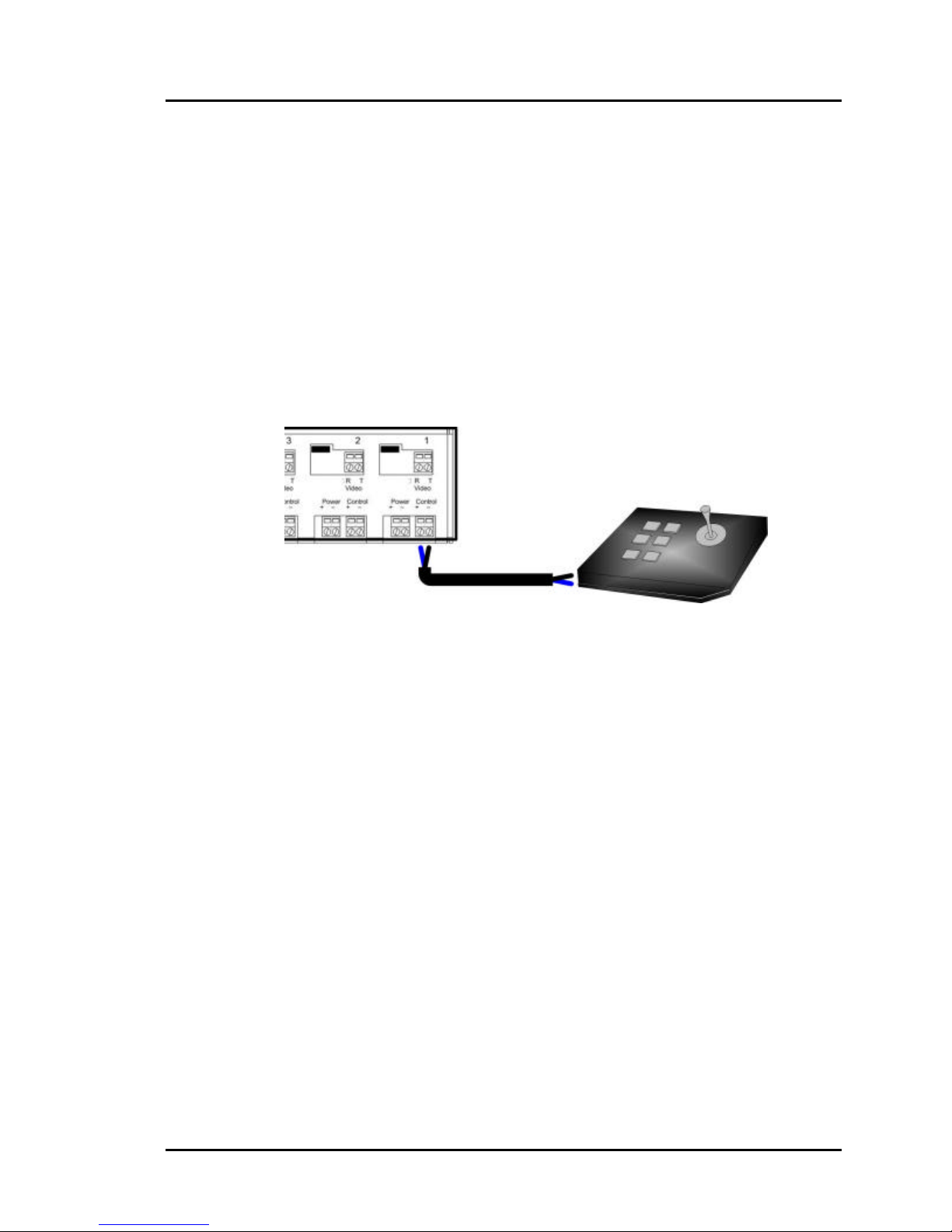
12. Connect two (2) wires between the PTZ controller and the “Control” terminals
on the hub (fig 17).
Figure 17: PTZ connection, Model IC563A
Page 16
Page 17
Passive CCTV Hub Installation Guide
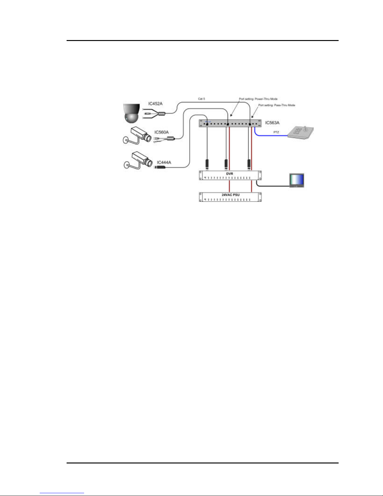
13. Power on the CCTV equipment; cameras, remote power supply, PTZ
controller. The following diagram shows a typical configuration.
Figure 18: Typical Configuration, Model IC563A
Page 17
Page 18

Passive CCTV Hub Installation Guide
4.
Troubleshooting
The following chart describes some of the problem symptoms, the probable causes and possible
solutions. If the information below does not solve the problem, please contact Black Box
Technical Support.
Picture Probable Causes Possible Solutions
No video image • Power-off. • Check power supplies of CCTV
equipment. Check power supply fuse.
• Wrong pin
configuration
• Defective CCTV
Balun
Poor image quality,
distortions, interference
Picture loses color, faded
or weak
• Wires reversed on
• Split pair • Check if the UTP pairs are split and
• Lower grade UTP
No power or intermittent
power at camera
• Distance exceeded • Verify distance specifications for remote
PTZ controls not
responding
• EMI interference
• Wires reversed on
signal pair on one
side
• Split pair
• Exceeded distance
specifications
• Lower grade UTP
cable is introducing
high losses
signal pair on one
side
cable is introducing
high signal losses.
• Wrong pin
configuration.
• Wrong pin config • Check wiring.
• Check pin configuration and verify
straight-through wiring.
• Change CCTV baluns for another pair.
• Check that wiring is not too close to
transformers and lighting ballasts
• Make sure that the wires on the signal
pair are not reversed on one side.
• Check if the UTP pairs are correct (not
split)
• Check DC loop resistance and verify if
distance spec is exceeded
• Reduce cable length or eliminate high-loss
components
• Replace cable by higher grade
• Make sure that the wires on the signal
pair are not reversed on one side.
correct. Each signal pair must be twisted.
• Use signal repeater for extended distance
or replace cable by higher grade.
• Check wiring
power. Move power closer to camera.
When contacting Black Box Technical Support at 724-746-5500, please have the following
information ready: Unit model number, cabling lay-out, model of camera and DVR used, power
supply voltage, camera wattage, cable length, cable type, description of problem, list of tests
performed.
Page 18
Page 19

Passive CCTV Hub Installation Guide
5.
Distance Tables
The following tables provide the maximum distances for remote power via Cat5 twisted pair
when a port on the Passive CCTV Hub is set to Pass-Thru Mode (IC452A) or Power-Thru
Mode (IC560A/IC561A).
Pass-Thru Mode (IC452A) – Two (2) Twisted Pairs
Voltage Pcam
(W)
12 VDC/AC 5 10.80 86 28
12VDC/AC
camera
20 10.80 22 7
30 10.80 14 5
10 10.80 43 14
Vcam1 min
(V)
Dist Spec2 max
(Feet)
Dist Spec2
max (m)
40 10.80 11 4
50 10.80 9 3
24 VAC 5 21.60 346 113
24VAC camera 10 21.60 173 57
20 21.60 86 28
30 21.60 58 19
40 21.60 43 14
50 21.60 35 11
28 VAC 5 21.60 922 302
24VAC camera 10 21.60 461 151
20 21.60 230 76
30 21.60 154 50
40 21.60 115 38
50 21.60 92 30
Page 19
Page 20

Passive CCTV Hub Installation Guide
Power-Thru Mode (IC560A/IC561A)
Voltage Pcam
(W)
12 VDC/AC 5 10.80 130 43
Vcam1 min
(V)
Dist Spec2 max
(Feet)
Dist Spec2
max (m)
12VDC
AC camera
20 10.80 32 11
30 10.80 22 7
40 10.80 16 5
50 10.80 13 4
24 VAC 5 21.60 518 170
24VAC
camera
20 21.60 130 43
30 21.60 86 28
40 21.60 65 21
50 21.60 52 17
28 VAC 5 21.60 1382 454
10 10.80 65 21
10 21.60 259 85
24VAC
camera
20 21.60 346 113
30 21.60 230 76
40 21.60 173 57
50 21.60 138 45
10 21.60 691 227
Notes:
1. Distances are specified for temperatures of 20 oC to 30oC
2. Maximum distances based on 10% loss of voltage. For 28VAC, a 24VAC camera was used.
3. Distances specified are 90% of distances calculated.
4. If 22AWG gage wire is used, there would be an increase in distance of approximately 56%.
Page 20
 Loading...