

CUSTOMER
SUPPORT
INFORMATION
Order toll-free in the U.S. 24 hours, 7 A.M. Monday to midnight Friday: 877-877-BBOX
FREE technical support, 24 hours a day, 7 days a week: Call 724-746-5500 or fax 724-746-0746
Mail order: Black Box Corporation, 1000 Park Drive, Lawrence, PA 15055-1018
Web site: www.blackbox.com • E-mail: info@blackbox.com
DECEMBER 1998
IC500A
IC501A
SCSI Fiber Optic Bus Extenders
IC500A 7/12/00 12:38 PM Page 901
FIBER
POWER
SELF
TEST
LINK ACTIVE
BUS ACTIVE
LINK ERROR
EXTENDER
SCSI FIBER OPTIC
COAX
LINK
TEST

1
TRADEMARKS
TRADEMARKS USED IN THIS MANUAL
Windows NT is a trademark, and Windows is a registered trademark, of Microsoft
Corporation.
UL is a registered trademark of Underwriters Laboratories Incorporated.
Any trademarks mentioned in this manual are acknowledged to be the property of
the trademark owners.
IC500A 7/12/00 12:38 PM Page 1

2
SCSI FIBER OPTIC BUS EXTENDERS
FEDERAL COMMUNICATIONS COMMISSION
AND
CANADIAN DEPARTMENT OF COMMUNICATIONS
RADIO FREQUENCY INTERFERENCE STATEMENTS
This equipment generates, uses, and can radiate radio frequency energy and if not
installed and used properly, that is, in strict accordance with the manufacturer’s
instructions, may cause interference to radio communication. It has been tested
and found to comply with the limits for a Class A computing device in accordance
with the specifications in Subpart J of Part 15 of FCC rules, which are designed to
provide reasonable protection against such interference when the equipment is
operated in a commercial environment. Operation of this equipment in a
residential area is likely to cause interference, in which case the user at his own
expense will be required to take whatever measures may be necessary to correct the
interference.
Changes or modifications not expressly approved by the party responsible for
compliance could void the user’s authority to operate the equipment.
This digital apparatus does not exceed the Class A limits for radio noise emission from digital
apparatus set out in the Radio Interference Regulation of the Canadian Department of
Communications.
Le présent appareil numérique n’émet pas de bruits radioélectriques dépassant les limites
applicables aux appareils numériques de la classe A prescrites dans le Règlement sur le
brouillage radioélectrique publié par le ministère des Communications du Canada.
IC500A 7/12/00 12:38 PM Page 2

3
NOM STATEMENT
NORMAS OFICIALES MEXICANAS (NOM)
ELECTRICAL SAFETY STATEMENT
INSTRUCCIONES DE SEGURIDAD
1. Todas las instrucciones de seguridad y operación deberán ser leídas antes de
que el aparato eléctrico sea operado.
2. Las instrucciones de seguridad y operación deberán ser guardadas para
referencia futura.
3. Todas las advertencias en el aparato eléctrico y en sus instrucciones de
operación deben ser respetadas.
4. Todas las instrucciones de operación y uso deben ser seguidas.
5. El aparato eléctrico no deberá ser usado cerca del agua—por ejemplo, cerca
de la tina de baño, lavabo, sótano mojado o cerca de una alberca, etc..
6. El aparato eléctrico debe ser usado únicamente con carritos o pedestales que
sean recomendados por el fabricante.
7. El aparato eléctrico debe ser montado a la pared o al techo sólo como sea
recomendado por el fabricante.
8. Servicio—El usuario no debe intentar dar servicio al equipo eléctrico más allá
a lo descrito en las instrucciones de operación. Todo otro servicio deberá ser
referido a personal de servicio calificado.
9. El aparato eléctrico debe ser situado de tal manera que su posición no
interfiera su uso. La colocación del aparato eléctrico sobre una cama, sofá,
alfombra o superficie similar puede bloquea la ventilación, no se debe colocar
en libreros o gabinetes que impidan el flujo de aire por los orificios de
ventilación.
10. El equipo eléctrico deber ser situado fuera del alcance de fuentes de calor
como radiadores, registros de calor, estufas u otros aparatos (incluyendo
amplificadores) que producen calor.
11. El aparato eléctrico deberá ser connectado a una fuente de poder sólo del
tipo descrito en el instructivo de operación, o como se indique en el aparato.
IC500A 7/12/00 12:38 PM Page 3

4
SCSI FIBER OPTIC BUS EXTENDERS
12. Precaución debe ser tomada de tal manera que la tierra fisica y la polarización
del equipo no sea eliminada.
13. Los cables de la fuente de poder deben ser guiados de tal manera que no
sean pisados ni pellizcados por objetos colocados sobre o contra ellos,
poniendo particular atención a los contactos y receptáculos donde salen del
aparato.
14. El equipo eléctrico debe ser limpiado únicamente de acuerdo a las
recomendaciones del fabricante.
15. En caso de existir, una antena externa deberá ser localizada lejos de las lineas
de energia.
16. El cable de corriente deberá ser desconectado del cuando el equipo no sea
usado por un largo periodo de tiempo.
17. Cuidado debe ser tomado de tal manera que objectos liquidos no sean
derramados sobre la cubierta u orificios de ventilación.
18. Servicio por personal calificado deberá ser provisto cuando:
A: El cable de poder o el contacto ha sido dañado; u
B: Objectos han caído o líquido ha sido derramado dentro del aparato; o
C: El aparato ha sido expuesto a la lluvia; o
D: El aparato parece no operar normalmente o muestra un cambio en su
desempeño; o
E: El aparato ha sido tirado o su cubierta ha sido dañada.
IC500A 7/12/00 12:38 PM Page 4

5
TABLE OF CONTENTS
Contents
Chapter Page
1. Specifications ............................................................................................................................6
2. Introduction ..............................................................................................................................8
2.1 Description......................................................................................................................8
2.2 Features ..........................................................................................................................8
3. Installation ..............................................................................................................................11
3.1 Unpacking Your Extender ..........................................................................................11
3.2 AC Line Voltage............................................................................................................11
3.3 Placement......................................................................................................................11
3.4 Cable Recommendations ............................................................................................11
3.5 Connecting the SCSI Fiber Optic Bus Extender to the SCSI Bus ............................12
3.6 Ensuring Proper SCSI Bus Termination ....................................................................12
3.7 Connecting a Fiberoptic Cable ..................................................................................12
3.8 Connecting a DB9 Coax Cable....................................................................................13
3.9 Verify Communications ..............................................................................................14
4. Operator Controls and Indicators ........................................................................................15
4.1 AC Switch ......................................................................................................................15
4.2 Indicators ......................................................................................................................15
4.3 Front-Panel Keypad......................................................................................................16
5. Interfacing Requirements ......................................................................................................17
5.1 SCSI Cable Interface Requirements ..........................................................................17
5.2 Internal/External Terminator Options......................................................................18
5.3 Internal Terminator Power and Fuse ........................................................................18
5.4 Selecting Internal Terminator Power ........................................................................19
5.5 RS-232 Interface Pin Assignment ................................................................................19
5.6 Internal RS-232 Jumper Block ....................................................................................20
5.7 Rear-Panel Option Switches ........................................................................................20
5.8 RS-232 Remote Operation Commands ......................................................................21
5.9 ASCII Character Reference for SCSI Fiber Optic Bus Extender Box Selection......23
5.10 Windows Software ........................................................................................................24
5.11 Connecting Multiple SCSI Fiber Optic Bus Extenders ............................................24
5.12 Rack Mount Installation ..............................................................................................25
5.13 Fiberoptic Cable Requirements ..................................................................................26
6. Operation ................................................................................................................................27
6.1 SCSI Fiber Optic Bus Extender Operation ................................................................27
6.2 System Performance ....................................................................................................27
6.3 System Configuration Options ....................................................................................27
7. SCSI Technical Information ..................................................................................................29
7.1 SCSI Basics ....................................................................................................................29
7.2 SCSI Installation Tips ..................................................................................................30
7.3 SCSI Interface Signal Descriptions ............................................................................31
IC500A 7/12/00 12:38 PM Page 5

6
SCSI FIBER OPTIC BUS EXTENDERS
1. Specifications
SCSI Interface
Maximum Data Rate..............................................40 MB per second
Wide SCSI Connector ..........................................68-pin
Narrow SCSI Connector........................................50-pin
SCSI to Fiber to SCSI Conversion Delay..............125 ns
Internal Terminator Power ..................................1 amp
Asynchronous and synchronous compatible
Conforms to ANSI X3.131 and X3T9.2 specifications
SCSI 1, 2, and SCSI 3 compatible
Resettable internal TERMPWR fuse
IC500A....................................................................Single-ended SCSI
Maximum Cable Length..............................19.7 feet (6 meters)
Maximum Slew Rate ....................................3 ns
Active Internal Bus Termination
IC501A....................................................................Differential SCSI
Maximum Cable Length..............................82 feet (25 meters)
Maximum Slew Rate ....................................3 ns
Passive Internal Bus Termination
Fiberoptic Link Interface
Maximum fiber cable length (both models):
6500 feet (2 km) with 8/125-µm single-mode fiber
1800 feet (550 meters) with 62.5/125-µm multimode fiber
Fiberoptic Serial Data Rate ..................................1.0625 Gigabits per second
Fiberoptic Connector Type ..................................SC
Optical Wavelength ..............................................850/1300 nm
Typical BER (Bit Error Rate)................................10 to 14
Coax Link Interface
Maximum coax cable length ................................100 feet (30 meters)
Impedance ....................................................150 ohms
Recommended Cable ..................................Gore FCN 1008-L
IC500A 7/12/00 12:38 PM Page 6

7
CHAPTER 1: Specifications
Serial-Port Interface—SCSI Fiber Optic Bus Extender Control
Data Rate................................................................9600/19200 baud
Mode ......................................................................No parity, 8 bits, 1 stop bit
Maximum Cable Length ......................................50 feet (15 meters)
Rear-Panel Connector ..........................................DB9 female
Serial-Port Interface—Extension
Data Rate................................................................1200 bps to 112 kbps
Mode ......................................................................All modes
Maximum Cable Length ......................................50 feet (15 meters)
Rear-Panel Connector ..........................................DB9 female
Physical
Temperature..........................................................32 to 131°F (0 to 55°C)
Humidity ................................................................Up to 90% relative humidity
Power......................................................................90 to 260 VAC, 15 W, 48 to 65 Hz
Size..........................................................................1.7"H x 14.7"W x 8.1"D
(4.3 x 37.3 x 20.6 cm)
Weight ....................................................................3 lb. (1.4 kg)
Maximum Fiber Cable
Code Description
Maximum Fiber Cable
IC500A Single-ended/Wide 2 km
IC501A Differential/Wide 2 km
Agency Approvals
UL®, CUL, CE, FCC Class A
IC500A 7/12/00 12:38 PM Page 7
8
SCSI FIBER OPTIC BUS EXTENDERS
2. Introduction
2.1 Description
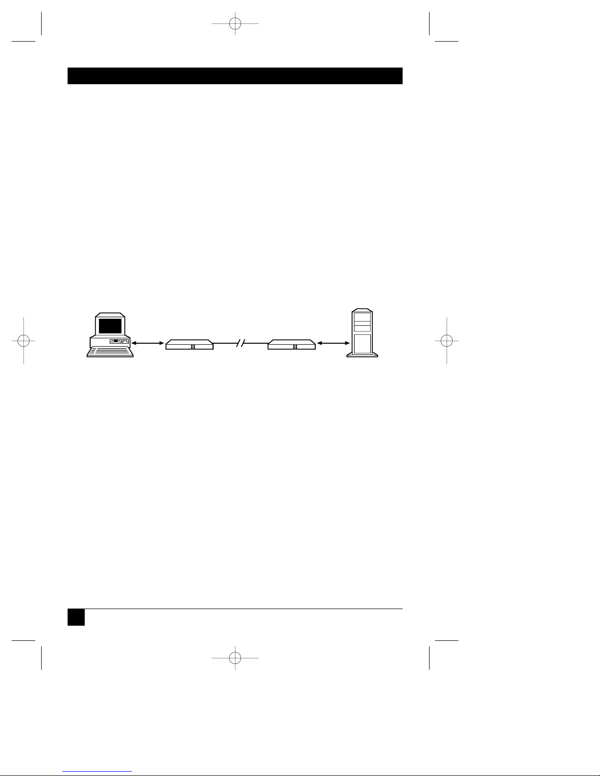
The SCSI Fiber Optic Bus Extender lets you surpass the distance limitation of the
single-ended and differential SCSI bus. The SCSI bus is one of the most popular
interfaces used to connect additional devices to a computer system. With the SCSI
Fiber Optic Bus Extender, SCSI components such as disk drives, CD-ROM memory
systems, RAID arrays, tape backups, and SCSI laser printers can be located up to
6500 feet (2 km) from the host computer.
Because the SCSI Fiber Optic Bus Extender is completely transparent to your SCSI
system, additional computer software is not needed for installation or operation.
Figure 2-1. Typical SCSI Fiber Optic Bus Extender Configuration.
2.2 Features
• Extends SCSI bus to 6500 feet (2 km)
• 40 MB per second throughput
• Ultra SCSI compatible
• 30-foot (100-meter) coax link standard
• RS-232 serial-port passthrough
• SCSI 1, SCSI 2, SCSI 3 compatible
• Single-ended or differential SCSI interface
30 to 10,000-ft.
Fiberoptic Link
SCSI Fiber Optic
Bus Extender
SCSI Fiber Optic
Bus Extender
Wide SCSI
Wide SCSI
IC500A 7/12/00 12:38 PM Page 8

9
CHAPTER 2: Introduction
• Fiber-channel-compatible optical link
• Standard SC connectors
• Internal bus termination
• No additional software required
• Advanced SCSI Fiber Optic Bus Extender Control software for remote control
• Transparent to the SCSI system
• Does not require a SCSI bus ID
The SCSI Fiber Optic Bus Extender supports Ultra SCSI, 40-MB-per-second, wide
and narrow devices in asynchronous or synchronous mode. The Extender gives
you the Ultra and Fast SCSI performance available in top-of-the-line computers
and peripheral devices. Its advanced proprietary design enables the Extender to
maintain complete SCSI command functionality while remaining transparent to
you.
The Extender includes 68- and 50-pin high-density SCSI-2 connectors for narrow
and wide devices.
Internal bus terminators are switch-selectable to support flexible installations.
A standard SC duplex fiberoptic connector supports a fiberoptic interface between
local and remote units.
The SCSI Fiber Optic Bus Extender also includes two duplex coaxial interfaces to
support shorter SCSI extender distances.
The SCSI Fiber Optic Bus Extender can be operated and controlled via the remote
RS-232 interface using the included SCSI Fiber Optic Bus Extender Control
software. Standard modem software can also be used to control the Extender. Up
to 8 units can be connected together and controlled from one serial port using the
internal RS-485 multidrop interface. Simple ASCII commands control SCSI Fiber
Optic Bus Extenders in addition to the supplied Windows software.
The RS-232 serial port can also be configured to pass-through the interface to a
remote SCSI Fiber Optic Bus Extender, thus letting you operate a remote RS-232
device. This feature is often used in tape-storage systems where control information
is provided on a separate RS-232 interface.
IC500A 7/12/00 12:38 PM Page 9

10
SCSI FIBER OPTIC BUS EXTENDERS
The SCSI Fiber Optic Bus Extender also contains a universal power-cord
receptacle, and it auto-switches any AC input voltage between 100 and 240 VAC.
IC500A 7/12/00 12:38 PM Page 10

11
CHAPTER 3: Installation
3. Installation
3.1 Unpacking Your Extender
Unpack your SCSI Fiber Optic Bus Extender from its original shipping carton and
check the contents. The package should include:
• (1) SCSI Fiber Optic Bus Extender
• (1) AC power cord (115 or 230 VAC, depending on what you ordered)
• This user’s manual
• 10-ft. (3-m) 9-pin male to 9-pin female RS-232 cable
• 9-pin male to 25-pin female RS-232 adapter
• SCSI Fiber Optic Bus Extender Control software
• Rackmount rails
• Desk-mount rubber feet
• Two loopback connectors
3.2 AC Line Voltage
The Extender can be externally connected to any AC input voltage between 100
and 240 volts. Unless otherwise specified, the Extender will be shipped with a 110volt power cord. Black Box offers a complete source of replacement power cords
for most countries and appropriate voltages.
3.3 Placement
Place the Extender near the host computer and peripherals. Make sure the
ventilation slots on the sides of the unit obtain adequate airflow. Do not place the
Extender on any devices that generate excessive heat.
3.4 Cable Recommendations
High-quality shielded SCSI cables will provide the greatest noise immunity and
distance from the Extender to your peripherals. But in any case, no cables
connected to the Extender may exceed 19.7 feet (6 meters) for single-ended or 82
feet (25 meters) for differential devices.
IC500A 7/12/00 12:38 PM Page 11

12
SCSI FIBER OPTIC BUS EXTENDERS
3.5 Connecting the SCSI Fiber Optic Bus Extender to the SCSI Bus
NOTE
The IC501A supports a differential SCSI interface only. Do not attach
this unit to a single-ended SCSI system or it may damage your system.
Switch off power to all computers and peripherals attached to the SCSI
bus, before connecting the SCSI Fiber Optic Bus Extender.
You may install the SCSI Fiber Optic Bus Extender at any point on the SCSI bus.
The IC501A can be operated with another IC501A or an IC500A.
3.6 Ensuring Proper SCSI Bus Termination
SCSI buses require proper termination to ensure reliable operation. Since the
SCSI Fiber Optic Bus Extender is used in the middle of a SCSI chain, additional
termination is needed at each Extender, in addition to the standard terminators at
each end of the link.
That’s a total of four terminators, two on each side of the SCSI Fiber Optic Bus
Extender. Note too that your system will fail if more than two terminators are installed on
any one side of the Extender.
You have the option of disabling the internal SCSI Fiber Optic Bus Extender
termination to meet system configurations and requirements.
NOTE
Sections 5.1 and 5.2 provide detailed information on SCSI Fiber Optic
Bus Extender termination option settings.
3.7 Connecting a Fiberoptic Cable
A duplex fiberoptic cable with standard SC plugs interconnects two SCSI Fiber
Optic Bus Extenders.
L
OCAL
SCSI F
IBEROPTICBUSEXTENDER
Insert one plug into each fiberoptic socket on the rear of the local Extender.
Measure that the “key” on each plug is facing the top of the Extender before
insertion.
NOTE
Make sure that the plug is properly aligned with the connector before
inserting. Do not force the plug into the connector or you may damage
it.
IC500A 7/12/00 12:38 PM Page 12

13
CHAPTER 3: Installation
Figure 3-1. Installing SC Fiberoptic Plugs.
R
EMOTE
SCSI F
IBEROPTIC
BUSE
XTENDER
For proper operation, the fiberoptic transmitter (XMT) on the local unit must be
connected to the remote fiberoptic receiver (RCV), and the local fiberoptic
receiver (RCV) must be connected to the remote fiberoptic transmitter (XMT).
Figure 3-2. Connecting Two SCSI Fiber Optic Bus Extenders.
3.8 Connecting a DB9 Coax Cable
A fiber-channel-compatible DB9 coax interface supports a maximum distance of
100 feet (30 meters).
A high-quality duplex coax cable with standard fiber-channel compatible DB9
connectors can be used to connect two SCSI Fiber Optic Bus Extenders up to 98.4
feet (30 meters) apart. Impedance for this cable is 150 ohms. We recommend
using cables similar to W. L. Gore & Associates Model FCN-1008.
Connect each plug into the connector on the rear of the SCSI Fiber Optic Bus
Extender labeled Coax Interface. Select Coax from the Extender’s front-panel
keypad on both SCSI Fiber Optic Bus Extenders. The Link Active indicator on the
front panel will signify a complete link.
Key
IC500A 7/12/00 12:38 PM Page 13
XMT XMT
RCVRCV

14
SCSI FIBER OPTIC BUS EXTENDERS
NOTE
Make sure that the connector is installed in the Coax Interface and not
the Serial Interface. Damage to the internal circuitry may result from an
improper connection.
3.9 Verify Communications
Turn on AC power to both SCSI Fiber Optic Bus Extenders and verify that the Link
Active indicators are lit. This indicates that the local and remote Extenders are
communicating. Other computer equipment can now be powered up.
IC500A 7/12/00 12:38 PM Page 14

15
CHAPTER 4: Operator Controls and Indicators
4. Operator Controls and
Indicators
4.1 AC Switch
The Extender’s power switch is located on the rear panel.
NOTE
Always turn on the SCSI Fiber Optic Bus Extender before turning on
SCSI devices and computers. This will ensure that devices are found
when the computers boot up.
4.2 Indicators
Four front-panel indicators provide status information for the Extender.
Power—Indicates that power is applied to the unit.
Link Active—Shows that SCSI Fiber Optic Bus Extenders are communicating over
the fiberoptic link.
NOTE
The SCSI Fiber Optic Bus Extender will electronically disconnect itself
from the SCSI bus when the link is not active.
Bus Active—A visual indication of the busy signal on the SCSI bus interface. This
indicator provides a general indication of devices communicating on the SCSI bus.
Link Error—Notifies the user that the integrity of the fiberoptic link is below
specification and data-transfer errors will occur if not corrected. The Extender will
disconnect from the SCSI bus when a Link Error is detected.
IC500A 7/12/00 12:38 PM Page 15

16
SCSI FIBER OPTIC BUS EXTENDERS
4.3 Front-Panel Keypad
The front-panel keypad selects the SCSI Fiber Optic Bus Extender interface and
test modes.
Fiber—Selects the fiberoptic link as the communications interface.
Coax—Selects the coaxial link as the communications interface.
Self-Test—Initiates a SCSI Fiber Optic Bus Extender self-test. For proper
operation, either the self-test loopback plug or connection to a remote SCSI Fiber
Optic Bus Extender Coax interface must be installed.
Link Test—Initiate a SCSI Fiber Optic Bus Extender link test. When Fiber is
selected, the test will be performed over the fiberoptic interface. When Coax is
selected, the test will be performed over the coax interface.
NOTE
The Self-Test or Link Test, when pressed, will blink yellow for
approximately 5 seconds. A “green” indicates the test was completed
without error. A “red” indicates that the test failed. A failed test may
indicate a bad connection or excessive fiber or coax cable length.
IC500A 7/12/00 12:38 PM Page 16

17
CHAPTER 5: Interfacing Requirements
5. Interfacing Requirements
5.1 SCSI Cable Interface Requirements
The SCSI Fiber Optic Bus Extender can be installed at any point on the SCSI bus.
The Extender provides an optically isolated SCSI bus over extended distances.
Terminators must be installed on both the local and extended bus. Make sure that
a maximum of two terminators are installed on each bus.
The Extender has a 50-pin and a 68-pin connector for narrow and wide SCSI
devices, respectively.
5.1.1 S
INGLE-ENDED
SCSI F
IBEROPTICBUSEXTENDER
The IC500A supports a maximum cable length of 19.7 feet (6 meters) at standard
SCSI data rates (5 Mbps, narrow), or 9 feet (2.7 meters) at “Fast” SCSI data rates
(10 Mbps).
5.1.2 D
IFFERENTIAL
SCSI F
IBEROPTICBUSEXTENDER
The IC501A supports a maximum cable length of 82 feet (25 meters) at standard
or “Fast” SCSI data rates.
NOTE
Do not connect devices to both the Wide and Narrow connectors at the
same time. This will cause termination and noise problems in your
system.
Do not intermix single-ended and differential devices on any one side of
the SCSI chain unless a SCSI differential converter is used to convert
from one bus type to the other.
IC500A 7/12/00 12:38 PM Page 17

18
SCSI FIBER OPTIC BUS EXTENDERS
5.2 Internal/External Terminator Options
The SCSI Fiber Optic Bus Extender contains internal SCSI bus termination to
improve the cable-matching characteristics between multiple SCSI devices. Each
SCSI Fiber Optic Bus Extender requires a terminator either internally selected or
externally connected. To enable the internal termination, move the Rear Panel
Options Switch, TERM, to “ON.” (The default is ON.)
Figure 5-1. Terminator Selection.
NOTE
Data errors will result if more than two sets of terminators are installed
on any SCSI bus.
5.3 Internal Terminator Power and Fuse
The SCSI Fiber Optic Bus Extender can supply external terminator power via an
internal resettable fuse. This fuse supplies 1 amp at 5 volts to the TERMPWR
signal. The SCSI Fiber Optic Bus Extender contains internal protection and will
not be affected if other SCSI devices provide terminator power.
To enable external terminator power, place a jumper pin in location E2.
NOTE
Default is INSTALLED.
Figure 5-2. Enable External Terminator Power.
NOTE
Replace all fuses with similar type and rating.
TERM
E2
IC500A 7/12/00 12:38 PM Page 18
OFF
ON

19
CHAPTER 5: Interfacing Requirements
5.4 Selecting Internal Terminator Power
Internal SCSI Fiber Optic Bus Extender termination can be powered by internal 5volt power or externally from the SCSI bus TERMPWR line. Depending on system
applications, it may be advantageous to power the internal terminators by the SCSI
peripheral or computer. Note: Default is “INTERNAL 5V.”
Figure 5-3. Terminator Power Jumper Locations.
5.5 RS-232 Interface Pin Assignment
The SCSI Fiber Optic Bus Extender has a DB9 female connector for external
control of the unit. The connector is compatible with standard RS-232 modem
cables.
Table 5-1. RS-232 Connector Pin Assignment
Signal Description DB9 Pin DB25 Pin
DCD Data Carrier Detect 1 8
RXD Receive Data 2 3
TXD Transmit Data 3 2
DTR Data Terminal Ready 4 20
GND Signal Ground 5 7
DSR Data Set Ready 6 6
RTS Request To Send 7 4
CTS Clear To Send 8 5
Not Used 9 22
IC500A 7/12/00 12:38 PM Page 19
E1
INTERNAL 5V
EXTERNAL TERMPWR

20
SCSI FIBER OPTIC BUS EXTENDERS
5.6 Internal RS-232 Jumper Block
NOTE
To access jumper options, remove the two rear-panel screws and slide
the top cover off the Extender.
Jumper block E7 through E10 configures the RS-232 interface for normal and nullmodem serial cables. The SCSI Fiber Optic Bus Extender default configuration
operates with standard modem cables.
Figure 5-4. Signal Control Jumper Block.
NOTE
To bypass RTS and CTS control signals, jumper E9-1 and E10-1. (This
may be required in some DOS applications.)
5.7 Rear-Panel Option Switches
The rear-panel option switches select the SCSI Fiber Optic Bus Extender box
number and RS-232 serial baud rate, and lock the front-panel keypad.
Figure 5-5. Rear-Panel Option Switches.
INT/EXT Serial Port LOCK Front Panel BAUD Rate
ON Internal ON Unlocked ON 9600
OFF Extended OFF Locked OFF 19,200
NU
INT/EXT
SEL2
SEL1
SEL0
BAUD
LOCK
TERM
IC500A 7/12/00 12:38 PM Page 20
E7
E8
E9
E10
1 2 3
DEFAULT
TXD
RXD
RTS
CTS
E7
E8
E9
E10
1 2 3
NULL-MODEM
TXD
RXD
RTS
CTS
OFF
ON

21
CHAPTER 5: Interfacing Requirements
Table 5-2. SCSI Fiber Optic Bus Extender Box Selection
Sel 2 Sel 1 Sel 0 Box No: Sel 2 Sel 1 Sel 0 Box No:
ON ON ON 1 OFF ON ON 5
ON ON OFF 2 OFF ON OFF 6
ON OFF ON 3 OFF OFF ON 7
ON OFF OFF 4 OFF OFF OFF 8
5.8 RS-232 Remote Operation Commands
The SCSI Fiber Optic Bus Extender can be controlled via the RS-232 interface
using simple ASCII control characters. Any standard serial interface will work if you
set it to these parameters:
a. Baud rate internally selected for 9600 or 19200 baud.
(Factory default is 9600 baud.)
b. Transmit and receive is set for 8 data bits, 1 stop bit, no parity.
c. Serial interface operates in half-duplex mode.
So, for example, this would be the DOS command to set a PC for communication
with the Extender: MODE COMx 9600,N,8,1
The sequence for communicating with the SCSI Fiber Optic Bus Extender is
defined as:
a. Start sequence:
ASCII “CR”,”/”, “/“
b. Extender number:
Box 1 - “7C” ( | ) Box 3 - “7E” ( ~ )
Box 2 - “7D” ( } ) Box 4 - “7F” ( DEL )
c. Command :
Select Coax - “C”
Select Fiber - “F”
d. Transmit Data to SCSI Fiber Optic Bus Extender:
ASCII “K” - Selects desired ports.
e. End sequence:
ASCII “CR”
Typical Transmit Data sequence:
<cr> / / | FK <cr> (selects Fiber, Box 1)
<cr> / / } CK <cr> (selects Coax, Box 3)
IC500A 7/12/00 12:38 PM Page 21

22
SCSI FIBER OPTIC BUS EXTENDERS
Table 5-3. List of Commands
Command Command Example Response
Character
Select Coax C <CR>//|C<CR>
Select Fiber F <CR>//|F<CR>
Lock Front Panel L <CR>//|L<CR>
Unlock Front Panel U <CR>//|U<CR>
Zero self-test and link test statistics Z <CR>//|Z<CR>
Yank on SCSI Reset line Y <CR>//|Y<CR>
Initiate Self-Test s <CR>//|s<CR> <pass>, <fail>
Initiate Link Test l <CR>//|l<CR> <pass>, <fail>
Report S/N and data of manufacture ? <CR>//|?text…<CR> <text…..>
Report Status S <CR>//|S<CR> <abcdefgh>
Report SCSI Bus Inactivity I <CR>//|I<CR> <xxxx>
Report Test Statistics T <CR>//|T<CR> <abcdefgh>
Report Performance P <CR>//|P<xy><CR> <xy>
Report Revision R <CR>//|R<CR> <2030316>
Report Temperature t <CR>//|t<CR> <30> (celsius)
E
XPANDED
L
IST OF
C
OMMANDS
a. Report SCSI Performance:
command: <CR>//|P<xy><CR>
report: xy: hex 00-FF
b. SCSI bus Inactivity to SCSI report:
command: <CR>//|I<CR>
report: xxxx: hex inactive time in tenths of seconds
c. Report Serial Number and Date of Manufacture:
command: <CR>//}?<CR>
report: //}?20301150 12-15-94
20301150 = serial number
4-15-97 = date of manufacture
IC500A 7/12/00 12:38 PM Page 22

23
CHAPTER 5: Interfacing Requirements
d. Report Test Statistics
command: <CR>//|T<abcdefgh><CR>
report: ab: # of link tests performed
cd: # of link tests failed
ef: # of self-tests performed
gh: # of self-tests failed
e. Report Status
command: <CR>//|S<abcdefgh><CR>
report: abcdefgh: bit 7,6,5,4,3,2,1,0
bit 7: (msb) not used (always 0)
bit 6: loss of sync (1 = sync lost)
bit 5: terminator on (1 = terminator on)
bit 4: front panel locked ( 1 = locked)
bit 3: link active status (1 = link active)
bit 2: fiber power ( 1 = fiber power on)
bit 1: fiber/coax selection (1 = fiber, 0 = coax)
bit 0: (lsb) current busy status
(1 = bus busy, 0 = bus not busy)
5.9 ASCII Character Reference for SCSI Fiber Optic Bus Extender Box Selection
switch 1 2 3 4 5 6 7 8
ASCII | } ~ (DEL) ` a b c
switch 9 10 11 12 13 14 15 16
ASCII d e f g h i j k
switch 17 18 19 20 21 22 23 24
ASCII l m n o p q r s
switch 25 26 27 28 29 30 31 32
ASCII t u v w x y z {
IC500A 7/12/00 12:38 PM Page 23

24
SCSI FIBER OPTIC BUS EXTENDERS
5.10 Windows Software
Your SCSI Fiber Optic Bus Extender is supplied with Windows®3.1, Windows 95,
and Windows NT™ compatible software to allow remote control of the SCSI Fiber
Optic Bus Extender. Follow instructions on the disks to install the software.
5.11 Connecting Multiple SCSI Fiber Optic Bus Extenders
Up to 8 SCSI Fiber Optic Bus Extenders can be controlled by a single RS-232 serial
interface.
5.11.1 U
SING THE
SCSI F
IBEROPTICBUSEXTENDER
RS-485 I
NTERFACE
The SCSI Fiber Optic Bus Extender RS-485 interface is available on the rear-panel
connector labeled Coax. Units are connected in parallel and connected to a
modem on the computer serial port.
Table 5-4. Rear-Panel DB9 Coax RS-485 Connector Assignment
Signal Description Pin
GND Ground 3
+SIO RS-485 (+IO) 7
-SIO RS-485 (-IO) 8
IC500A 7/12/00 12:38 PM Page 24

25
CHAPTER 5: Interfacing Requirements
5.11.2 U
SING THE
SCSI F
IBEROPTICBUSEXTENDER
RS-232 S
ERIALINTERFACE
To operate in this configuration, external modems must be used to convert the
each RS-232 serial port into a RS-485 interface. This RS-485 interface is then
daisychained to each SCSI Fiber Optic Bus Extender.
Figure 5-6. Multiple SCSI Fiber Optic Bus Extenders with Modems.
5.12 Rack Mount Installation
The SCSI Fiber Optic Bus Extender can be installed in a standard 19-inch (EIA
unit) rack.
5.12.1 I
NSTALLATION IN ARACK
Attach the two mounting brackets to each side of the SCSI Fiber Optic Bus
Extender enclosure using the screws provided. Set the unit into position on the
rack, aligning the mounting bracket holes with the rack holes. Use
5
⁄8" 10-32 or 12-
24 screws to install in the rack.
5.12.2 R
ACKMOUNTCONSIDERATIONS
1. For proper operation, make sure that the maximum recommended operating
ambient temperature of 149°F (55°C) is not exceeded. Remember that, if this
unit is installed in a closed or multi-unit rack assembly, the operating ambient
temperature of the rack environment may be greater than room ambient.
2. Make sure when the SCSI Fiber Optic Bus Extender is installed in its rack that
the amount of air flow required for safe operation is not compromised.
Computer
Last Modem
SCSI Fiber
Optic Bus
Extender 1
SCSI Fiber
Optic Bus
Extender 2
SCSI Fiber
Optic Bus
Extender 3
SCSI Fiber
Optic Bus
Extender 4
First Modem
IC500A 7/12/00 12:38 PM Page 25

26
SCSI FIBER OPTIC BUS EXTENDERS
3. Make sure that mounting the SCSI Fiber Optic Bus Extender in a rack does
not cause a hazardous condition due to uneven mechanical loading.
4. Make sure that adding the Extender doesn’t overload the rack’s power circuit.
5. Make sure the power connection is properly grounded.
5.13 Fiberoptic Cable Requirements
The SCSI Fiber Optic Bus Extender fiberoptic interface incorporates industrystandard SC optical connectors. Standard full-duplex multimode fiberoptic cables
can be used with this system. Typical cable types include 62.5/125-µm, 50/125-µm,
and 8/125-µm fiberoptic cable.
High-quality connectors and low-loss cable will provide the greatest operating
distance between units. The maximum achievable distance between units will vary
depending on the type of fiberoptic cable used.
Improper connector termination, splicing of the fiberoptic cable, and use of other
cable diameters may result in reduced link distances and more data errors.
The maximum fiber cable lengths are listed below.
Maximum fiber cable length:
6500 feet (2 km) with 8/125-µm single-mode fiber
1800 feet (550 meters) with 62.5/125-µm multimode fiber
Keep fiberoptic connectors and SCSI Fiber Optic Bus Extender optical
components free of dust and dirt. Whenever cables are not mated to the SCSI
Fiber Optic Bus Extender, cover them with the protective plastic caps included
with the system.
IC500A 7/12/00 12:38 PM Page 26

27
CHAPTER 6: Operation
6. Operation
6.1 SCSI Fiber Optic Bus Extender Operation
The SCSI Fiber Optic Bus Extender converts SCSI data and command information
into a high-speed (1.06-GHz) serial data stream which is transmitted over a
fiberoptic interface to another remote SCSI Fiber Optic Bus Extender. The remote
Extender decodes the data stream and re-converts it to the proper SCSI signals.
The fiberoptic serial link conforms to the ANSI X3T9.5 encoding scheme specified
in the Fibre Channel specification. Fiber optics are virtually immune to all forms of
radio frequency and electromagnetic interference (RFI/EMI). An unauthorized
tap of the link is nearly impossible without detection. Fiberoptic cable is also
lighter and smaller than standard wire cable, allowing easier installation.
SCSI bus signals are routed through proprietary switching logic, which enables the
SCSI Fiber Optic Bus Extender to appear “transparent” to devices on the SCSI bus.
The SCSI Fiber Optic Bus Extender will disconnect from the SCSI bus interface in
the event of a fiberoptic link failure or disconnection from power source.
6.2 System Performance
The SCSI Fiber Optic Bus Extender will support any combination of asynchronous
and synchronous SCSI devices on the bus. Overall system performance will depend
on the individual data rate and protocol of each SCSI device plus the overhead of
the host computer.
6.3 System Configuration Options
The SCSI Fiber Optic Bus Extender supports a maximum data rate of 40 mbps
using wide SCSI devices. This data rate is often referred to as “ULTRA/WIDE
SCSI.”
To ensure optimum system performance, some system configurations may require
a secondary SCSI channel to interface with the SCSI Fiber Optic Bus Extender.
In this configuration the primary SCSI bus would be connected to the local highspeed peripherals.
The secondary SCSI bus would be used exclusively as the extended SCSI bus.
IC500A 7/12/00 12:38 PM Page 27

28
SCSI FIBER OPTIC BUS EXTENDERS
Figure 6-1. Alternate System Configuration.
30 to 10,000'
Fiberoptic Link
CD-ROM Tower
Tape Drive
Extender
Extender
SCSI Channel B
SCSI
Channel A
Disk Drives
Disk Drive
Computer
IC500A 7/12/00 12:38 PM Page 28

29
CHAPTER 7: SCSI Technical Information
7. SCSI Technical Information
7.1 SCSI Basics
SCSI-1
The original specification supports data transfers up to 5 MB per second on an 8bit wide parallel data bus. SCSI 1 standards had some incompatibility problems
between host adapters and peripheral devices. The need to improve compatibility,
increase transfer rates, and add other features for better performance required a
review of the specifications.
SCSI-2
Improved compatibility and higher transfer rates were provided in this
enhancement. The addition of Wide SCSI permits 16 or 32 bits to be transferred in
parallel, the latter requiring two cables. In combination with the “Fast SCSI”
option, synchronous data transfers up to 10 MB per second for 8-bit, 20 MB per
second for 16-bit, and 40 MB per second for 32-bit were achieved.
SCSI-3
The most significant additions include the ability to address up to 32 devices, a 16bit single cable data bus, and serial SCSI protocol. The SCSI-3 standard has been
split into several subdocuments, including the SCSI Parallel Interface (SPI) which
is based on a layered protocol and the SCSI Interlocked Protocol (SIP), a software
link protocol.
Signal Wiring
The signal wire used in a SCSI bus has an impact on bus performance. The two
wiring techniques generally used for SCSI are single-ended and differential.
With single-ended wiring, a single wire carries the signal from initiator to target.
Single-ended circuitry is not noise-resistant and is generally limited to about 6
meters at data-transfer speeds of 10 MB per second.
Differential wiring uses two wires for each signal and offers exceptional noise
resistance because it does not rely on a common ground. This allows cables up to
25 meters and reliable operation at 10 MB per second or faster. Differential wiring
and circuitry is more complex than single-ended and generally tends to be more
expensive to implement.
Common Problems
The majority of problems encountered with SCSI bus installations are due to
unbalanced or improper impedances on the SCSI bus transmission cables caused
IC500A 7/12/00 12:38 PM Page 29

30
SCSI FIBER OPTIC BUS EXTENDERS
by varying manufacturers’ peripheral devices. SCSI terminators compensate for
these inherent impedance mismatches on a SCSI bus where peripheral devices
such as hard drives, CD-ROM drives, scanners, or printers are used.
Passive Terminators
The most basic is a passive-resistance style terminator. This is usually supplied with
peripherals and frequently does a poor job of balancing the impedance of the
SCSI bus. Passive terminators are resistor networks that allow signal voltages to vary
with the load and terminator power supplied, resulting in unstable signals from
end to end on the bus and causing data errors. Passive terminators are no longer
recommended by ANSI for designs.
Active Terminators
Active terminators add a voltage regulator to the circuit to regulate signal voltages
with varying loads and termpower, allowing a consistent signal to be transmitted
everywhere on the bus which compensates for the varying bus lengths and signal
loads. Active termination is the minimum ANSI-recommended termination.
7.2 SCSI Installation Tips
Keep your SCSI chain short. Official SCSI specifications limit a SCSI chain to no more
that 19.7 feet (6 meters) long. Practical experience says the shorter the better. The
maximum length you should allow between devices is 3 feet (0.9 m).
Never assign the same SCSI ID number to two devices on the same bus. SCSI uses these
numbers as addresses to ensure that information goes to the correct location.
Giving two devices the same address can result in lost information.
Know that some SCSI-ID numbers may be reassigned. Internal boot hard drives are
usually set to ID 0, while secondary hard drives are set to 1. Motherboards or host
adapters are generally set to ID 7.
Always terminate the first and last devices on the chain. Drives purchased specifically for
internal use nearly always arrive with terminators installed. If in doubt, call the
vendor you purchased a device from.
If the last device on the chain has two SCSI connectors, attach the cable to one and a
terminator to the other. Otherwise you’ll have an open connector that may cause noise
on the SCSI chain.
Always turn off the power to your computer and SCSI devices before swapping cables or
moving devices around. SCSI cables contain sensitive data-transmission lines and one
or more live power wires.
IC500A 7/12/00 12:38 PM Page 30

31
CHAPTER 7: SCSI Technical Information
Turn on your SCSI devices before you turn on the computer. Some SCSI devices will not
mount if they are not running when you power up your computer. Shutting down
your computer first and then the attached SCSI devices allows your system to
completely “flush” itself.
7.3 SCSI Interface Signal Descriptions
A total of 18 signals are required for the SCSI interface:
BSY (BUSY). An “OR-tied” signal indicating that the bus is being used.
SEL (SELECT). An “OR-tied” signal used by an initiator to select a target or by a
target to reselect an initiator.
C/D (CONTROL/DATA). A signal driven by a target that indicates whether
CONTROL or DATA information is on the DATA BUS. True indicates
CONTROL.
I/O (INPUT/OUTPUT). A signal driven by a target that controls the direction of
data movement on the DATA BUS with respect to an initiator. True indicates input
to the initiator. This signal is also used to distinguish between SELECTION and
RESELECTION phases.
MSG (MESSAGE). A signal driven by a target during the MESSAGE phase.
REQ (REQUEST). A signal driven by a target to indicate a request for a REQ/ACK
data-transfer handshake.
ACK (ACKNOWLEDGE). A signal driven by an initiator to indicate an
acknowledgement for a REQ/ACK data-transfer handshake.
ATN (ATTENTION). A signal driven by an initiator to indicate the ATTENTION
condition.
RST (RESET). An “OR-tied” signal that indicates the RESET condition.
DB(7-0,P) (DATA BUS). Eight data-bit signals, plus a parity-bit signal, that form a
data bus. DB(7) is the most significant bit and has the highest priority during the
ARBITRATION phase. Bit number, significance, and priority decrease downward
to DB(0). A data bit is defined as one when the signal value is true and is defined
as zero when the signal value is false. Data parity DB(P) shall be odd.
IC500A 7/12/00 12:38 PM Page 31

32
SCSI FIBER OPTIC BUS EXTENDERS
Table 7-1. IC500A SCSI Connector Assignments
Single-Ended/8-Bit SCSI (Narrow)
Connector Pin Number Connector Pin Number
Signal Name Shielded Signal Name Shielded
-DB(0) 26 GROUND 1
-DB(1) 27 GROUND 2
-DB(2) 28 GROUND 3
-DB(3) 29 GROUND 4
-DB(4) 30 GROUND 5
-DB(5) 31 GROUND 6
-DB(6) 32 GROUND 7
-DB(7) 33 GROUND 8
-DB(P) 34 GROUND 9
GROUND 35 GROUND 10
GROUND 36 GROUND 11
RESERVED 37 RESERVED 12
TERMPWR 38 OPEN 13
RESERVED 39 RESERVED 14
GROUND 40 GROUND 15
-ATN 41 GROUND 16
GROUND 42 GROUND 17
-BSY 43 GROUND 18
-ACK 44 GROUND 19
-RST 45 GROUND 20
-MSG 46 GROUND 21
-SEL 47 GROUND 22
-C/D 48 GROUND 23
-REQ 49 GROUND 24
-I/O 50 GROUND 25
IC500A 7/12/00 12:38 PM Page 32

33
CHAPTER 7: SCSI Technical Information
Table 7-2. IC500A SCSI Connector Assignments
Single-Ended/16-Bit SCSI (Wide)
Signal Name Pin Number Signal Name Pin Number
GROUND 1 -DB12 35
GROUND 2 -DB13 36
GROUND 3 -DB14 37
GROUND 4 -DB15 38
GROUND 5 -DBP1 39
GROUND 6 -DB0 40
GROUND 7 -DB1 41
GROUND 8 -DB2 42
GROUND 9 -DB3 43
GROUND 10 -DB4 44
GROUND 11 -DB5 45
GROUND 12 -DB6 46
GROUND 13 -DB7 47
GROUND 14 -DBP 48
GROUND 15 GROUND 49
GROUND 16 GROUND 50
TERMPWR 17 TERMPWR 51
TERMPWR 18 TERMPWR 52
RESERVED 19 RESERVED 53
GROUND 20 GROUND 54
GROUND 21 -ATN 55
GROUND 22 GROUND 56
GROUND 23 -BSY 57
GROUND 24 -ACK 58
GROUND 25 -RST 59
GROUND 26 -MSG 60
GROUND 27 -SEL 61
GROUND 28 -C/D 62
GROUND 29 -REQ 63
GROUND 30 -I/O 64
GROUND 31 -DB8 65
GROUND 32 -DB9 66
GROUND 33 -DB10 67
GROUND 34 -DB11 68
IC500A 7/12/00 12:38 PM Page 33

34
SCSI FIBER OPTIC BUS EXTENDERS
Table 7-3. IC501A. SCSI Connector Assignments
Differential/8-Bit SCSI (Narrow)
Connector Pin Number Connector Pin Number
Signal Name Shielded Signal Name Shielded
GROUND 26 GROUND 1
-DB(0) 27 +DB(0) 2
-DB(1) 28 +DB(1) 3
-DB(2) 29 +DB(2) 4
-DB(3) 30 +DB(3) 5
-DB(4) 31 +DB(4) 6
-DB(5) 32 +DB(5) 7
-DB(6) 33 +DB(6) 8
-DB(7) 34 +DB(7) 9
-DB(P) 35 +DB(P) 10
GROUND 36 DIFFSENS 11
RESERVED 37 RESERVED 12
TERMPWR 38 TERMPWR 13
RESERVED 39 RESERVED 14
-ATN 40 +ATN 15
GROUND 41 GROUND 16
-BSY 42 +BSY 17
-ACK 43 +ACK 18
-RST 44 +RST 19
-MSG 45 +MSG 20
-SEL 46 +SEL 21
-C/D 47 +C/D 22
-REQ 48 +REQ 23
-I/O 49 +I/O 24
GROUND 50 GROUND 25
IC500A 7/12/00 12:38 PM Page 34

35
CHAPTER 7: SCSI Technical Information
Table 7-4. IC501A. SCSI Connector Assignments
Differential/16-Bit SCSI (Wide)
Signal Name Shielded Signal Name Shielded
-DB(12) 35 +DB(12) 1
-DB(13) 36 +DB(13) 2
-DB(14) 37 +DB(14) 3
-DB(15) 38 +DB(15) 4
-DB(P1) 39 +DB(P1) 5
GROUND 40 GROUND 6
-DB(0) 41 +DB(0) 7
-DB(1) 42 +DB(1) 8
-DB(2) 43 +DB(2) 9
-DB(3) 44 +DB(3) 10
-DB(4) 45 +DB(4) 11
-DB(5) 46 +DB(5) 12
-DB(6) 47 +DB(6) 13
-DB(7) 48 +DB(7) 14
-DB(P) 49 +DB(P) 15
GROUND 50 DIFFSENS 16
TERMPWR 51 TERMPWR 17
TERMPWR 52 TERMPWR 18
RESERVED 53 RESERVED 19
-ATN 54 +ATN 20
GROUND 55 GROUND 21
-BSY 56 +BSY 22
-ACK 57 +ACK 23
-RST 58 +RST 24
-MSG 59 +MSG 25
-SEL 60 +SEL 26
-C/D 61 +C/D 27
-REQ 62 +REQ 28
-I/O 63 +I/O 29
GROUND 64 GROUND 30
-DB(8) 65 +DB(8) 31
-DB(9) 66 +DB(9) 32
-DB(10) 67 +DB(10) 33
-DB(11) 68 +DB(11) 34
IC500A 7/12/00 12:38 PM Page 35

1000 Park Drive • Lawrence, PA 15055-1018 • 724-746-5500 • Fax 724-746-0746
© Copyright 1998. Black Box Corporation. All rights reserved.
IC500A 7/12/00 12:38 PM Page 900
 Loading...