

Order toll-free in the U.S. 24 hours, 7 A.M. Monday to midnight Friday: 877-877-BBOX
FREE technical support, 24 hours a day, 7 days a week: Call 724-746-5500 or fax 724-746-0746
Mail order: Black Box Corporation, 1000 Park Drive, Lawrence, PA 15055-1018
Web site: www.blackbox.com • E-mail: info@blackbox.com
CUSTOMER
SUPPORT
INFORMATION
SEPTEMBER 1993
IC485A-R2
IC485C-R2
RS-232 ↔ RS-485 Interface Converter
232 485
DSR CTS DATA PWR DSR CTS DATA

RS-232↔ RS-485 INTERFACE CONVERTER
2
FEDERAL COMMUNICATIONS COMMISSION
RADIO FREQUENCY INTERFERENCE STATEMENT
This equipment generates, uses, and can radiate radio frequency energy and if not installed and used
properly, that is, in strict accordance with the manufacturer's instructions, may cause interference to
radio communication. It has been tested and found to comply with the limits for a Class A computing
device in accordance with the specifications in Subpart J of Part 15 of FCC Rules, which are designed to
provide reasonable protection against such interference when the equipment is operated in a commercial
environment. Operation of this equipment in a residential area is likely to cause interference, in which
case the user at his own expense will be required to take whatever measures may be required to correct
the interference.
Changes or modifications not expressly approved by the party responsible for compliance could void the
user's authority to operate the equipment.
"This digital apparatus does not exceed the Class A limits for Radio noise emission from digital apparatus
set out in the Radio Interference Regulation of the Canadian Department of Communications."
"Le présent appareil numérique n'émet pas de bruits radioélectriques dépassant les limites applicables
aux appareils numériques de la classe A prescrites dans le Règlement sur le brouillage radioélectrique
édicté par le ministère des Communications du Canada."
TRADEMARKS
IBM
®
is a registered trademark of International Business Machines.
RS-232↔ RS-485 INTERFACE CONVERTER
3
Contents
1.0 SPECIFICATIONS.............................................................................................................................4
2.0 INTRODUCTION.............................................................................................................................5
3.0 INSTALLATION................................................................................................................................7
3.1 Jumpers and DIP Switches....................................................................................................7
3.2 Select DTE/DCE Operation ..................................................................................................7
3.3 Physical Installation...............................................................................................................7
3.4 Indicators.............................................................................................................................11
3.5 Interface Pinouts .................................................................................................................14
RS-232
↔
RS-485 INTERFACE CONVERTER
4
Speed —
Approximately 40,000 bps
Indicators —
7 high-efficiency LEDs show the status of RS-232/RS-485 incoming signals and
indicate the power ON/OFF condition.
RS-232 Port: DSR, CTS, DATA
RS-485 Port: DSR, CTS, DATA
Controls —
RS-232 port: DTE/DCE jumper-selectable
RS-485 port: DTE/DCE jumper-selectable
Connectors —
RS-232 port: 25-pin sub-D female
RS-485 port: 37-pin sub-D female
Environmental —
Maximum Storage Temperature: 158°F (70°C)
Maximum Operating Temperature 122°F (50°C)
Power —
115 VAC power supply: ±10%, 100 mA rms
230 VAC power supply: ±10%, 50 mA rms
Size —
IC485A-R2: 2.3"H x 8"W x 11.9"D (5.8 x 20.3 x 30.2 cm)
IC485C-R2: 1.2"H x 7.5"W x 11.4"L (3 x 19 x 28.9 cm)
Weight —
1.8 lb. (0.8 kg)
1.0 Specifications
CHAPTER 2: Introduction
5
The RS-232↔RS-485 Interface Converter
provides bi-directional synchronous or
asynchronous conversion for all commonly used
RS-232 and RS-485 signals. The unit is designed
with one port configured as Data Terminal
Equipment (DTE) and the other as Data
Communications Equipment (DCE). Operation is
not recommended with both ports configured
either DCE or DTE when operating in
synchronous mode.
The unit has two jumper-selectable configurations:
one for connecting RS-485 modem equipment to
RS-232 terminal equipment (DTE to DCE), and
one for connecting RS-232 modem equipment to
RS-485 terminal equipment (DCE to DTE). Both
configurations allow bi-directional data transfer.
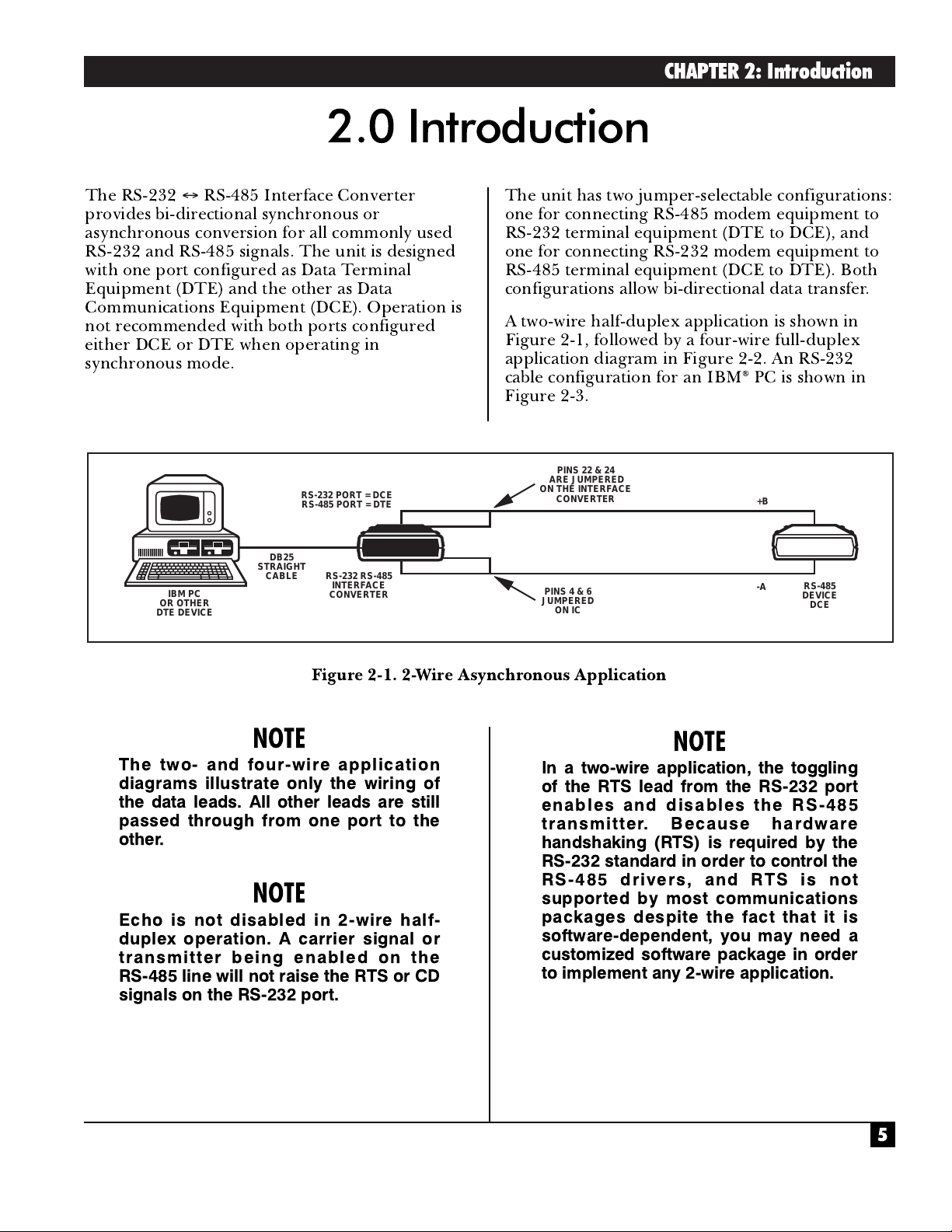
A two-wire half-duplex application is shown in
Figure 2-1, followed by a four-wire full-duplex
application diagram in Figure 2-2. An RS-232
cable configuration for an IBM
®
PC is shown in
Figure 2-3.
2.0 Introduction
Figure 2-1. 2-Wire Asynchronous Application
NOTE
The two- and four-wire application
diagrams illustrate only the wiring of
the data leads. All other leads are still
passed through from one port to the
other.
NOTE
Echo is not disabled in 2-wire half-
duplex operation. A carrier signal or
transmitter being enabled on the
RS-485 line will not raise the RTS or CD
signals on the RS-232 port.
NOTE
In a two-wire application, the toggling
of the RTS lead from the RS-232 port
enables and disables the RS-485
transmitter. Because hardware
handshaking (RTS) is required by the
RS-232 standard in order to control the
RS-485 drivers, and RTS is not
supported by most communications
packages despite the fact that it is
software-dependent, you may need a
customized software package in order
to implement any 2-wire application.
RS-232 PORT = DCE
RS-485 PORT = DTE
DB25
IBM PC
OR OTHER
DTE DEVICE
STRAIGHT
CABLE
RS-232/RS-485
INTERFACE
CONVERTER
PINS 22 & 24
ARE JUMPERED
ON THE INTERFACE
CONVERTER
PINS 4 & 6
JUMPERED
ON IC
+B
-A
RS-485
DEVICE
DCE

RS-232
↔
RS-485 INTERFACE CONVERTER
6
There are three models of this interface converter:
•
IC485A-R2 —
an RS-232↔RS-485 interface
converter standalone unit for 115 VAC
operation.
•
IC485AE-R2 —
a standalone unit for
220 VAC operation.
•
IC485C-R2 —
a rackmounted printed-circuit
card.
The same Card is used for both 115 volts and
230 volts.
An Interface Converter Rack is also available. This
is a 19" rack capable of holding up to eight printed
circuit cards. It operates in either
115-VAC or 230-VAC applications. The rack
(RM060) has its own power supply, which is
switchable between 115- and 230-VAC operation.
Figure 2-2. 4-Wire Asynchronous Application.
Figure2-3. Cable Configuration for the IBM PC.
IBM PC
OR OTHER
DTE DEVICE
RS-232 PORT = DCE
RS-485 PORT = DTE
DB25
STRAIGHT
CABLE
RS-232/RS-485
INTERFACE
CONVERTER
22
4
24
6
19
(GROUND
OPTIONAL)
R+
R-
T+
T-
GND
TYPICAL CABLE
CONFIGURATION FOR IBM PC
(RS-232)
DB25 FEMALE DB25 MALE
2
3
IBM PC CONVERTER
7
4
5
6
8
20
DEPENDING ON THE
SOFTWARE IN YOUR PC,
THIS SETUP MAY BE
NECESSARY
2
3
7
4
5
NOTE: THIS CONVERTER
IS CONFIGURED AS
DCE (ON RS-232 PORT)
RS-485
DEVICE
DCE

CHAPTER 3: Installation
7
Follow the instructions in Sections 3.1 and 3.2
before installing the Converter.
3.1 Jumpers and Switches
The Interface Converter has eleven jumpers
(listed in Table 3-3) and one 8-position DIP switch
labeled S1. Switch S1 functions to iprovide
termination on the converter's RS-485 ports.
(Refer to Figure 3-1 for the position of Switch S1
on the printed-circuit board.) When the switch is
in the ON position, a 120-ohm resistor is installed
across the RS-485 pin carrying the particular
signal indicated in Table 3-1. Only two RS-485
devices on a network (usually the first and last
device connected on the bus) will have one of the
DIP switch's pins in the ON position. The rest of
the converters will have these pins set to OFF. Set
this DIP switch's pins to the configuration that
your device requires. See Table 3-1.
3.2 Select DTE/DCE Operation
The RS-232↔RS-485 Interface Converter has two
jumper-selectable configurations for selecting
DTE/DCE operation on each port. One is for
connecting RS-485 Data Communications
Equipment (DCE) to RS-232 Data Terminal
Equipment (DTE). The second configuration is for
connecting RS-232 DCE to RS-485 DTE. These
settings are determined by DIP shunt settings
located inside the unit on the printed circuit
board. To set the interfaces, refer to Figure 3-1 for
their location and then set the DIP shunts
according to Table 3-2.
3.0 Installation
Table 3-1. Switch S1.
DIP Switch Pin Signal Terminated by the Resistor
1 Data
2 Receive Timing
3 Send Timing
4 Terminal Timing
5 Data Mode
6 Terminal Ready
7 RTS/CTS
8 Receiver Ready
NOTE
Operating the converter with both ports
configured for either DCE or DTE
operation is not recommended and can
damage the converter.
3.3 Physical Installation
After you configure the Converter, follow these
steps to install it in your application.
1.
Attach the cable from the RS-485 device to the
37-pin female receptacle on the rear panel of
the interface converter case.
2.
Attach the cable from the RS-232 device to the
25-pin female receptacle on the rear panel of
the interface converter case.
3.
Plug the 4-pin power cord into the receptacle
on the rear panel of the case and plug the
power module into an AC outlet.

RS-232
↔
RS-485 INTERFACE CONVERTER
8
Figure 3-1. Component Layout.
RS-485
CONNECTOR
RS-485
INDICATORS
RACK POWER
CONNECTOR
AC POWER
CONNECTOR
XW1A XW2A XW3A XW4A XW4B XW5A XW5B
XW1B XW2B XW3B
DIP SHUNTS
RS-422
CONNECTOR
DIP SHUNTS
RS-232
CONNECTOR
S1
CR8 CR5 CR6 CR10 CR9 CR4 CR7
DSR CTS DATA
RS-422
INDICATORS
POWER DSR CTS DATA
RS-232
INDICATORS

CHAPTER 3: Installation
9
Table 3-2. DTE/DCE DIP Shunts Settings.
RS-485 PORT RS-232 PORT
To appear as Put a shunt in To appear as Put a shunt in
DTE XW1A DTE XW4A
XW2A XW5A
XW3A
DCE XW1B DCE XW4B
XW2B XW5B
XW3B

RS-232
↔
RS-485 INTERFACE CONVERTER
10
Table 3-3 contains definitions of all the jumpers
on the interface converter's printed-circuit board.
Table 3-3. Jumpers.
Jumper Function
W1, W2, W3 These 16-pin DIP shunts are used to select DTE/DCE for the RS-485 port.
Install each in the DTE or DCE position as desired.
W4, W5 These 16-pin DIP shunts are used to select DTE/DCE for the RS-232 port.
Install each in the DTE or DCE position as desired.
W6 Selects RTS/CTS loopback delay for the RS-485 port when W9 is in the B-C
position (RTS-CTS loopback) as follows:
A=0 msec B=10 msec C=50 msec
W7 Selects RTS/CTS loopback delay for the RS-232 port when W10 is in the
A-B position (RTS-CTS loopback) as follows:
A=0 msec B=10 msec C=50 msec
W8 Position B-C: RS-485 transmitters are always enabled. This position should be
selected for four-wire applications.
Position A-B: tri-state control line of the RS-485 transmitters is driven by the
RS-232 equipment's RTS/CTS circuit.
NOTE: When W8 is in the B-C position, it overrides W9 and W10.
W9 Select RTS/CTS signal source for the RS-485 port as follows:
Position A-B: RS-485 RTS/CTS signal is driven by the RS-232 CTS signal.
Position B-C: RS-485 RTS/CTS signal is driven by the RTS/CTS
loopback/delay circuit.
W10 Selects RTS/CTS signal source for the RS-232 port as follows:
Position A-B: RS-232 RTS/CTS signal is driven by the
RTS/CTS loopback/delay circuit.
Position B-C: RS-232 RTS/CTS signal is driven by the RS-485 CTS signal.
W11 Connects the DC power supply common to AC power ground. This is a
soldered jumper which is left open as a factory default. If you wish, you can
hardwire it to provide both signal and frame ground.

CHAPTER 3: Installation
11
3.4 Indicators
The interface converter is equipped with seven
LED indicators located on the front panel, that
indicate input signals, NOT output.
• Three indicators reflect conditions on the
RS-232 interface: DSR (Data Set Ready),
CTS (Clear To Send), and Data.
• Three indicators reflect conditions on the
RS-485 interface: DSR (Data Set ready), CTS
(Clear To Send), and Data.
• One indicator, located in the center of the front
panel, PWR (Power), indicates when power is
applied to the unit.
Figures 3-2 and 3-3 illustrate signal flow in DTE
and DCE configurations.
NOTE
Some LEDs may be lit when no input
signal is present. This is not a
malfunction but a floating state
condition at the input which causes the
output of that driver to indicate a
positive voltage condition.

RS-232
↔
RS-485 INTERFACE CONVERTER
12
Figure 3-2. Signal Flow Diagram A.

CHAPTER 3: Installation
13
Figure 3-3. Signal Flow Diagram B.

RS-232
↔
RS-485 INTERFACE CONVERTER
14
3.5 Interface Pinouts
Figures 3-4 and 3-5 show pinouts for the RS-232
and RS-485 interfaces.
Figure 3-4. RS-232C Interface.
Figure 3-5. RS-485 Interface.
1 SHIELD
2 SIGNALING RATE INDICATOR
3
4 SEND DATA (-A)
5 SEND TIMING (-A)
6 RECEIVE DATA (-A)
7 REQUEST TO SEND (-A)
8 RECEIVE TIMING (-A)
9 CLEAR TO SEND (-A)
10 LOCAL LOOPBACK
11 DATA MODE (-A)
12 TERMINAL READY (-A)
13 RECEIVER READY (-A)
14 REMOTE LOOPBACK
15 INCOMING CALL
16 SELECT FREQUENCY
17 TERMINAL TIMING
18 TEST MODE
19 SIGNAL GROUND
RECEIVE COMMON 20
21
(+B) SEND DATA 22
(+B) SEND TIMING 23
(+B) RECEIVE DATA 24
(+B) REQUEST TO SEND 25
(+B) RECEIVE TIMING 26
(+B) CLEAR TO SEND 27
TERMINAL IN SERVICE 28
(+B) DATA MODE 29
(+B) TERMINAL READY 30
(+B) RECEIVER READY 31
SELECT STANDBY 32
SIGNAL QUALITY 33
NEW SIGNAL 34
(+B) TERMINAL TIMING 35
STANDBY/INDICATOR 36
SEND COMMON 37
RS-232 Interface (Female)
SIGNAL
DESTINATION
PROTECTIVE GROUND
TRANSMITTED DATA
RECEIVED DATA
REQUEST TO SEND
CLEAR TO SEND
SIGNAL GROUND / COMMON RETURN
RECEIVED LINE SIGNAL DETECTOR
SECONDARY RECEIVED LINE SIGNAL INDICATOR
SECONDARY CLEAR TO SEND
DATA SET READY
+ VOLTAGE
NUMBER
- VOLTAGE
PIN
1
2
3
4
5
6
7
8
9
10
11
12
13
PIN
NUMBER
SECONDARY TRANSMITTED DATA
14
15
DCE TRANSMITTER SIGNAL ELEMENT TIMING
16
SECONDARY RECEIVED DATA
17
RECEIVER ELEMENT TIMING
18
19
SECONDARY REQUEST TO SEND
20
DATA TERMINAL READY
21
SIGNAL QUALITY DETECTOR
22
RING INDICATOR
23
DATA SIGNAL RATE SELECTOR
24
DTE TRANSMITTER SIGNAL ELEMENT TIMING
25
SIGNAL
DESTINATION

1000 Park Drive • Lawrence, PA 15055-1018 • 724-746-5500 • Fax 724-746-0746
©Copyright 1993. Black Box Corporation. All rights reserved.
 Loading...