

CUSTOMER
SUPPORT
INFORMATION
Order toll-free in the U.S. 24 hours, 7 A.M. Monday to midnight Friday: 877-877-BBOX
FREE technical support, 24 hours a day, 7 days a week: Call 724-746-5500 or fax 724-746-0746
Mail order: Black Box Corporation, 1000 Park Drive, Lawrence, PA 15055-1018
Web site: www.blackbox.com • E-mail: info@blackbox.com
NOVEMBER 1996
IC474C
IC475C
Async 232↔422/530 Card
Power
TD
RD
CD
Unit
A
TD
RD
CD
Unit
B

4
ASYNC 232↔422/530 CARD
FEDERAL COMMUNICATIONS COMMISSION
AND
INDUSTRY CANADA
RADIO FREQUENCY INTERFERENCE STATEMENTS
This equipment generates, uses, and can radiate radio frequency energy
and if not installed and used properly, that is, in strict accordance with the
manufacturer’s instructions, may cause interference to radio communication.
It has been tested and found to comply with the limits for a Class A
computing device in accordance with the specifications in Subpart J of
Part 15 of FCC rules, which are designed to provide reasonable protection
against such interference when the equipment is operated in a commercial
environment. Operation of this equipment in a residential area is likely to
cause interference, in which case the user at his own expense will be required
to take whatever measures may be necessary to correct the interference.
Changes or modifications not expressly approved by the party responsible
for compliance could void the user’s authority to operate the equipment.
This digital apparatus does not exceed the Class A limits for radio noise emission from
digital apparatus set out in the Radio Interference Regulation of Industry Canada.
Le présent appareil numérique n’émet pas de bruits radioélectriques dépassant les limites
applicables aux appareils numériques de la classe A prescrites dans le Règlement sur le
brouillage radioélectrique publié par Industrie Canada.
TRADEMARKS USED IN THIS MANUAL
AT&T is a registered trademark of AT&T.
Hayes is a registered trademark of Zoom Telephonics, Inc.
Any other trademarks mentioned in this manual are acknowledged to be the property
of the trademark owners.

5
ASYNC 232↔422/530 CARD
NORMAS OFICIALES MEXICANAS (NOM)
ELECTRICAL SAFETY STATEMENT
INSTRUCCIONES DE SEGURIDAD
1. Todas las instrucciones de seguridad y operación deberán ser leídas antes
de que el aparato eléctrico sea operado.
2. Las instrucciones de seguridad y operación deberán ser guardadas para
referencia futura.
3. Todas las advertencias en el aparato eléctrico y en sus instrucciones de
operación deben ser respetadas.
4. Todas las instrucciones de operación y uso deben ser seguidas.
5. El aparato eléctrico no deberá ser usado cerca del agua—por ejemplo,
cerca de la tina de baño, lavabo, sótano mojado o cerca de una alberca,
etc..
6. El aparato eléctrico debe ser usado únicamente con carritos o pedestales
que sean recomendados por el fabricante.
7. El parato eléctrico debe ser montado a la pared o al techo sólo como sea
recomendado por el fabricante.
8. Servicio—El usuario no debe intentar dar servicio al equipo eléctrico más
allá a lo descrito en las instrucciones de operación. Todo otro servicio
deberá ser referido a personal de servicio calificado.
9. El aparato eléctrico debe ser situado de tal manera que su posición no
interfiera su uso. La colocación del aparato eléctrico sobre una cama,
sofá, alfombra o superficie similar puede bloquea la ventilación, no se
debe colocar en libreros o gabinetes que impidan el flujo de aire por los
orificios de ventilación.
10. El equipo eléctrico deber ser situado fuera del alcance de fuentes de
calor como radiadores, registros de calor, estufas u otros aparatos
(incluyendo amplificadores) que producen calor.

6
ASYNC 232↔422/530 CARD
11. El aparato eléctrico deberá ser connectado a una fuente de poder sólo
del tipo descrito en el instructivo de operación, o como se indique en el
aparato.
12. Precaución debe ser tomada de tal manera que la tierra fisica y la
polarización del equipo no sea eliminada.
13. Los cables de la fuente de poder deben ser guiados de tal manera que no
sean pisados ni pellizcados por objetos colocados sobre o contra ellos,
poniendo particular atención a los contactos y receptáculos donde salen
del aparato.
14. El equio eléctrico debe ser limpiado únicamente de acuerdo a las
recomendaciones del fabricante.
15. En caso de existir, una antena externa deberá ser localizada lejos de las
lineas de energia.
16. El cable de corriente deberá ser desconectado del cuando el equipo no
sea usado por un largo periodo de tiempo.
17. Cuidado debe ser tomado de tal manera que objectos liquidos no sean
derramados sobre la cubierta u orificios de ventilación.
18. Servicio por personal calificado deberá ser provisto cuando:
A: El cable de poder o el contacto ha sido dañado; u
B: Objectos han caído o líquido ha sido derramado dentro del
aparato; o
C: El aparato ha sido expuesto a la lluvia; o
D: El aparato parece no operar normalmente o muestra un cambio en su
desempeño; o
E: El aparato ha sido tirado o su cubierta ha sido dañada.

7
ASYNC 232↔422/530 CARD
Contents
1. Specifications.....................................................................................................5
2. Introduction ......................................................................................................6
3. Configuration ....................................................................................................7
3.1 Jumper Locations and Orientation ...........................................................8
3.2 Setting the Configuration Straps...............................................................9
3.3 Rear-Card Configuration ...........................................................................9
3.3.1 RJ-11/RJ-45 Jumper Settings .........................................................10
3.3.2 RJ-45/RJ-45 Jumper Settings .........................................................13
4. Installation.......................................................................................................16
4.1 The MicroRack Chassis ............................................................................16
4.2 Installing the Async 232↔422/530 Card in the Chassis ........................18
4.3 Wiring Up the Async 232↔422/530 Card..............................................19
4.3.1 RS-232 Connection.........................................................................19
4.3.2 Twisted-Pair Connection................................................................19
4.3.3 Point-to-Point Twisted-Pair Connection .......................................20
5. Operation ........................................................................................................22
5.1 LED Status Monitors ................................................................................22
5.2 Power-Up ..................................................................................................23
Appendix A. Cable Recommendations.............................................................24
Appendix B. Interface Settings .........................................................................25
Appendix C. PC Adapters..................................................................................26

8
Data Rate 0 to 19.2 Kbps
Connectors IC474C: (2) RJ-11; IC475C: (2) RJ-45
Transmission Format Asynchronous
Transmission Mode Full duplex, 4-wire
Transmission Line 4-wire, unconditioned line
(2 twisted pairs)
Transmit Level 0 dBm
Control Signal DCE Mode: CTS (Pin 8) turns ON
immediately after the terminal raises
RTS (Pin 9); DSR (Pin 2) turns ON
immediately after the rack has power;
CD (Pin 3) is constantly ON if RXC is
present, normal if RXC is absent
Surge Protection 600W power dissipation at 1 mS
MTBF 239,906 hours
MTTR 1 hour
Operating Temperature 32° to 122°F (0° to 50°C)
Humidity 10 to 95%, noncondensing
Altitude Up to 15,000 feet (4570 m)
Power Provided by power supply in rack
Size 3.1"H x 0.95"W x 5.4"L
(7.9 x 2.4 x 13.7 cm)
CHAPTER 1: Specifications
1. Specifications

9
ASYNC 232↔422/530 CARD
The Async 232↔422/530 Card is a dual rack card incorporating two
converters. The converters let computers, terminals, and modems using the
RS-232 interface communicate with devices using RS-422 balanced electrical
signals. Both units operate full duplex at data rates to 19.2 Kbps over 2 twisted
pairs. The Async 232↔422/530 Card features 13 easy-to-read front-panel
LEDs, which monitor the status of data transmission. As an added feature,
a set of easily accessible configuration straps allows the user to control the
function of the carrier-detect LEDs.
The Async 232↔422/530 Card uses the latest surface-mount technology
for high-quality short-range modem performance in a convenient rack card.
Filling one function card slot on the MicroRack (RM202, RM204, RM208, and
RM216) chassis, the Async 232↔422/530 Card is available with RJ-11 or RJ-45
rear interface cards.
2. Introduction
10
CHAPTER 3: Configuration
This section describes the location and orientation of the Async
232↔422/530 Card’s configuration jumpers, provides detailed instructions
on setting each jumper, and describes the settings for each of the rear
connection cards.
The Async 232↔422/530 Card uses two jumpers that allow configuration to a
wide range of asynchronous applications. These jumpers are accessible when
the card is slid out of the rack chassis. Once the hardware is configured, the
Async 232↔422/530 Card is designed to operate transparently, without need
for frequent re-configuration: Just set it and forget it.
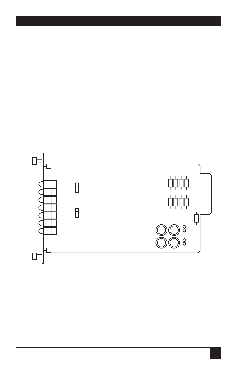
Figure 3-1. Location of configuration jumpers
on the Async 232↔422/530 Card.
Unit A
JP1
1
2
3
1
2
3
Unit B
JP2
3. Configuration
11
ASYNC 232↔422/530 CARD
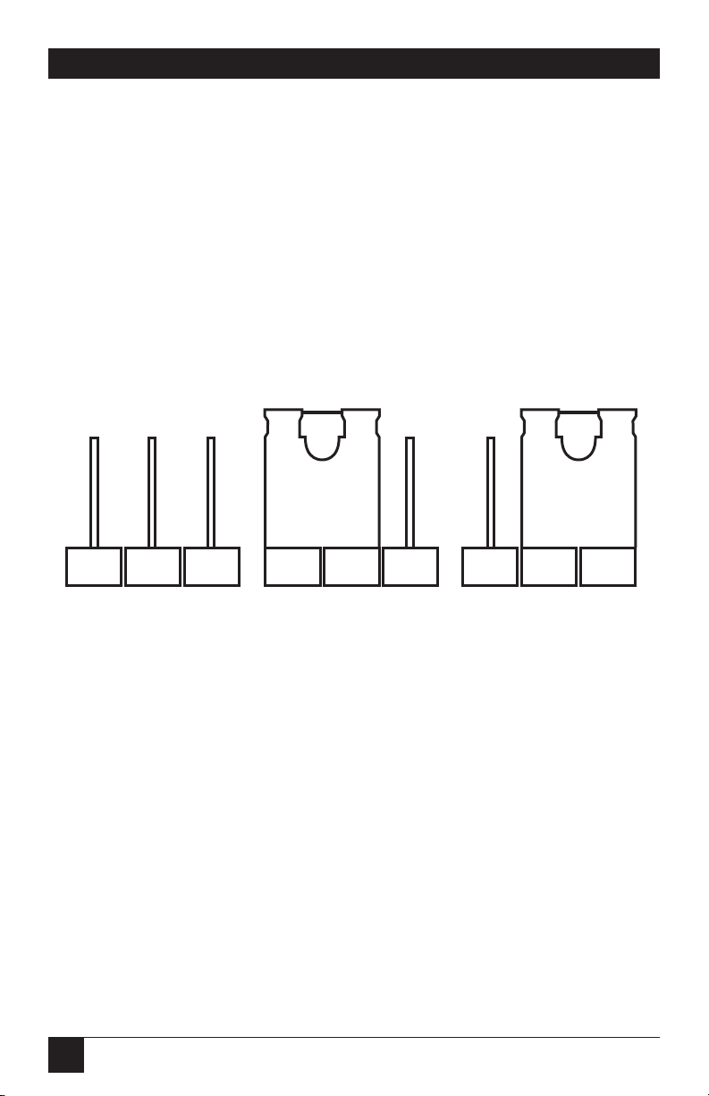
3.1 Jumper Locations and Orientation
The configuration jumpers on the Async 232↔422/530 Card and the
rear interface card allow you to configure the function of both front-panel
“Carrier Detect” LEDs, as well as the rear interface card CD signal. Figure 3-2
shows the orientation of these jumpers. Notice that each jumper can be either
on pegs 1 and 2, or on pegs 2 and 3. Note: Pin 1 is always located on the top
or left side of the jumper set.
Figure 3-2. Orientation of interface card straps.
123 123 123

12
CHAPTER 3: Configuration
3.2 Setting the Configuration Straps
The Async 232↔422/530 Card contains two sets of configuration jumpers,
which allow you to set the function of both front-panel “Carrier Detect” LEDs
and the CD signal exiting the rear interface card in the rack. Since the Async
232↔422/530 Card contains two converters, each unit can be configured
separately.
Both “Carrier Detect” straps can be set to “Normal” or “Always on.” When
operating normally, the “CD” LED will blink to indicate the presence or
absence of the carrier. When set to “Always on,” the CD LED will always
indicate that the carrier is ON. The table below summarizes the jumper
settings. The default position is “Always on.”
Interface Card Jumper Summary Table
Jumper Function Position 1 & 2 Position 2 & 3
JP1—Unit A Carrier Detect “Always ON” “Normal”
JP2—Unit B Carrier Detect “Always ON” “Normal”
3.3 Rear-Card Configuration
The Async 232↔422/530 Card has two interface-card options: the IC474C
(which comes equipped with two RJ-11 ports and two RJ-45 ports) and the
IC475C (which comes equipped with four RJ-45 ports). Figure 3-3 shows
these options.

13
ASYNC 232↔422/530 CARD
Figure 3-3. Async 232↔422/530 Card rear interface cards.
Before installation, you should examine the rear card you have selected and
make sure that it is suitable for your application. Each rear card is configured
by setting straps on the PC board.
3.3.1 RJ-11/RJ-45 J
UMPERSETTINGS
Figure 3-4 shows the jumper locations for the IC474C rear card. These
jumpers determine various grounding characteristics for the RS-232 and
twisted-pair lines.
RJ-11
RJ-11
RJ-45
RJ-45
RJ-45
RJ-45
RJ-45
RJ-45
(8-pin)
(8-pin)
(10-pin)
(10-pin)
(6-pin)
(6-pin)
(10-pin)
(10-pin)
IC474C IC475C

14
CHAPTER 3: Configuration
Figure 3-4. RJ-11/RJ-45 jumper locations.
Table 3-1 (on the next page) provides a summary of jumper functions for
both of the rear cards. The next page describes each jumper’s function.
JB2
JB4
JB6
JB7
Terminal
(RS-232)
RJ-11 (Unit A)
RJ-11 (Unit B)
Converter
twisted pair
(RS-422)
RJ-45 (Unit A)
RJ-45 (Unit B)
JB5
1
2
3
1
2
3
1
2
3
3
1
2
123

15
ASYNC 232↔422/530 CARD
Table 3-1. Summary of jumper settings
Interface Card Jumper Summary
Jumper Function Position 1 & 2 Position 2 & 3
JB2 Line A Shield Connected No Shield*
JB4 Line B Shield Connected No Shield*
JB5 SGND & FRGND Connected Open*
JB6 DTE A DSR* Connected N/A
JB7 DTE B DSR* Connected N/A
*Indicates factory default
Line Shield (JB2 and JB4)
This jumper pertains to the line interface. In the connected position, the
jumper links RJ-11 pins 1 and 6 to frame ground and the rear panel. These
pins can be used as connections for the twisted-pair cable shield. In position
2 and 3, pins 1 and 6 (or RJ-45 pins 2 and 7) are disconnected from frame
ground.
JB2 and JB4
Position 1 & 2 = Line Shield A and B Connected to Frame Ground
Position 2 & 3 = No Shield

16
CHAPTER 3: Configuration
DTE as DSR or RI (JB6 and JB7)
Because this rear card is designed to function in more applications than the
Async 232↔422/530 Card, this jumper must be installed only in one position.
Place the jumper across pins 1 and 2 so that the terminal (DTE) sees DSR as
high when the rack is powered. The other positions, across pins 2 and 3, are
for Ring Indicate as defined by EIA/TIA-561. The RI function is irrelevant
(and on the Async 232↔422/530 Card is also disconnected) and can cause
improper operation if the jumper is installed incorrectly.
JB6 and JB7
Position 1 & 2 = DSR
Position 2 & 3 = N/A (Do not use.)
SGND and FRGND (JB5)
In the connected position, this jumper links RJ-45 pin 5 (Signal Ground) and
frame ground through a 100-ohm, 1⁄2
-watt resistor. In the open position, pin 1
is disconnected from frame ground.
JB5
Position 1 & 2 = SGND (Pin 5) and FRGND Connected
Position 2 & 3 = SGND (Pin 5) and FRGND Not Connected
3.3.2 RJ-45/RJ-45 J
UMPERSETTINGS
Figure 3-5 shows the strap locations for the IC475C rear card. These jumpers
determine grounding characteristics for the RS-232 and twisted-pair converter
lines.

17
ASYNC 232↔422/530 CARD
Figure 3-5. RJ-45/RJ-45 jumper locations.
Refer to Table 3-1 for a summary of the jumper functions.
3
1
2
3
1
2
3
1
2
3
1
2
123
JB2
JB4
JB6
JB7
Terminal
RJ-45 (Unit A)
RJ-45 (Unit B)
Converter
twisted pair
RJ-45 (Unit A)
RJ-45 (Unit B)
JB5

18
CHAPTER 3: Configuration
Line Shield (JB2 and JB4)
This jumper pertains to the line interface. In the connected position, the
jumper links RJ-45 pins 2 and 7 to frame ground and the rear panel. These
pins can be used as connections for the twisted-pair cable shield. In position
2 and 3, pins 2 and 7 are disconnected from frame ground.
JB2 and JB4
Position 1 & 2 = Line Shield A and B Connected to Frame Ground
Position 2 & 3 = No Shield
DTE as DSR or RI (JB6 and JB7)
Because this rear card is designed to function in more applications than the
Async 232↔422/530 Card, this jumper must be installed only in one position.
Place the jumper across pins 1 and 2 so that the terminal (DTE) sees DSR as
high when the rack is powered. The other positions, across pins 2 and 3, are
for Ring Indicate as defined by EIA/TIA-561. The RI function is irrelevant
(and on the Async 232↔422/530 Card is also disconnected) and can cause
improper operation if the jumper is installed incorrectly.
JB6 and JB7
Position 1 & 2 = DSR
Position 2 & 3 = N/A (Do not use.)
SGND and FRGND (JB5)
In the connected position, this jumper links RJ-45 pin 5 (Signal Ground) and
frame ground through a 100-ohm, 1⁄2 watt resistor. In the open position, pin 1
is disconnected from frame ground.
JB5
Position 1 & 2 = SGND (Pin 5) and FRGND Connected
Position 2 & 3 = SGND (Pin 5) and FRGND Not Connected

19
ASYNC 232↔422/530 CARD
This chapter describes the functions of the MicroRacks, tells how to install
front and rear Async 232↔422/530 Cards in the chassis, and provides
diagrams for wiring the interface connections correctly.
4.1 The MicroRack Chassis
The MicroRack 16 has sixteen short-range modem card slots, plus its own
power supply. Measuring only 3.5 inches high, the MicroRack is designed to
occupy only 2U in a 19-inch rack. Sturdy front handles allow the MicroRack
16 to be extracted and transported conveniently.
Figure 4-1. The MicroRack 16 with power supply.
The power supply used in the MicroRack 16 uses the same mid-plane
architecture as the modem cards. The front card of the power supply slides
in from the front, and the rear card slides in from the rear. They plug into
one another in the middle of the rack. The front card is then secured by
thumbscrews and the rear card by conventional metal screws.
ON
OFF
Power
MicroRack System
AC Power Supply
4. Installation

20
CHAPTER 4: Installation
WARNING!
There are no user-serviceable parts in the power-supply section of the
MicroRack 16. Voltage setting changes and fuse replacement should
only be performed by qualified service personnel.
Switching the Power Supply On and Off
The power-supply on/off switch is located on the front panel. When the
MicroRack is plugged in and switched on, a red front-panel LED will glow.
Since the MicroRack is a hot-swappable rack, it is not necessary for any cards
to be installed before switching on the power supply. The power supply may
be switched off at any time without harming the installed cards.
Replacing the Power-Supply Fuse
The rack chassis power supply uses a 400-mA fuse for 120-VAC circuits, and a
200-mA fuse for 240-VAC circuits. The fuse compartment is located just below
the AC socket on the rear card. To replace the fuse:
1) Turn the power switch off and remove the power cord.
2) Using a small screwdriver, pop the compartment open (it will slide open
like a drawer). Depending upon the exact part used, the drawer may slide
completely out of the fuse holder, or it may stop partway out.
3) Note that there are two fuses in the drawer. The front fuse is the spare,
and the rear fuse is the “active” fuse.
4) If the active fuse appears to be blown, remove it from the clips and
replace it with the spare from the front compartment. Note the size
and rating of the blown fuse before discarding it.
5) Buy a replacement fuse at an electronics store.
WARNING!
For continued protection against the risk of fire, replace only with the
same type and rating of fuse.

21
ASYNC 232↔422/530 CARD
Switching the Power Supply Between 120 and 240 Volts
Although the MicroRack 16 is shipped from the factory with a customerspecified power-supply configuration, you can change the configuration
yourself. Follow the steps at the top of the next page to switch the
configuration of the power supply between 120 and 240 VAC:
1) Remove the front power-supply card and locate the two-position switch
near the back of the card. Slide the switch to the desired voltage. (Note:
The actual values on the switch may be “110/220” or “115/230.”)
2) Replace the existing fuse with one of the correct value.
3) Replace the power-supply cord, if necessary.
4.2 Installing the Async 232↔422/530 Card in the Chassis
The Async 232↔422/530 Card is made up of a front card and a rear card.
The two cards meet inside the rack chassis and plug into each other by way
of mating 50-pin card edge connectors. Use the following steps as a guideline
for installing each Async 232↔422/530 Card into the rack chassis.
1) Slide the rear card into the back of the chassis along the metal
rails provided.
2) Secure the rear card using the metal screws provided.
3) Slide the Function card into the front of the chassis. It should
meet the rear card when it’s almost all the way into the chassis.
4) Push the front card gently into the card-edge receptacle
of the rear card. It should click into place.
5) Secure the front card using the thumbscrews.
NOTE
Since the MicroRack chassis allows hot-swapping of cards, it is not
necessary to power down the rack when you install or remove an Async
232↔422/530 Card.

22
4.3 Wiring Up the Async 232↔422/530 Card
Each of the rear interface cards is compatible with the Async 232↔422/530
Card and has four RJ ports. The two upper ports are either RJ-11 or RJ-45
jacks, depending on the card you select.
4.3.1 RS-232 C
ONNECTION
The RS-232 ports are always the lower ports on the interface card. The 10-pin
RJ-45s are based on the EIA/TIA-561 Standard. For specific interface pinouts,
refer to the diagrams in Appendix B.
NOTE
European “CE” recommendations require that any terminal cable
connected to the Async 232↔422/530 Card must be shielded cable, and
the outer shield must be 360° bonded—at both ends—to a metal or
metalized backshell.
The Async 232↔422/530 Card is wired as a DCE (Data Communications
Equipment). Therefore, it wants to connect to a DTE (Data Termination
Equipment). If your RS-232 output device is a DTE, use a straight-through
cable to connect to the Async 232↔422/530 Card. If your RS-232 output
device is DCE, call your supplier for specific installation instructions.
4.3.2 T
WISTED-PAIRCONNECTION
The Async 232↔422/530 Card operates full duplex over two twisted pairs.
In all applications, the twisted-pair wire must be 26 AWG or thicker,
unconditioned, dry, metallic wire. Both shielded and unshielded wire
yield favorable results.
NOTE
The Async 232↔422/530 Card can only be installed on private twistedpair cable. Dialup analog circuits, such as those used with a standard
Hayes
®
compatible modem, are not acceptable. For more information
about acceptable wire grades, refer to Appendix A.
CHAPTER 4: Installation

23
ASYNC 232↔422/530 CARD
4.3.3 P
OINT-TO-POINTTWISTED-PAIRCONNECTION
The six-position RJ-11 and eight-position RJ-45 jack options for the Async
232↔422/530 Card (always the two upper jacks on the rear interface card)
are prewired for a standard telco wiring environment. Connection of a 4-wire
twisted-pair circuit between two or more Async 232↔422/530 Cards requires
a crossover cable. Refer to the next page for more information.
CROSSOVER CABLES
RJ-11
Signal Pin No. Color
‡
Color Pin No. Signal
GND
†
1 Blue ................White 6 GND
†
RCVB 2 Yellow .............Red 4 XMTB
XMTA 3 Green .............Black 5 RCVA
XMTB 4 Red .................Yellow 2 RCVB
RCVA 5 Black...............Green 3 XMTA
GND
†
6 White ..............Blue 1 GND
†
RJ-45
Signal Pin No. Color
‡
Color Pin No. Signal
GND
†
2 Orange ...........Brown 7 GND
†
RCVB 3 Black...............Green 5 XMTB
XMTA 4 Red .................Yellow 6 RCVA
XMTB 5 Green .............Black 3 RCVB
RCVA 6 Yellow .............Red 4 XMTA
GND
†
7 Brown .............Orange 2 GND
†
IMPORTANT!
In the pinouts above, “A” means positive and “B” means negative.
†
Connection to ground is optional
‡
Standard color codes—yours may be different

24
CHAPTER 4: Installation
Figure 4-2. AT&T®standard modular color codes.
DCE-DTE Connection:
Two lower RS-232 jacks on rear interface card
1. N/A
2. DSR
3. CD
4. N/A
5. SG
6. RD
7. TD
8. CTS
9. RTS
10. N/A
1 - Blue
2 - Yellow
3 - Green
4 - Red
5 - Black
6 - White
1 - Blue
2 - Orange
3 - Black
4 - Red
5 - Green
6 - Yellow
7 - Brown
8 - Slate
RJ-11
RJ-45/8
1 - n/a
2 - Blue
3 - Orange
4 - Black
5 - Red
6 - Green
7 - Yellow
8 - Brown
9 - Slate
10 - n/a
RJ-45/10

25
ASYNC 232↔422/530 CARD
Once you have configured each Async 232↔422/530 Card and connected
the cables, you are ready to operate the units.
5.1 LED Status Monitors
The Async 232↔422/530 Card features 13 front-panel LEDs that indicate
the condition of the modem and communication link. Figure 5-1 shows
the positions of the LEDs.
Figure 5-1. The Async 232↔422/530 Card front panel,
showing LED positions.
UNIT
A
UNIT
B
Power
RD
CD
TD
RD
CD
TD
5. Operation

26
• The green “PWR” LED glows when power is being applied to the
modem card through its mid-plane chassis connection.
• The green “TD” and “RD” LEDs blink to show positive state data
activity. The red “TD” and “RD” indicators blink to show negative state
data activity. A solid red light indicates an idle state.
• If your carrier-detect strap is configured as “Always On,” the “CD” LED
will always be green. If the carrier-detect strap is set to “Normal,” the
green LED lights when the carrier is on; the red LED lights when the
carrier is off.
5.2 Power-Up
There is no power switch on the Async 232↔422/530 Card: Power is
automatically applied to the Async 232↔422/530 Card when its card-edge
connector touches the chassis’s mid-plane socket, or when the chassis’s power
is turned on.
NOTE
The Async 232↔422/530 Card is a hot-swappable card—it will not be
damaged by plugging it in or removing it while the rack is powered up.
CHAPTER 5: Operation

27
ASYNC 232↔422/530 CARD
The Card operates at frequencies of 20 KHz or less and has been performance-tested using twisted-pair cable with the following characteristics:
Wire Gauge Capacitance Resistance
19 AWG 83nf/mi or 15.72 pf/ft. 0.0163 ohms/ft.
22 AWG 83nf/mi or 15.72 pf/ft. 0.0326 ohms/ft.
24 AWG 83nf/mi or 15.72 pf/ft. 0.05165 ohms/ft.
The following data rate/distance results were obtained during bench tests
using or simulating cable with the characteristics listed above:
Data Rate (bps) Gauge (AWG)/Distance (Mi)
19 22 24
38.4—115.2 5.6 3.1 2.5
0—19.2 9.4 5.6 4.4
For optimum performance from your Async 232↔422/530 Card, keep the
following guidelines in mind:
• Always use twisted-pair wire—this is not an option.
• Use twisted-pair wire with a capacitance of 20 pf/ft. or less.
• Avoid twisted-pair wire thinner than 26 AWG (in other words, avoid
higher AWG numbers than 26).
• Use of twisted pair with a resistance greater than the above specifications
may cause a reduction in maximum distance obtainable. Functionality
should not be affected.
• Many different environmental factors can affect the maximum distances
obtainable at a particular site. Use the data rate/distance table as a
general guideline only.
Appendix A. Cable Recommendations

28
APPENDIX B: Interface Settings
RS-232 Modular Interface: 10-Wire RJ-45
Contact Number Circuit Description
1 N/A Not Used
2 107 DSR
3 109 Received Line Signal Indicator (CD)
4 108/2 DTE Ready (DTR)
5 102 Signal Common
6 104 Received Data
7 103 Transmitted Data
8 106 Clear to Send
9 105/133 Request to Send/Ready for Receiving
10 N/A Not Used
Pins 2–9 conform to the EIA/TIA-561 eight-position non-synchronous interface
standard.
RJ-11
RJ-11
RJ-45
RJ-45
RJ-45
RJ-45
RJ-45
RJ-45
(8
(8
(1
(1
(6-pin)
(6-pin)
(10-pin)
(10-pin)
Appendix B. Interface Settings
For all modular jacks
(6-, 8-, or 10-position):
Pin 1 is always toward the
bottom when the rear card is
oriented correctly in the slot.

29
ASYNC 232↔422/530 CARD
DB25 RJ-45 (8-Pin)
DSR 6- - - - - - - - - - - - - - - 1
CD 8- - - - - - - - - - - - - - - 2
DTR 20- - - - - - - - - - - - - - - 3
Signal Ground 7 - - - - - - - - - - - - - - - 4
RD 3- - - - - - - - - - - - - - - 5
TD 2- - - - - - - - - - - - - - - 6
CTS 5- - - - - - - - - - - - - - - 7
RTS 4- - - - - - - - - - - - - - - 8
DB9 RJ-45 (8-Pin)
DSR 6- - - - - - - - - - - - - - - 1
CD 1- - - - - - - - - - - - - - - 2
DTR 4 - - - - - - - - - - - - - - - 3
Signal Ground 5 - - - - - - - - - - - - - - - 4
RD 2- - - - - - - - - - - - - - - 5
TD 3- - - - - - - - - - - - - - - 6
CTS 8- - - - - - - - - - - - - - - 7
RTS 7- - - - - - - - - - - - - - - 8
Appendix C. PC Adapters

1000 Park Drive • Lawrence, PA 15055-1018 • 724-746-5500 • Fax 724-746-0746
© Copyright 1996. Black Box Corporation. All rights reserved.
 Loading...