

Page 1
CUSTOMER
SUPPORT
INFORMATION
Order toll-free in the U.S.: Call 877-877-BBOX (outside U.S. call 724-746-5500)
FREE technical support 24 hours a day, 7 days a week: Call 724-746-5500 or fax 724-746-0746
Mailing address: Black Box Corporation, 1000 Park Drive, Lawrence, PA 15055-1018
Web site: www.blackbox.com • E-mail: [email protected]
DECEMBER 2002
IC445A
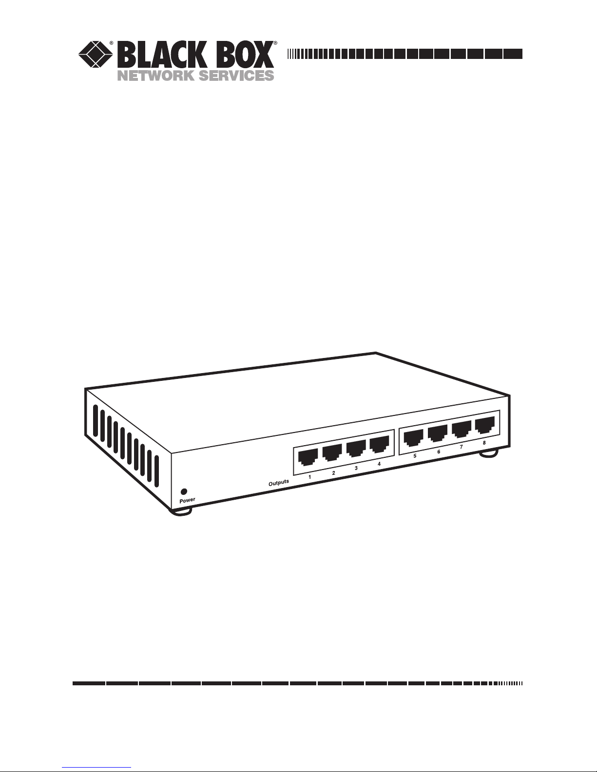
Video CCTV-A/V Hub
Page 2

1
FCC/IC RFI STATEMENTS, EU DECLARATION OF CONFORMITY
FEDERAL COMMUNICATIONS COMMISSION AND INDUSTRY CANADA
RADIO-FREQUENCY INTERFERENCE STATEMENTS
This equipment generates, uses, and can radiate radio-frequency energy, and if not
installed and used properly, that is, in strict accordance with the manufacturer’s
instructions, may cause interference to radio communication. It has been tested
and found to comply with the limits for a Class A computing device in accordance
with the specifications in Subpart B of Part 15 of FCC rules, which are designed to
provide reasonable protection against such interference when the equipment is
operated in a commercial environment. Operation of this equipment in a
residential area is likely to cause interference, in which case the user at his own
expense will be required to take whatever measures may be necessary to correct the
interference.
Changes or modifications not expressly approved by the party responsible for
compliance could void the user’s authority to operate the equipment.
This digital apparatus does not exceed the Class A limits for radio noise emission from digital
apparatus set out in the Radio Interference Regulation of Industry Canada.
Le présent appareil numérique n’émet pas de bruits radioélectriques dépassant les limites
applicables aux appareils numériques de la classe A prescrites dans le Règlement sur le
brouillage radioélectrique publié par Industrie Canada.
EUROPEAN UNION DECLARATION OF CONFORMITY
The manufacturer declares that this product meets the requirements of
EU Directive 89/336/EEC by complying with EN 55022.
Page 3

2
VIDEO CCTV-A/V HUB
NORMAS OFICIALES MEXICANAS (NOM)
ELECTRICAL SAFETY STATEMENT
INSTRUCCIONES DE SEGURIDAD
1. Todas las instrucciones de seguridad y operación deberán ser leídas antes de
que el aparato eléctrico sea operado.
2. Las instrucciones de seguridad y operación deberán ser guardadas para
referencia futura.
3. Todas las advertencias en el aparato eléctrico y en sus instrucciones de
operación deben ser respetadas.
4. Todas las instrucciones de operación y uso deben ser seguidas.
5. El aparato eléctrico no deberá ser usado cerca del agua—por ejemplo, cerca
de la tina de baño, lavabo, sótano mojado o cerca de una alberca, etc..
6. El aparato eléctrico debe ser usado únicamente con carritos o pedestales que
sean recomendados por el fabricante.
7. El aparato eléctrico debe ser montado a la pared o al techo sólo como sea
recomendado por el fabricante.
8. Servicio—El usuario no debe intentar dar servicio al equipo eléctrico más allá
a lo descrito en las instrucciones de operación. Todo otro servicio deberá ser
referido a personal de servicio calificado.
9. El aparato eléctrico debe ser situado de tal manera que su posición no
interfiera su uso. La colocación del aparato eléctrico sobre una cama, sofá,
alfombra o superficie similar puede bloquea la ventilación, no se debe colocar
en libreros o gabinetes que impidan el flujo de aire por los orificios de
ventilación.
10. El equipo eléctrico deber ser situado fuera del alcance de fuentes de calor
como radiadores, registros de calor, estufas u otros aparatos (incluyendo
amplificadores) que producen calor.
11. El aparato eléctrico deberá ser connectado a una fuente de poder sólo del
tipo descrito en el instructivo de operación, o como se indique en el aparato.
Page 4

3
NOM STATEMENT, TRADEMARKS
12. Precaución debe ser tomada de tal manera que la tierra fisica y la polarización
del equipo no sea eliminada.
13. Los cables de la fuente de poder deben ser guiados de tal manera que no
sean pisados ni pellizcados por objetos colocados sobre o contra ellos,
poniendo particular atención a los contactos y receptáculos donde salen del
aparato.
14. El equipo eléctrico debe ser limpiado únicamente de acuerdo a las
recomendaciones del fabricante.
15. En caso de existir, una antena externa deberá ser localizada lejos de las lineas
de energia.
16. El cable de corriente deberá ser desconectado del cuando el equipo no sea
usado por un largo periodo de tiempo.
17. Cuidado debe ser tomado de tal manera que objectos liquidos no sean
derramados sobre la cubierta u orificios de ventilación.
18. Servicio por personal calificado deberá ser provisto cuando:
A: El cable de poder o el contacto ha sido dañado; u
B: Objectos han caído o líquido ha sido derramado dentro del aparato; o
C: El aparato ha sido expuesto a la lluvia; o
D: El aparato parece no operar normalmente o muestra un cambio en su
desempeño; o
E: El aparato ha sido tirado o su cubierta ha sido dañada.
TRADEMARKS USED IN THIS MANUAL
BLACK BOX and the logo are registered trademarks of Black Box
Corporation.
Any other trademarks mentioned in this manual are acknowledged to be the property of the
trademark owners.
Page 5

4
VIDEO CCTV-A/V HUB
Contents
Chapter Page
1. Specifications ............................................................................................. 5
2. Introduction ............................................................................................... 8
3. Installation .................................................................................................. 9
3.1 Installing a Single Hub ....................................................................... 9
3.2 Typical Applications ......................................................................... 14
3.3 Installing a Hub in a Daisychain or Cascade ................................... 15
4. Troubleshooting ...................................................................................... 17
4.1 Common Concerns ........................................................................... 17
4.2 Calling Black Box .............................................................................. 18
4.3 Shipping and Packaging ................................................................... 18
Page 6

5
CHAPTER 1: Specifications
1. Specifications
Cable Required: Between hub and baluns: Unshielded twisted pair (UTP):
Construction standard: Category 3 or higher;
Gauge: 24 AWG or lower;
Core: Solid;
Termination: RJ-45 plugs;
Pairs: Number needed depends on baluns (see balun
manuals); cable with four pairs (eight wires) can support
all balun models;
Impedance: 100 ohms at 1 MHz;
Maximum capacitance: 20 pF/ft. (6.1 pF/m);
Maximum attenuation: 6.6 dB/1000 ft. (2 dB/km) at
1 MHz;
To attached devices: Depends on baluns (see balun
manuals)
Compliance: CE (EN 55022); FCC Class A, IC Class/classe A;
CISPR Pub. 22 Class B
Video Support: S-Video; NTSC or PAL composite (baseband) video
Transmission: Transparent to users (automatic, no delay)
Required Source
Impedance: Video OUT: 75 ohms;
Audio OUT (if any): 600 ohms maximum
Required Destination
Impedance: Video IN: 75 ohms;
Audio IN (if any): 600 ohms minimum
Hub Impedance: Video IN and video OUT: 100 ohms balanced;
Audio IN: 10 kiloohms minimum balanced;
Audio OUT: 600 ohms balanced
Bandwidth (3 dB): Video: DC to 8 MHz;
Audio: 50 Hz to 16 kHz
Maximum
Differential
Input and Output: Video: 0.55 volts peak-to-peak;
Audio: 0.5 volts peak-to-peak
Page 7

6
VIDEO CCTV-A/V HUB
Differential
Insertion Loss: Video: 0 dB maximum at 4 MHz;
Audio: 1 dB maximum at 1 MHz
Video Return Loss: 24 dB minimum
Common-Mode
Rejection: Input balanced, output unbalanced;
Video: Greater than 40 dB over the frequency range;
Audio: Greater than 60 dB over the frequency range
Crosstalk Immunity: 60 dB minimum over the frequency range
Maximum
Distance: Total end to end, from source device through hub(s) to
destination device, over good CAT5 cable (assuming A/V
source outputs signal at normal strength):
Black & white composite video: 2500 ft. (762 m);
Color composite video: 2200 ft. (671 m);
S-Video: 1000 ft. (305 m)
Indicator: (1) Front-mounted power LED
Connectors: (10) RJ-45 female:
(1) rear-mounted for input;
(1) rear-mounted for looping output;
(8) front-mounted for regular output;
(1) Rear-mounted 5-pin DIN female power inlet
RJ-45 Pins Used: All: Pin 1 is audio 1 ring, Pin 2 is audio 1 tip, Pin 3 is audio 2
ring, Pin 4 is video 2 ring, Pin 5 is video 2 tip, Pin 6 is
audio 2 tip, Pin 7 is video 1 ring, and Pin 8 is video 1 tip
Temperature
Tolerance: Operating: 32 to 131˚F (0 to 55˚C);
Storage: -4 to +185˚F (-20 to +85˚C)
Humidity
Tolerance: Up to 95% noncondensing
Enclosure: Aluminum
Page 8

7
CHAPTER 1: Specifications
Power: From utility-power (mains) outlet to power inlet, through
detachable external power supply:
Input: 100 to 250 VAC at 50 or 60 Hz (autosensing), up to
700 mA;
Output: +5 VDC at up to 4 A; +12 VDC at up to 1 A;
-12 VDC at up to 0.6 A;
Consumption: 5 watts maximum
Size: 1.3"H x 8.5"W x 4"D (3.3 x 21.6 x 10.2 cm)
Weight: Hub chassis: 1 lb. (0.5 kg);
Power supply 1.5 lb. (0.7 kg)
Page 9

8
VIDEO CCTV-A/V HUB
2. Introduction
The Video CCTV-A/V Hub distributes one or two S-Video or baseband video
signals and one or two audio signals to be distributed to up to eight destinations on
unshielded twisted-pair (UTP) cable for more cost-effective and versatile cabling.
When used in conjunction with any of several of our video baluns (such as
product codes IC440A, IC441A-R2, IC444A, IC446A, and IC447A), the Video
CCTV-A/V Hub eliminates the need to run expensive coaxial cable or audio cable
between the audio/video (A/V) source and destination devices. You can run UTP
cable instead, which is already wired into most commercial sites, to distribute audio
and video signals to multiple locations. For even greater versatility, a looping
output allows the source input to be distributed to additional daisychained or
cascaded hubs.
You can connect a set of the Video CCTV-A/V Hub’s RJ-45 jacks to your site’s
structured cabling through a modular wall jack in the work area. The video and
audio twisted pairs are independent of each other; it’s not necessary to use all of
them in a given application, and it’s not necessary for all signals to be transmitted
in the same direction. The hub is designed for one-to-many point-to-point
configurations; further expansion through cable tapping is not supported.
The hub is designed for use with CCTV cameras and monitors, videocassette
recorders, camcorders, switchers, multiplexors, and other baseband or S-Video
audiovisual devices. Use it in applications such as CCTV security and surveillance,
classroom audio/video instruction, corporate audio/video presentations, and
trade-show demonstration systems.
Here are some of the useful features of the hub:
• Distributes CCTV and A/V to multiple destinations over twisted pair, creating
a centralized cabling system that replaces costly and bulky coax.
• Standard modular RJ-45 connections for quicker moves, adds, and changes.
• Supports S-Video and NTSC and PAL composite video
• Color transmission over as much as 2200 feet (671 m) of CAT5 between the
source and destination.
• Supports up to 2 video and 2 audio channels.
• Integrates seamlessly with many IC440 series baluns.
• Supports looping output to daisychain or cascade to other hubs.
• Rubber stand-offs for desktop placement.
Page 10

9
CHAPTER 3: Installation
3. Installation
3.1 Installing a Single Hub
To install a Video CCTV-A/V Hub that isn’t daisychained or cascaded with any
other devices, follow the steps below.
CAUTION!
Do not attempt to open the housing. There are no user-serviceable parts
inside the Video CCTV-A/V Hub.
To avoid electrical interference, keep your equipment, baluns, and
cables away from neon or fluorescent lights, generators, electric
motors, high-voltage lines, and other sources of high-voltage or highfrequency electromagnetic signals.
Keep in mind that video and audio 1 form one set of signals, while
video and audio 2 form another set.
1. The Video CCTV-A/V Hub is polarity sensitive and works in conjunction with
many of our IC440 series video baluns. If you want to use the hub with baluns
that have an opposite signal polarity, you’ll need to reverse the signal polarity
of the cabling between the hub and the baluns (that is, cross-pin it). Make
sure, however, that the pinout of any balun you use with the hub has the same
pinout as the hub. (A table that shows the hub’s pinout is printed on the
hub’s rear panel.)
2. Connect the appropriate video baluns to the audio/video source and
destination devices, following the directions in the baluns’ manual. Run the
appropriate patch cables from the baluns to your site’s twisted-pair cabling
system.
The hub supports up to two video and two audio channels. So the hub will
work with the:
• Video Balun (IC440A);
• Video Stereo Audio Balun (IC441A-R2);
• CCTV Video Balun (IC444A);
• Dual Audio/Video Balun (IC446A); and
• S-Video Balun (IC447A).
Page 11
10
VIDEO CCTV-A/V HUB
3. Place the Video CCTV-A/V Hub in its final location.
Before you run cabling from the hub to the baluns, you need to keep
maximum cabling distances in mind. Given the type of video (if any) you’re
transmitting and the type of UTP cable you’re using, the hub’s final location
must be within maximum distance specs of the source and destination devices
(see the Maximum Distance specification in Chapter 1). These distances
assume that the cable used conforms to the Cable Required specification in
Chapter 1. Note that every cable and device interconnection is equivalent to
10 ft. (3 m) of cable and must be included in the maximum cable length
calculation. If you’re not sure of your cable length, you can estimate it by
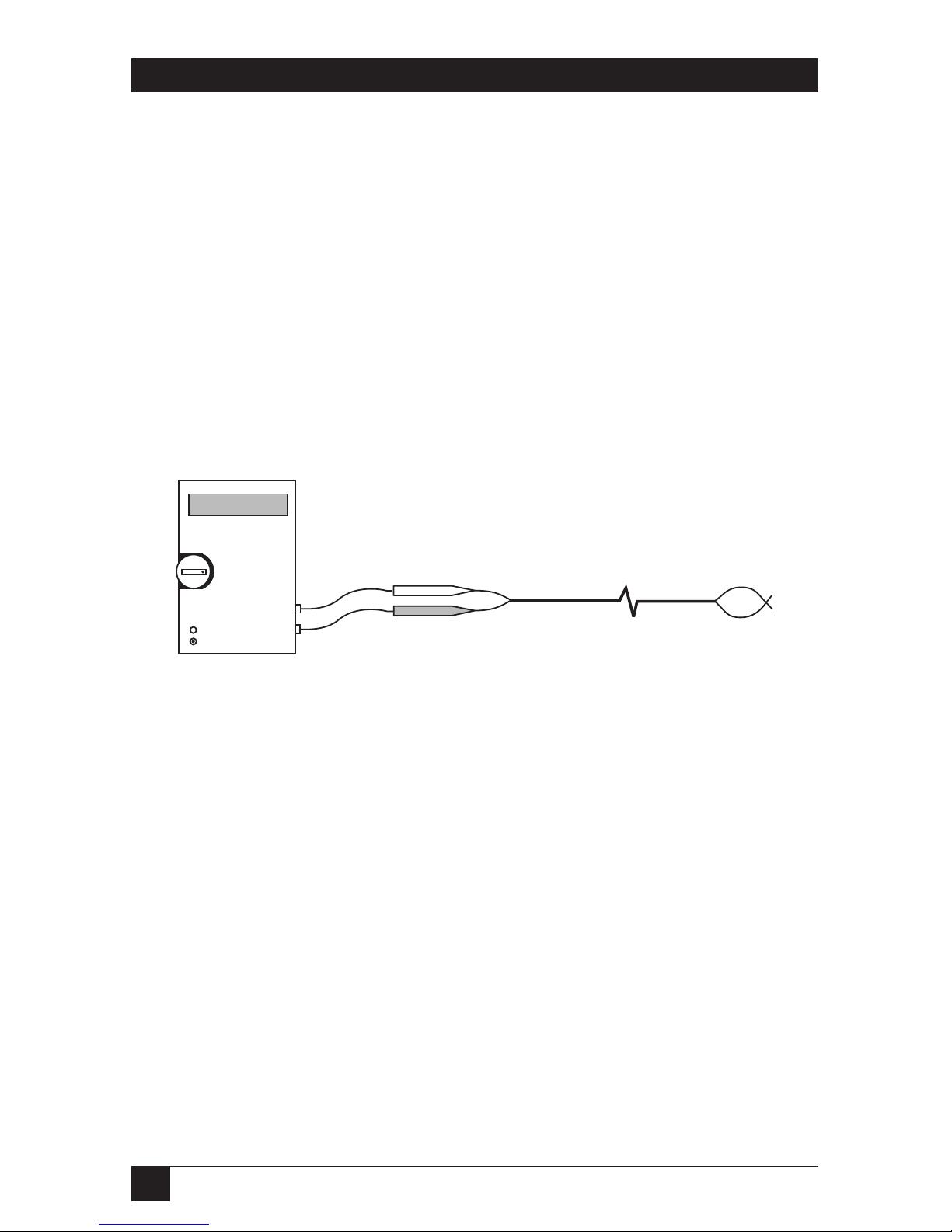
performing a DC resistance test with a digital ohmmeter, as shown in
Figure 3-1. 1000 feet (305 m) of 24-AWG cable should give a reading of
approximately 26 ohms (52 ohms if you are measuring at one end with the
opposite cable ends shorted).
Figure 3-1. Measuring cable impedance.
The Video CCTV-A/V Hub must be kept away from sources of radiofrequency or electromagnetic radiation; at least:
a) 5" (12.7 cm) from power lines carrying 2 kVA or less.
b) 12" (30.5 cm) from fluorescent lighting and power lines carrying between
2 and 5 kVA.
c) 36" (91.4 cm) from power lines greater than 5 kVA.
d) 40" (101.6 cm) from transformers and motors.
You’ll get the best performance by using a single continuous run of cable. Do
not use flat-satin cable (that is, cable whose wires aren’t twisted), even for
patching short runs. Flat-satin cable acts as an antenna and will pick up
nearby radio-frequency interference.
METER
Hub end
UTP
Balun end
Page 12
11
CHAPTER 3: Installation
4. Identify the pinout of all involved video baluns and the Video CCTV-A/V
Hub to see whether you’ll need to use any cross-pinned cable. For example, if
you’re using all Video Stereo Audio Baluns (IC441A-R2), all of the UTP cable
can be straight-through-pinned. Table 3-1 shows the pinouts of several of the
baluns that can be used with the hub and straight-through-pinned cable.
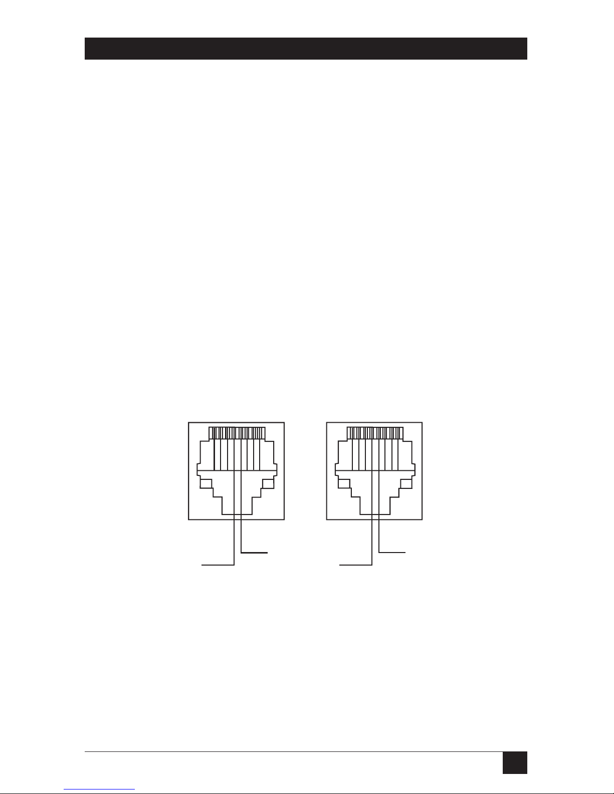
Figure 3-2 shows the difference between a balun RJ-45 pinning that needs
straight-through cable (straight polarity) and one that needs cross-pinned
cable (reverse polarity).
Table 3-1. Sample balun pinouts.
IC440A IC441A-R2 IC446A IC447A
Video 1 7 & 8 7 & 8 7 & 8 7 & 8 Y/luminance
Video 2 N/A N/A 4 & 5 4 & 5 C/chrominance
Audio 1 N/A 1 & 2 1 & 2 N/A
Audio 2 N/A 3 & 6 3 & 6 N/A
Figure 3-2. Connector signal polarity for the “video 2” signal.
1 2 3 4 5 6 7 8
1 2 3 4 5 6 7 8
R
T
R
T
Straight polarity
(ring on 4, tip on 5)
Reverse polarity
(tip on 4, ring on 5)
Page 13
12
VIDEO CCTV-A/V HUB
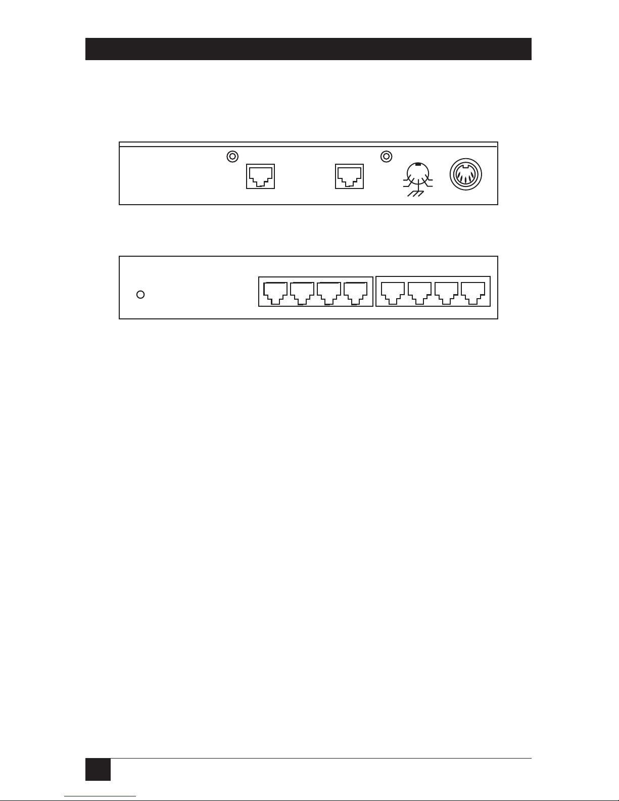
5. Run the hub’s power cord from the 5-pin DIN power inlet on its rear panel,
shown in Figure 3-3, to the nearest working AC power outlet. The Power LED
on its front panel, shown in Figure 3-4, should light up and stay on.
Figure 3-3. The hub’s rear panel.
Figure 3-4. The hub’s front panel.
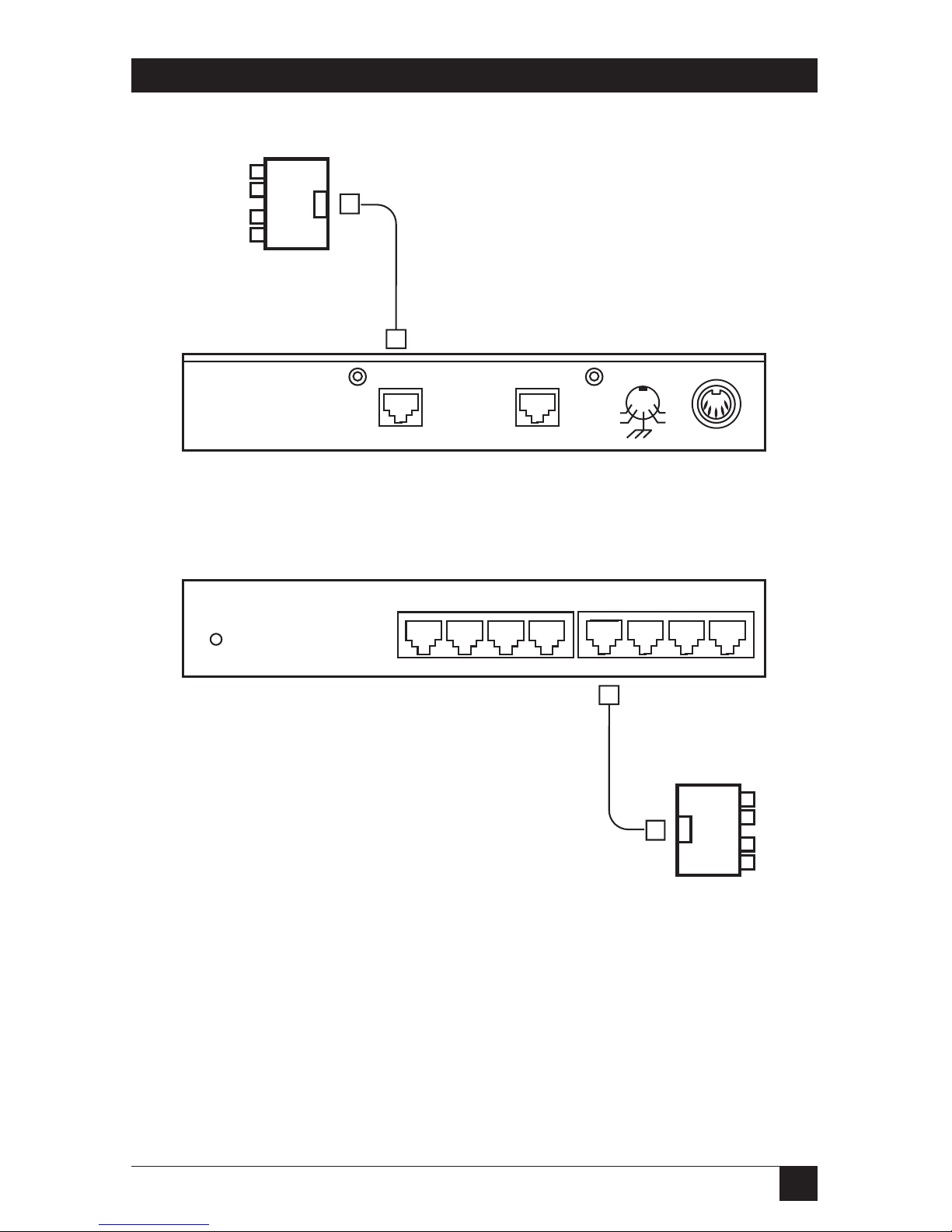
6. Connect the cable coming from the A/V source devices to the RJ-45 input
jack on the hub’s rear panel, as shown in Figure 3-5.
7. One at a time, connect the twisted-pair cables coming from the A/V
destination devices into the RJ-45 output jacks on the hub’s front-panel, as
shown in Figure 3-6.
8. Power on the source and destination equipment and send an audio/video
signal from the source. Verify the presence and quality of the audio and
video. If anything’s wrong, refer to Section 4.1.
Input
(RJ-45)
(RJ-45)
Normal outputs 1 through 8 (all RJ-45)
Looping output
Power
(5-pin DIN)
Power
LED
Page 14
13
CHAPTER 3: Installation
Figure 3-5. Balun-to-hub input connection (IC446A balun shown).
Figure 3-6. Hub-to-balun output connection (IC446A balun shown).
Straight-through
4-pair CAT5 cable
with RJ-45 plugs
Straight-through
4-pair CAT5 cable
with RJ-45 plugs
Dual Audio/Video
Balun (IC446A)
Audio 1
Video 1
Audio 2
Video 2
Audio 1
Video 1
Audio 2
Video 2
Dual Audio/Video
Balun (IC446A)
Page 15
14
VIDEO CCTV-A/V HUB
3.2 Typical Applications
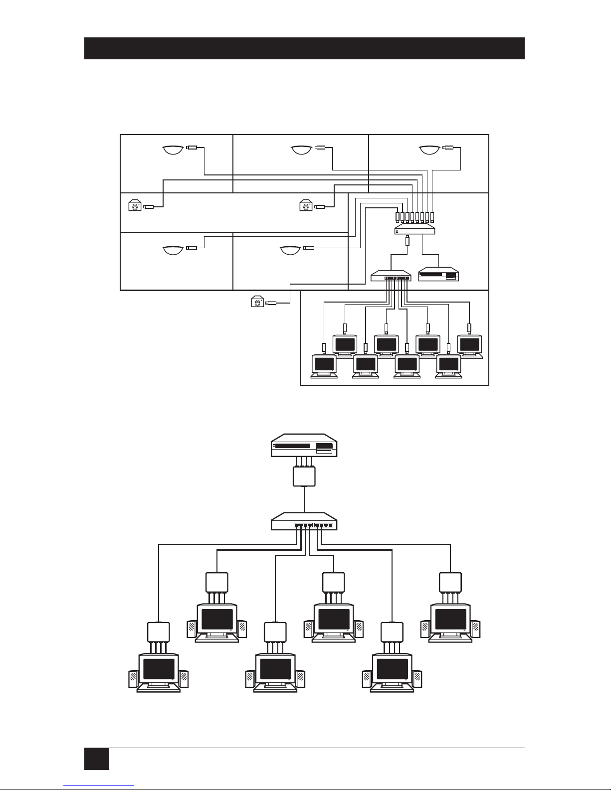
Figures 3-7 and 3-8 show a pair of typical applications.
Figure 3-7. A hub-based closed-circuit security video system.
Figure 3-8. A hub-based classroom-video-broadcast system.
Fixed cameras in
hallway and stairwell
Fixed camera
in parking lot
Baluns are all
CCTV Balun
(IC444A); hub-
to-balun cables
are all CAT5
UTP with at
least one pair
Baluns are all
Video Stereo
Audio Balun
(IC441A-R2);
hub-to-balun
cables are all
CAT5 UTP
with at least
three pairs
Hub
VCR or DVD
player
Monitors with
powered
speakers
Monitoring
station
Video
switch
(input from
cameras,
output to
hub and
VCR)
Hub
VCR
Omnidirectional
cameras in rooms
Page 16
15
CHAPTER 3: Installation
3.3 Installing a Hub in a Daisychain or Cascade
One Video CCTV-A/V Hub may be daisychained or cascaded with others in order
to distribute a baseband A/V source to more than eight destinations. For example,
an A/V presentation from a VCR or DVD player can be distributed to multiple
classrooms using preinstalled CAT5 twisted-pair cable, as shown in Figures 3-9 and
3-10. Due to the active electronics in the hub, you can daisychain or cascade as
many as eight layers of hubs together.
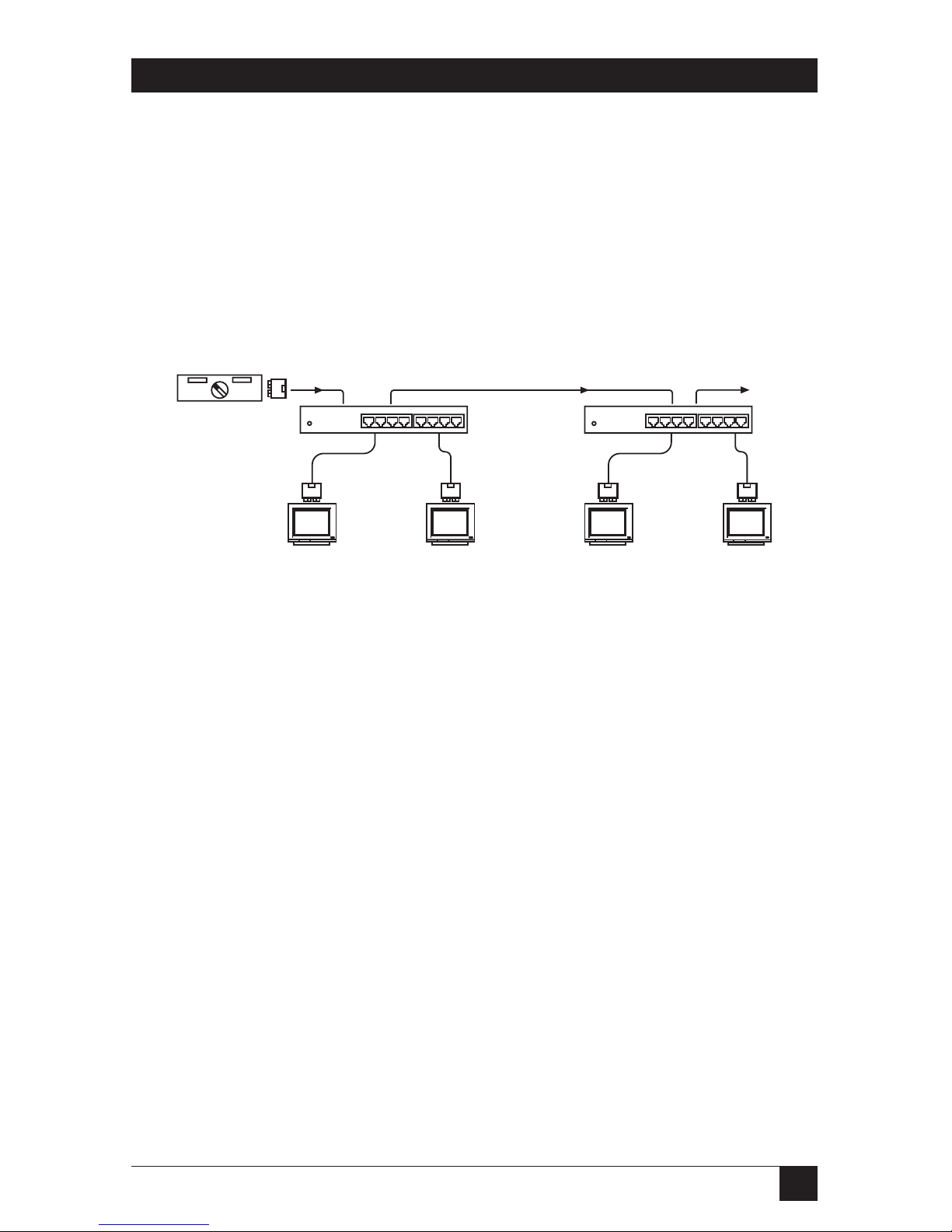
Figure 3-9. Daisychaining hubs.
To daisychain hubs as shown in Figure 3-9 without occupying any of your regular
output ports, you can use the Video CCTV-A/V Hub’s “looping output” RJ-45 jack,
the right-hand RJ-45 jack on its rear panel. To link one hub to a second hub, run a
4-pair CAT5 cable from the looping output of the first hub to the input port of the
second hub (the left-hand RJ-45 jack on its rear panel). The cable must be straightthrough-pinned and terminated with RJ-45 plugs on either end. Your daisychain
can be as many as eight hubs long.
NOTE
The regular “distribution port” outputs and the looping output don’t
amplify the signal. The maximum distance from the source device to the
most distant destination device may be up to 2500 feet (762 m)
depending on the type of A/V signal being transmitted. The hub can be
used with cross-connect blocks and patch panels, but each crossconnect results in an effective loss of distance of 5 to 10 feet (1.5 to
3 m). When splicing connections onto a cross-connect block, make sure
that the individual wires remain twisted right up to within half an inch
(1.3 cm) of the cross-connect.
VCR or DVD
player
Hub #1
TV
monitors
TV
monitors
Hub #2
• • • • • •
• • • • • •
To hub #3
To hub #3
In this example,
baluns are all
Video Stereo Audio
Balun (IC441A-R2);
cables are all CAT5
UTP with at least
three pairs
Page 17
16
VIDEO CCTV-A/V HUB
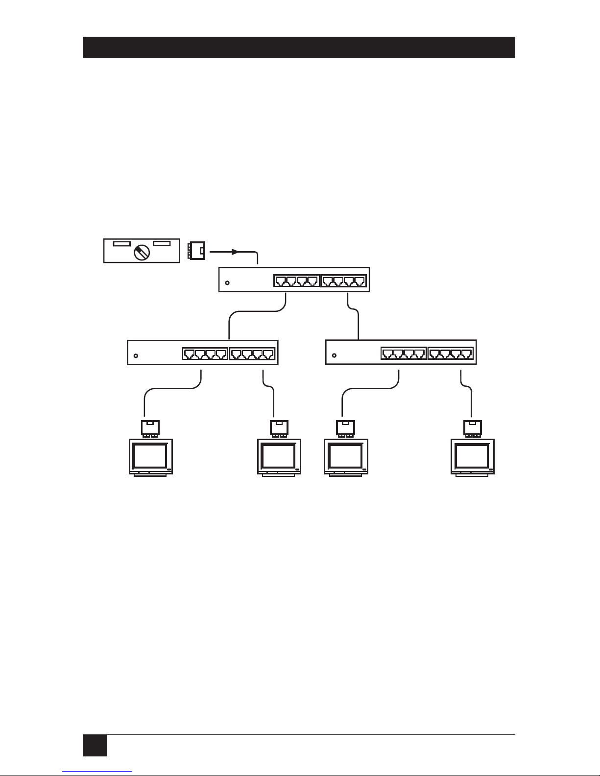
If you need to reach more destinations than eight hubs can accommodate, you
can cascade from each hub to multiple others as shown in Figure 3-10 instead of
daisychaining. The regular outputs and looping output can all be used for this
purpose—any of these ports may be connected to the input port of another hub.
In the example in Figure 3-10, ten hubs (one first-layer hub, one not-shown
second-layer hub attached to its looping output, and eight other second-layer hubs
connected to its regular outputs) are used to distribute an A/V program to up to
72 monitors in an auditorium, multi-classroom, or corporate training environment.
Figure 3-10. Cascading hubs.
In this example, baluns are
all Video Stereo Audio
Balun (IC441A-R2); cables
are all CAT5 UTP with at
least three pairs; an
additional hub not shown
here, attached to the first-
layer hub’s looping output,
reaches classroom #1
VCR or DVD
player
First-layer hub
Second-layer hub #2
Second-layer hub #9
Classroom #2
Monitor 9 Monitor 65 Monitor 72Monitor 16
Classroom #9
• • • • • •
• • • • • •
• • • • • •
TV
monitors
TV
monitors
Page 18

17
CHAPTER 4: Troubleshooting
4. Troubleshooting
4.1 Common Concerns
Here are some problems that can occur with the Video CCTV-A/V Hub and some
of their possible causes and solutions:
The Power LED doesn’t come on.
The hub’s probably not getting any power. Make sure that the hub’s power cord is
securely plugged into both the hub and a working AC outlet. If necessary,
temporarily plug another device into the outlet to make sure that the outlet works.
You get no video image or audio.
The UTP cable might be disconnected or broken, or there might be an open
wiring path or split or crossed twisted pairs. Try these remedies: Check all of your
UTP connections; verify wiring continuity with an ohmmeter; check the pinning
and pairing of your UTP cabling; and make sure the pinouts of all of the baluns
you’re using match the hub’s.
You get a distorted video image.
The signal polarity might be reversed; there might be a cable pinning, pairing, or
construction problem; or there might be a pinning mismatch between the hub and
baluns. Try these remedies: Verify that polarity is straight through on each A/V
channel; verify that the pinouts of all of the baluns you’re using match the hub’s;
check the pinning and pairing of your UTP cabling; and make sure that the pairs
in your UTP cabling are fully twisted up to the connection points.
The picture is clear but has lost color.
The end-to-end link is probably suffering excessive signal loss. Make sure that your
cable connections are secure; that your equipment and cables are well away from
neon and fluorescent lights, generators, electric motors, high-voltage lines, and
other sources of high-voltage or high-frequency electromagnetic signal; and that
you’re not trying to run your UTP cabling too far. (The maximum distance over
which the hub and baluns can transmit and receive video signals depends on your
cable and your video and audio equipment; refer to the Maximum Distance
specification in Chapter 1.)
Page 19

18
VIDEO CCTV-A/V HUB
4.2 Calling Black Box
If you determine that the Video CCTV-A/V Hub is malfunctioning, do not attempt to
alter or repair the unit. It contains no user-serviceable parts. Contact Black Box
Technical Support at 724-746-5500.
Before you do, make a record of the history of the problem. We will be able to
provide more efficient and accurate assistance if you have a complete description,
including:
• the nature and duration of the problem;
• when the problem occurs;
• the components involved in the problem, including the models of baluns;
type, make, and length of cabling; and the source and destination A/V
equipment;
• any particular application that, when used, appears to create the problem or
make it worse; and
• the results of any testing you’ve already done.
4.3 Shipping and Packaging
If you need to transport or ship your Video CCTV-A/V Hub:
• Package it carefully. We recommend that you use the original container.
• If you ever ship the hub back to us for any reason, contact Black Box to get a
Return Authorization (RA) number.
Page 20

1000 Park Drive • Lawrence, PA 15055-1018 • 724-746-5500 • Fax 724-746-0746
© Copyright 2002. Black Box Corporation. All rights reserved.
Doc. No. 94-000338-A
 Loading...