

Black Box IC404A-R2, IC406A-R2 User Manual
USER MANUAL
IC404A-R2, IC406A-R2
4-PORT
USB 2.0 FIBER
EXTENDER
24/7 TECHNICAL SUPPORT AT 1.877.877.2269 OR VISIT BLACKBOX.COM
+
Link
Host
Power
+
Activity
+
+
Link
Host
Power
Activity

NEED HELP?
LEAV E TH E TEC H TO US
LIVE 24/7
TABLE OF CONTENTS
TECHNICAL
SUPPORT
1. 8 7 7. 877. 2269
PRODUCT OPERATION AND STORAGE........................................................................................................................................... 3
1. SPECIFICATIONS ........................................................................................................................................................................... 4
2. OVERVIE W ................................................... ................................................................................................................................... 5
2.1 Introduction ............................................................................................................................................................................................... 5
2.2 Features .................................................................................................................................................................................................... 5
2.3 What’s Included ........................................................................................................................................................................................5
2.4 Additional Items You Will Need ............................................................................................................................................................... 5
2.5 Hardware Description ..............................................................................................................................................................................6
2.5.1 Local Extender MM or SM (IC404A-R2 or IC406A-R2) .............................................................................................................................. 6
2.5.2 Remote Extender MM or SM (IC404A- R2 or IC406A-R2) ........................................................................................................................ 8
3. INSTALLATION ............................................................................................................................................................................ 10
3.1 Preparing for Installation .......................................................................................................................................................................10
3.2 Installing the Local Extender .................................................................................................................................................................10
3.3 Installing the Remote Extender ............................................................................................................................................................. 10
3.4 Connecting the Local Extender to the Remote Extender ...................................................................................................................11
3.5 Connecting a USB Device ...................................................................................................................................................................... 11
3.6 Checking the Installation ....................................................................................................................................................................... 11
3.7 Compatibility ...........................................................................................................................................................................................12
3.8 USB Extender Mounting (Optional) ......................................................................................................................................................12
4. TROUBLESHOOTING ................................................................................................................................................................... 15
4.1 Troubleshooting Tips .............................................................................................................................................................................15
4.2 Contacting Technical Support ..............................................................................................................................................................17
APPENDIX A. REGULATORY INFORMATION ................................................................................................................................ 18
A.1 FCC Radio Frequency Interference Statement Warning ............................................................................................................ ......... 18
A.2 CE Statement ......................................................................................................................................................................................... 18
A.3 IC Statement ..........................................................................................................................................................................................18
A.4 WEEE Statement .................................................................................................................................................................................... 18
A.5 NOM Statement ..................................................................................................................................................................................... 19
APPENDIX B. DISCLAIMER/TRADEMARKS ................................................................................................................................. 20
B.1 Disclaimer ...............................................................................................................................................................................................20
B.2 Trademarks Used in this Manual ............................................................................................................ ..............................................20
2
1. 8 77. 8 7 7. 2 2 69 BLACKBOX.COM

NEED HELP?
LEAV E TH E TEC H TO US
LIVE 24/7
PRODUCT OPERATION AND STORAGE
TECHNICAL
SUPPORT
1. 8 7 7. 877. 2269
Please read and follow all instructions provided with this product, and operate for intended use only.
Do not attempt to open the product casing as this may cause damage and will void warranty. Use only the power supply provided with this
product. When not in use, the product should be stored in a dry location between -4 to +158° F (-20 to +70° C).
1. 8 77. 8 7 7. 2 2 69 BLACKBOX.COM
3

CHAPTER 1: SPECIFICATIONS
TABLE 1-1. SPECIFICATIONS
SPECIFICATION DESCRIPTION
General
Distance
USB Device Support Speeds
Maximum Throughput
Traffic Types All USB 2.0 and 1.1 traffic types
Dev ice Ty p es All USB 2.0 and 1.1 device types
Maximum Number of Devices Up to 30 devices
Local Extender
USB Connector (1) USB 2.0 Type B receptacle
Link Connector (1) SFP duplex LC
Dimensions 1"H x 3.9"W x 3"D (2.6 x 10 x 7.6 cm)
Enclosure Material Black anodized aluminum
Remote Extender
USB Connector (4) USB 2.0 Type A receptacles
Link Connector (1) SFP duplex LC
Dimensions 1”H x 3.9”W x 3”D (2.6 x 10 x 7.6 cm)
Enclosure Material Black anodized aluminum
Available Current Up to 1 Amp per port; 2.5 Amps total shared
Power Supply
Environmental
Operating Temperature Range 32 to 122° F (0 to 50° C)
Storage Temperature Range -4 to +158° F (-20 to +70° C)
Operating Humidity 20 to 80% relative humidity, noncondensing
Storage Humidity 10 to 90% relative humidity, noncondensing
Compliance
FCC Class B
CE Class A
Environmental RoHS2
IC404A-R2: Up to 1600 feet (500 m) over multimode ber (OM2+);
IC406A-R2: Up to 6.2 miles (10 km) over single-mode ber
USB 2.0: Up to 480 Mbps;
USB 1.1: Up to 12 Mbps
Input: 100 -240 VAC
Output: 24 VDC, 1 A
NEED HELP?
LEAV E TH E TEC H TO US
LIVE 24/7
TECHNICAL
SUPPORT
1. 8 7 7. 877. 2269
4
1. 8 77. 8 7 7. 2 2 69 BLACKBOX.COM

NEED HELP?
LEAV E TH E TEC H TO US
LIVE 24/7
CHAPTER 2: OVERVIEW
TECHNICAL
SUPPORT
1. 8 7 7. 877. 2269
2.1 INTRODUCTION
The instructions in this guide assume a general knowledge of computer installation procedures, familiarity with cabling
requirements, and some understanding of USB devices.
The 4-Port USB 2.0 MM Fiber Extender (IC404A-R2) extends high-speed USB 2.0 connections up to 1600 feet (500 m) using
multimode fiber optic cable. The 4-Port USB 2.0 SM Fiber Extender (IC406A-R2) extends up to 6.2 miles (10 km) over single-mode
fiber optic cable. Both SM and MM models extend USB peripherals including keyboards, mice, interactive whiteboards, flash drives,
hard drives, audio devices, web cameras, and any other USB device across a dedicated fiber optic connection.
CAUTION: The local and remote extenders may be hot to the touch during operation.
2.2 FEATURES
Supports USB throughputs of up to 480 Mbps
Operates with USB 2.0 and 1.1 devices and hubs
Supplies up to 1 Amp per USB port and 2.5 Amps total shared for all four ports used concurrently
Integrated hub provides ports for four USB devices, use hubs to add more
Supports mass storage acceleration for USB 2.0 device bulk transfer speeds
Provides electrical isolation
Offers transparent USB extension
True plug-and-play; no software drivers needed
Works with all major operating systems, including Windows
True plug and play; no software drivers required
Works with all major operating systems: Windows
®
, Mac OS™ and Linux®
®
, Mac OS®, and Linux®.
2.3 WHAT’S INCLUDED
Your package should include the following items. If anything is missing or damaged, contact Black Box Technical Support
at 877-877-2269 or info@blackbox.com.
Local Extender
Remote Extender
International AC Power Adapter
Country Specific Power Cord
USB 2.0 Cable
Quick Start Guide
1. 8 77. 8 7 7. 2 2 69 BLACKBOX.COM
5
CHAPTER 2: OVERVIEW
2.4 ADDITIONAL ITEMS YOU WILL NEED
To complete the installation, you will also require the following items that are not included with the product:
USB 1.1 or 2.0 compatible computer (host computer) with a USB compliant operating system
USB 1.1 or 2.0 compatible device(s)
Fiber optic cabling
2.5 HARDWARE DESCRIPTION
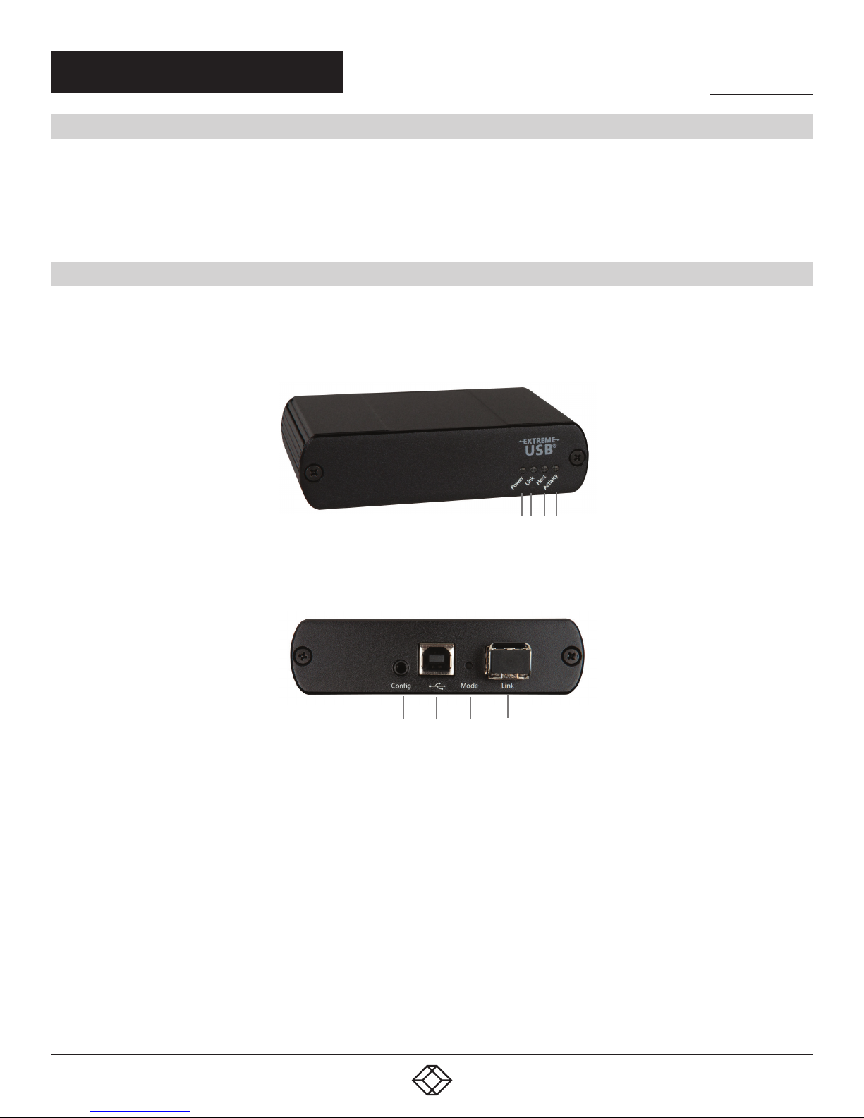
2.5.1 LOCAL EXTENDER MM or SM (IC404A-R2 or IC406A-R2)
The local extender connects to the computer using a standard USB cable (included).
Figures 2-1 and 2-2 show the front and back of the Local Extender. Table 2-1 describes its components.
NEED HELP?
LEAV E TH E TEC H TO US
LIVE 24/7
TECHNICAL
SUPPORT
1. 8 7 7. 877. 2269
1 2 3 4
FIGURE 2-1. LOCAL EXTENDER, FRONT VIEW
5 6 7 8
FIGURE 2-2. LOCAL EXTENDER, BACK VIEW
6
1. 8 77. 8 7 7. 2 2 69 BLACKBOX.COM

NEED HELP?
LEAV E TH E TEC H TO US
LIVE 24/7
CHAPTER 2: OVERVIEW
TECHNICAL
SUPPORT
1. 8 7 7. 877. 2269
TABLE 2-1. LOCAL EXTENDER COMPONENTS
NUMBER IN FIGURE 2-1 OR 2-2 COMPONENT DESCRIPTION
1 Power LED (Blue)
2 Link LED (Green)
3 Host LED (Green)
4 Activity LED (Amber)
5 Config Reserved for future use.
6 USB host port Used to connect the local extender to the host computer. Accepts USB Type B connector.
7 Mode Reserved for future use.
8 Link Port (duplex LC) Extension link duplex LC fiber optic transceiver port.
LED turns on when power is supplied.
LED is off when no power is supplied by the host computer.
Indicates a valid link is established between the local and remote extender.
LED turns on when link between the local and remote extenders is established.
LED is off when there is no link between the local and remote extenders.
LED is slow blinking when the unit is attempting to establish a link.
Indicates that the extender system is properly enumerated on the host computer.
LED blinks when the extender system is in a suspended state.
Indicates data transmission is occurring between the local and remote extenders.
LED blinks intermittently with or without a USB device connected.
When the local and remote extenders are in suspend mode, the LED is off.
1. 8 77. 8 7 7. 2 2 69 BLACKBOX.COM
7
NEED HELP?
LEAV E TH E TEC H TO US
LIVE 24/7
CHAPTER 2: OVERVIEW
TECHNICAL
SUPPORT
1. 8 7 7. 877. 2269
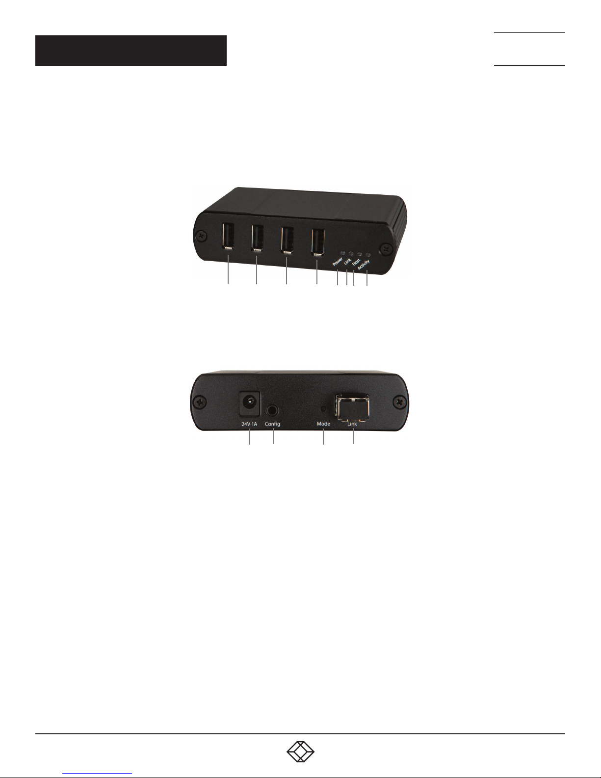
2.5.2 REMOTE EXTENDER MM or SM (IC404A-R2 or IC406A-R2)
The remote extender provides a USB Type A port for connecting standard USB devices. The remote extender allows you to connect four
USB devices directly. Additional devices may be connected by attaching USB hubs to the remote extender. The remote extender is powered
either directly by the included power supply.
Figures 2-3 and 2-4 show the front and back of the Remote Extender. Table 2-2 describes its components.
1 1 1 1 2 3 4 5
FIGURE 2-3. REMOTE EXTENDER, FRONT VIEW
6 7 8 9
FIGURE 2-4. REMOTE EXTENDER, BACK VIEW
8
1. 8 77. 8 7 7. 2 2 69 BLACKBOX.COM
 Loading...