

Page 1
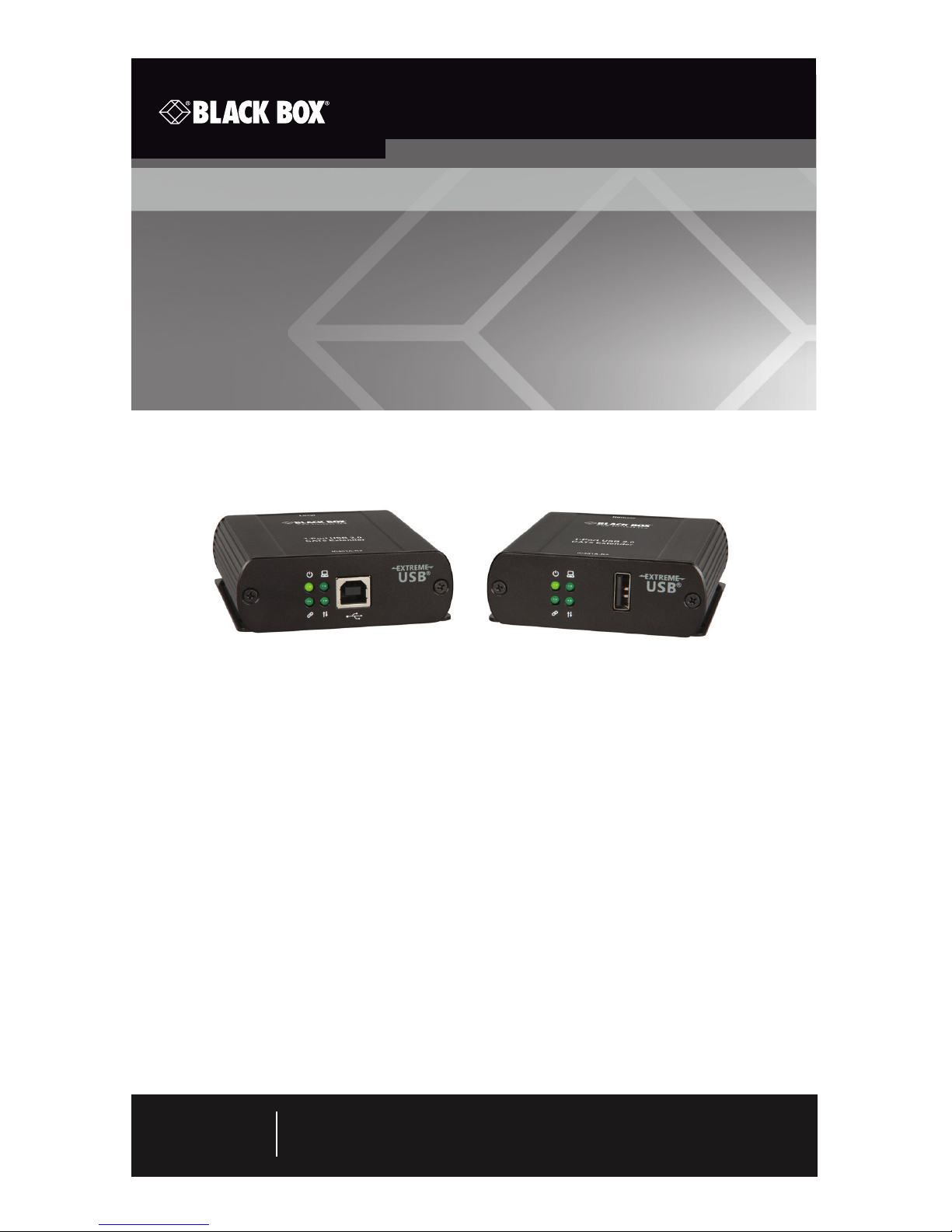
-R2
Break the USB distance barrier! Now you can
place USB devices up to 330 feet (100 meters)
from the computer.
Extends beyond the standard 1.5-foot (5-m) cable limit for USB peripheral
devices.
1-Port CAT5e/6/7 USB 2.0 Extender User Manual
Order toll-free in the U.S. or for FREE 24/ 7 technical suppport: Call 877-877-BBOX
(outside U.S. call 724-746-5500)
www.blackbox.com • nfo@ blackbox.com
Contact
Information
IC401A-R2
Page 2

Page 2
877-877-2269 | blackbox.com
IC401A-R2 User Manual
FCC and IC RFI Statements
FEDERAL COMMUNICATIONS COMMISSION AND
INDUSTRY CANADA RADIO FREQUENCY INTERFERENCE STATEMENTS
This equipment generates, uses, and can radiate radio-frequency energy,
Class B Digital Device. This equipment has been tested and found to comply with
the limits for a Class B computing device pursuant to Part 15 of the FCC Rules.
These limits are designed to provide reasonable protection against harmful interference in a residential installation. However, there is no guarantee that
interference will not occur in a particular installation. This equipment generates,
uses, and can radiate radio frequency energy, and, if not installed and used in
accordance with the instructions, may cause harmful interference to radio
communications. If this equipment does cause harmful interference to radio or
telephone reception, which can be determined by turning the equipment off and
on, the user is encouraged to try to correct the interference by one of the
following measures:
• Reorient or relocate the receiving antenna.
• Increase the separation between the equipment and receiver.
• Connect the equipment into an outlet on a circuit different from that to which
the receiver is connected.
• Consult an experienced radio/TV technician for help.
CAUTION: Changes or modifications not expressly approved by the party
responsible for compliance could void the user’s authority to operate
the equipment.
To meet FCC requirements, shielded cables and power cords are required to
connect this device to a personal computer or other Class B certified device.
This digital apparatus does not exceed the Class B limits for radio noise emission
from digital apparatus set out in the Radio Interference Regulation of Industry
Canada.
Le présent appareil numérique n’émet pas de bruits radioélectriques dépassant les
limites applicables aux appareils numériques de classe B prescrites dans le
Règlement sur le brouillage radioélectrique publié par Industrie Canada.
Page 3

Page 3
877-877-2269 | blackbox.com
IC401A-R2 User Manual
NOM Statement
Normas Oficiales Mexicanas (NOM)
Electrical Safety Statement
INSTRUCCIONES DE SEGURIDAD
1. Todas las instrucciones de seguridad y operación deberán ser leídas antes de
que el aparato eléctrico sea operado.
2. Las instrucciones de seguridad y operación deberán ser guardadas para
referencia futura.
3. Todas las advertencias en el aparato eléctrico y en sus instrucciones de
operación deben ser respetadas.
4. Todas las instrucciones de operación y uso deben ser seguidas.
5. El aparato eléctrico no deberá ser usado cerca del agua—por ejemplo,
cerca de la tina de baño, lavabo, sótano mojado o cerca de una alberca,
etc.
6. El aparato eléctrico debe ser usado únicamente con carritos o pedestales
que sean recomendados por el fabricante.
7. El aparato eléctrico debe ser montado a la pared o al techo sólo como sea
recomendado por el fabricante.
8. Servicio—El usuario no debe intentar dar servicio al equipo eléctrico más allá
lo descrito en las instrucciones de operación. Todo otro servicio deberá ser
referido a personal de servicio calificado.
9. El aparato eléctrico debe ser situado de tal manera que su posición no
interfiera su uso. La colocación del aparato eléctrico sobre una cama, sofá,
alfombra o superficie similar puede bloquea la ventilación, no se debe
colocar en libreros o gabinetes que impidan el flujo de aire por los orificios
de ventilación.
10. El equipo eléctrico deber ser situado fuera del alcance de fuentes de calor
como radiadores, registros de calor, estufas u otros aparatos (incluyendo
amplificadores) que producen calor.
11. El aparato eléctrico deberá ser connectado a una fuente de poder sólo del
tipo descrito en el instructivo de operación, o como se indique en el
aparato.
Page 4

Page 4
877-877-2269 | blackbox.com
IC401A-R2 User Manual
NOM Statement
12. Precaución debe ser tomada de tal manera que la tierra fisica y la
polarización del equipo no sea eliminada.
13. Los cables de la fuente de poder deben ser guiados de tal manera que no
sean pisados ni pellizcados por objetos colocados sobre o contra ellos,
poniendo particular atención a los contactos y receptáculos donde salen
del aparato.
14. El equipo eléctrico debe ser limpiado únicamente de acuerdo a las
recomendaciones del fabricante.
15. En caso de existir, una antena externa deberá ser localizada lejos de las
lineas de energia.
16. El cable de corriente deberá ser desconectado del cuando el equipo no sea
usado por un largo periodo de tiempo.
17. Cuidado debe ser tomado de tal manera que objectos liquidos no sean
derramados sobre la cubierta u orificios de ventilación.
18. Servicio por personal calificado deberá ser provisto cuando:
A: El cable de poder o el contacto ha sido dañado; u
B: Objectos han caído o líquido ha sido derramado dentro del aparato; o
C: El aparato ha sido expuesto a la lluvia; o
D: El aparato parece no operar normalmente o muestra un cambio en su
desempeño; o
E: El aparato ha sido tirado o su cubierta ha sido dañada.
Page 5

Page 5
877-877-2269 | blackbox.com
IC401A-R2 User Manual
Trademarks Used in this Manual
Trademarks Used in this Manual
Black Box and the Double Diamond logo are registered trademarks of
BB Technologies, Inc.
Mac is a registered trademark of Apple Computer, Inc.
Linux is a registered trademark of Linus Torvalds.
Windows is a registered trademark of Microsoft Corporation.
Any other trademarks mentioned in this manual are acknowledged to be
the property of the trademark owners.
Page 6

Page 6
877-877-2269 | blackbox.com
IC401A-R2 User Manual
Table of Contents
Table of Contents
1. Specifications.............................................................................................7
2. Overview ...................................................................................................8
2.1 Introduction ........................................................................................ 8
2.2 Features ..............................................................................................8
2.3 What’s Included .................................................................................9
2.4 Other Requirements ...........................................................................9
2.5 Hardware Description .......................................................................10
2.5.1 Local Extender (LEX) Unit ........................................................10
2.5.2 Remote Extender (REX) Unit ...................................................12
2.6 Typical Installation.............................................................................14
3. Installation ............................................................................................... 15
3.1 Installing the Local Extender (LEX) Unit ............................................15
3.2 Connecting the Local Extender (LEX) Unit to the
Remote Extender (REX) Unit .............................................................15
3.3 Installing the Remote Extender (REX) Unit ........................................16
3.4 Checking the Installation ..................................................................16
3.5 Connecting a USB Device ................................................................. 17
4. USB Extender Mounting Options ............................................................18
Option 1: USB Extender Mounting Kit ....................................................18
Option 2: USB Extender Direct Surface Mounting ...................................19
5. Troubleshooting ......................................................................................21
5.1 Troubleshooting Tips .........................................................................21
5.2 Contacting Black Box........................................................................23
5.3 Shipping and Packaging ...................................................................23
Appendix. Technical Glossary .........................................................................24
Page 7

Page 7
877-877-2269 | blackbox.com
IC401A-R2 User Manual
Chapter 1: Specifications
1. Specifications
Compliance — FCC Class B, CE Class B, RoHS2
Current Available to USB Device at Remote Unit —
Up to 1 A
Enclosure Material — Black anodized Aluminum
Maximum Number of USB Devices — Up to 30
Range — Direct Connect: 330 ft. (100 m) over solid-core
CAT5ee/6/7 cable
USB Device Support — High-speed devices (480 Mbps)
(USB 2.0),
Full-speed devices (12 Mbps) (USB 2.0 and 1.1),
Low-speed devices (1.5 Mbps) (USB 2.0 and 1.1)
Connectors — Local Extender Unit: (1) USB Type B, (1) RJ-45;
Remote Extender Unit: (1) USB Type A, (1) RJ-45
Temperature Tolerance — Operating: +32 to +122° F
(0 to +50° C);
Storage: -4 to +158° F (-20 to +70 °C)
Humidity Tolerance — Operating: 20 to 80% relative
humidity, noncondensing;
Storage: 10 to 90% relative humidity, noncondensing
Power — Remote Unit:
Input: 100/240 VAC, 50–60 Hz, 600 mA maximum;
Output: 5 VDC, 3 A;
Available Current: Up to 1 A per USB port
Size — Local Extender Unit: 3.4"H x 3"W x 1"D
(8.6 x 7.6 x 2.6 cm);
Remote Extender Unit: 3.4"H x 3"W x 1"D
(8.6 x 7.6 x 2.6 cm)
Page 8

Page 8
877-877-2269 | blackbox.com
IC401A-R2 User Manual
Chapter 2: Overview
2. Overview
2.1 Introduction
The 1-Port CAT5e/6/7 USB 2.0 Extender increases the distance from your
computer to a wide variety of USB devices—from printers, scanners, hard drives,
and audio devices to touchscreens, Web cams, and game controllers. USB devices
can be located up to 100 meters (330 feet) from the computer. The extender is
composed of two individual units: the Local Extender (LEX) unit and the Remote
Extender (REX) unit.
The instructions in this guide assume a general knowledge of computer
installation procedures, familiarity with cabling requirements, and some
understanding of USB devices.
NOTE: Notes provide additional information that could be useful.
CAUTION: Cautions provide important information about an operational
requirement.
2.2 Features
• Extends USB 2.0 high-speed and USB 1.1 (low-speed, full-speed) devices up to
330 feet (100 m) over CAT5e/6/7 cable.
• Operates with USB 3.0 host controllers and devices (up to 480 Mbps).
• Supports all USB device types.
• True plug-and-play, ready to operate right out of the box. No new driver
installation required.
• Supports all major operating systems, including Windows®, Mac® OS, and
Linux®.
• Provides (1) remote USB 2.0 port. Number of devices can be increased using
additional USB hubs.
• AC power adapter at remote extender unit supplies standard 1 A to USB port.
• Power adapter at local extender unit is not required for normal operation.
Page 9

Page 9
877-877-2269 | blackbox.com
IC401A-R2 User Manual
Chapter 2: Overview
2.3 What’s Included
Your 1-Port CAT5e USB 2.0 Extender includes the following items. If anything
is missing or damaged, contact Black Box Technical Support at 877-877-2269
or [email protected].
• (1) Local Extender unit (LEX)
• (1) Remote Extender unit (REX)
• (1) AC power adapter for Remote Extender unit
• (1) 6-foot (1.8-m) USB 2.0 cable
• A quick start guide
The full user manual/installation guide you are reading can be downloaded from
the Black Box Web site. Go to www.blackbox.com, enter the part number
(IC401A-R2) in the search box, click on the product in the “Product Results” page,
then click on the “Support” tab on the product page, and select the document
you wish to download.
2.4 Other Requirements
To complete the installation, you will also need the following items that are not
included with the product:
• USB 1.1 or 2.0 compatible computer (host computer) with a USB compliant
operating system.
• USB 1.1 or 2.0 compatible device.
• CAT5e/6/7 Unshielded Twisted Pair (UTP) cable with two RJ-45 connectors
(if using surface cabling),
OR,
CAT5e/6/7 cabling with two information outlets and two CAT5e/6/7 patch
cords with RJ-45 connectors (if using premise cabling).
NOTE: All references to CAT5e cable in this document represent the minimum
requirement of solid core CAT5e unshielded twisted-pair cable. You can
substitute Category 5e/6/7 or STP cable.
Page 10
Page 10
877-877-2269 | blackbox.com
IC401A-R2 User Manual
Chapter 2: Overview
2.5 Hardware Description
2.5.1 The Local Extender (LEX) Unit
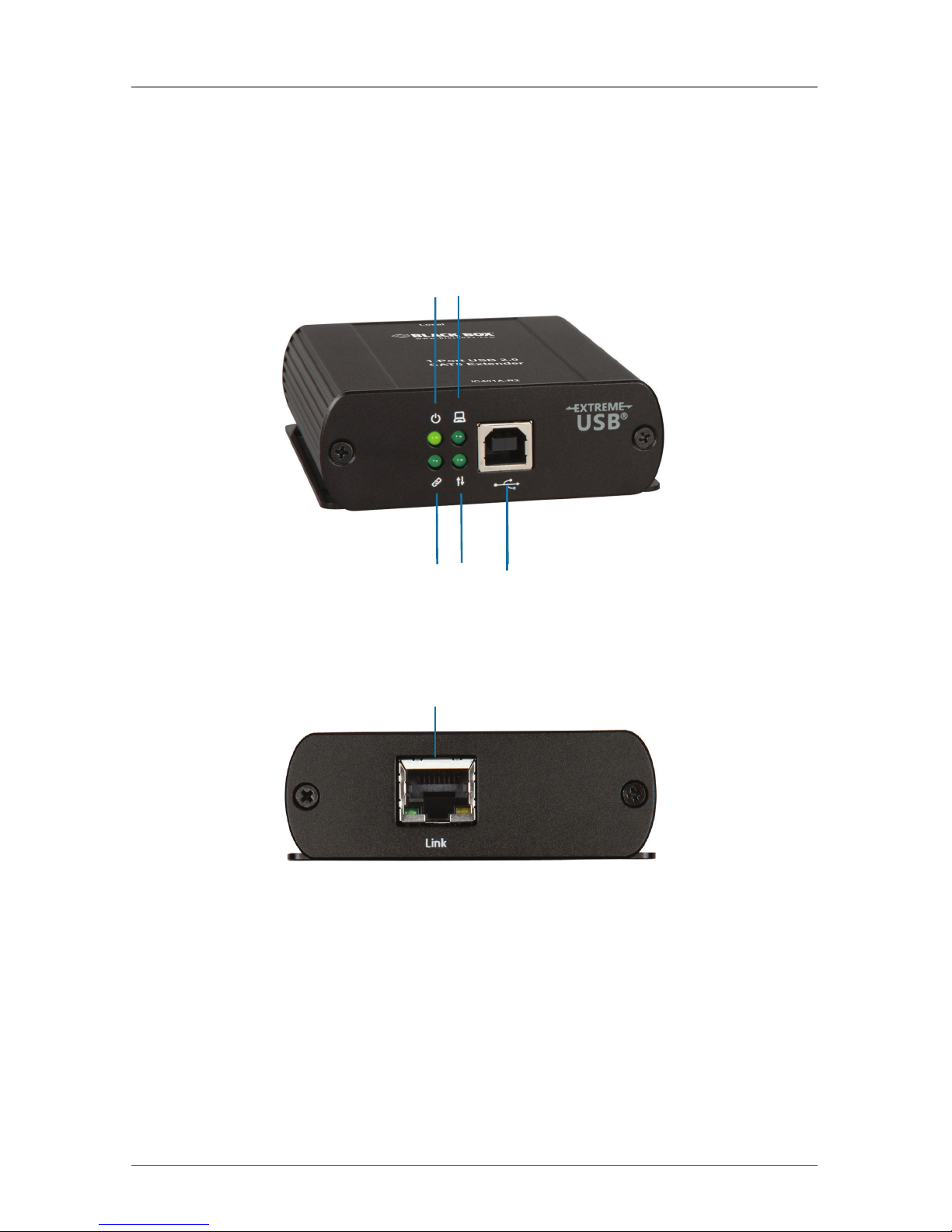
The LEX unit connects to the computer using a standard USB cable. Power for this
unit is provided by the USB on the host computer. Figures 2-1 and 2-2 show the
front and back panels of the LEX. Table 2-1 describes their components.
1 2
3 4 5
Figure 2-1. Front view: local unit.
6
Figure 2-2. Back view: local unit.
Page 11
Page 11
877-877-2269 | blackbox.com
IC401A-R2 User Manual
Chapter 2: Overview
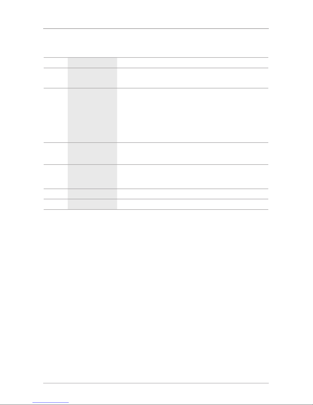
Table 2-1. Local (LEX) Unit Components.
Number Component Description
1 Power LED (Blue)
LED turns on when power is supplied. Off when no power is supplied by
the host computer.
2 Link LED (Green)
Indicates a valid link is established between the LEX and the REX units
over CAT5e cabling.
LED turns on when link between local and remote extender is established.
LED is off when there is no link between local and remote extenders.
LED is slow blinking when the unit is attempting to establish a link.
LED is fast blinking to indicate the unit is in Pairing Mode.
3 Host LED (Green)
Indicates that the extender system is properly enumerated on the host PC.
LED blinks when the extender system is in a suspended state.
4 Activity LED (Amber)
Indicates activity when data transmission is active between the LEX
and REX units. LED blinks intermittently with or without a USB device
connected. When the LEX and REX are in suspend mode, the LED is off.
5 USB Type B connector Connects the LEX unit to the host computer.
6 Link Port (RJ- 45) Accepts an RJ-45 connector for CAT5e/6/7 cabling to the REX unit.
Page 12
Page 12
877-877-2269 | blackbox.com
IC401A-R2 User Manual
Chapter 2: Overview
2.5.2 The Remote Extender (REX) Unit
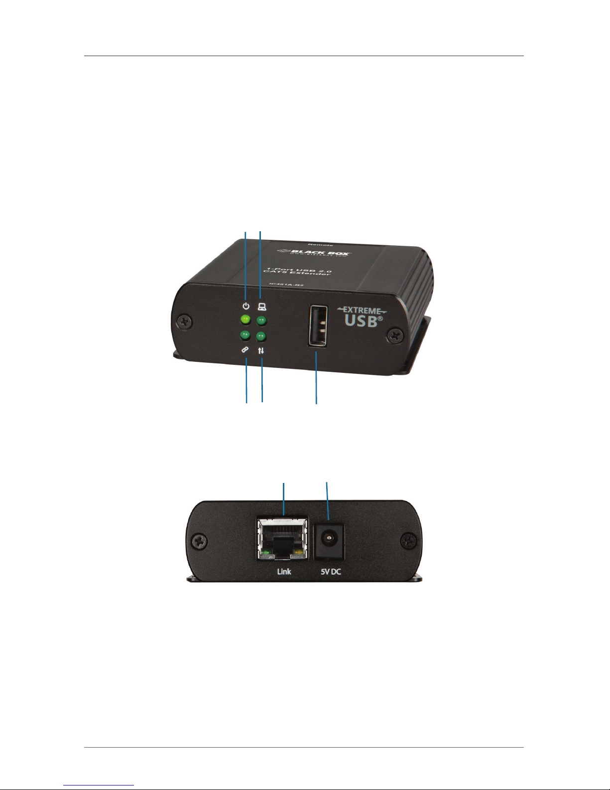
The REX unit provides USB Type A ports for standard USB devices. The REX unit
allows you to connect one (1) USB device directly. Additional devices may be
connected by attaching up to four USB hubs to the REX unit. The REX unit is
powered by an external AC adapter and can supply up to 1 A to each USB port.
Figures 2-3 and 2-4 show the front and back panels of the REX. Table 2-2
describes their components.
1 2
3 4 5
Figure 2-3. Front view: remote unit.
6 7
Figure 2-4. Back view: remote unit.
Page 13
Page 13
877-877-2269 | blackbox.com
IC401A-R2 User Manual
Chapter 2: Overview
Table 2-2. Remote (REX) Unit Components.
Number Component Description
1 Power LED (Green) LED turns ON when power is supplied. OFF when no power is supplied.
2 Link LED (Green)
Indicates a valid link is established between the local and remote
extender.
LED turns on when link between local and remote extender is
established.
LED is off when there is no link between local and remote
extenders.
LED is slow blinking when the unit is attempting to establish a
link.
LED is fast blinking to indicate the unit is in Pairing Mode.
3 Host LED (Green)
Indicates that the extender system is properly enumerated on the host
PC.
LED blinks when the extender system is in a suspended state.
4 Activity LED (Green)
Indicates activity when data transmission is active between the LEX
and REX units.
LED blinks intermittently with or without a USB device
connected.
When the LEX and REX are in suspend mode, the LED is off.
5 Device Port (USB Type A) Accepts USB devices.
6 Link Port (RJ- 45)
Accepts R J-45 connector for CAT5e/6 /7 cabling to connect the local
extender to the remote extender unit.
7 Power Port
Connects to the AC power supply. Required at REX for proper
operation.
Page 14
Page 14
877-877-2269 | blackbox.com
IC401A-R2 User Manual
Chapter 2: Overview
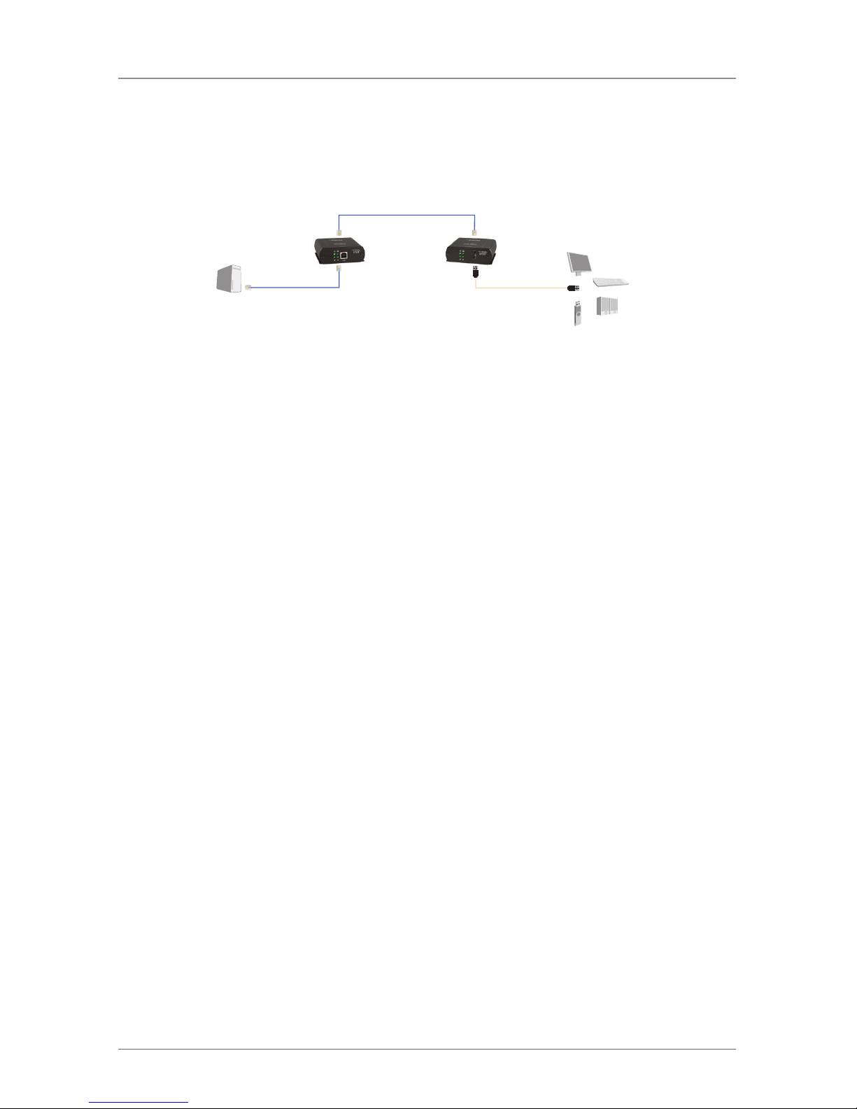
2.6 Typical Installation
Host
computer
Local
Extender
Unit (LEX)
Remote
Extender
Unit (REX)
USB 2.0 and 1.1
devices
USB over 328 feet
(100 m) CAT5e or
CAT6/7 cable
Figure 2-5. USB extension up to 328 feet (100 m) using CAT5e (or better) cable.
Page 15

Page 15
877-877-2269 | blackbox.com
IC401A-R2 User Manual
Chapter 3: Installation
3. Installation
Before you can install the extender, you need to prepare your site:
1. Determine where the computer is to be located and set up the computer.
2. Locate the USB device(s) within 330 feet (100 m) cable-length of the computer.
If not, adjust the location of the devices and/or computer accordingly.
3. If you are using surface cabling, install the CAT 5e/6/7 cabling as desired and
terminate it with the appropriate RJ-45 ends.
4. If you are using premise cabling (in-building network infrastructure), ensure
your cabling does not exceed 330 feet (100 m) and that it meets CAT5e/6/7
specification.
NOTE: Cable installation is important, particularly if high throughput applications
are used. When installing, ensure the cable is installed away from
or isolated from potential sources of interference such as electrical wiring,
fluorescent lighting, etc.
NOTE When terminating cables, ensure the matching RJ45 connector is used
for the cable type. For example, if you are using CAT6 cable, then be sure
to use CAT6 compatible RJ-45 connectors. If the cable and connector types
do not match, the benefits of higher grade cabling may not be realized.
3.1 Installing the Local Extender (LEX) Unit
1. Place the local extender near the computer.
2. Connect the supplied USB cable between the local extender host port and a
USB port on the host computer.
3.2 Connecting the Local Extender to the Remote Extender
With Surface Cabling:
1. Connect the CAT 5e/6/7 cable into the Link port of the local extender.
2. Connect the CAT 5e/6/7 cable into the Link port of the remote extender.
With Premise Cabling:
1. Connect a CAT 5e/6/7 patch cable (not provided) into the information outlet
near the host computer.
2. Connect the patch cable into the Link port of the local extender.
3. Connect a CAT 5e/6/7 patch cable (not provided) into the information outlet
near the USB devices.
Page 16

Page 16
877-877-2269 | blackbox.com
IC401A-R2 User Manual
Chapter 3: Installation
4. Connect the patch cable into the Link port of the remote extender.
3.3 Installing the Remote Extender (REX) Unit
1. Place the remote extender near the USB device.
2. Assemble the power adapter and country specific power cord together and
connect them into a suitable AC outlet.
3. Connect the power adapter to the remote extender.
3.4 Checking the Installation
1. On the LEX and REX units, check that the Power, Activity, Host, and Link LEDs
are on. If the Host or Link LEDs are permanently off, then the cabling between
the LEX and REX unit is not installed properly or is defective.
2. For Windows users, open Device Manager to confirm that the extender has
installed correctly. Expand the entry for Universal Serial Bus controllers by clicking the + sign. If the extender has been installed correctly, you should find it
listed as a “Generic USB Hub.”
NOTES:
To open Device Manager in Windows XP: Right click “My Computer” then select:
Properties >> Hardware tab >> Device Manager.
To open Device Manager in Windows 7: Open the Start Menu, right click on
“Computer” then select: Manage >> Device Manager.
To open Device Manager in Windows 8, 8.1, or 10: Right click the Start Menu and
then select: Device Manager.
3. For OS X users, open the System Profiler to confirm that the extender
has installed correctly. In the left hand column under Hardware, select “USB”
and inspect the right hand panel. If the extender has been installed correctly,
you should find it listed as a “Hub” under the USB High-Speed Bus/USB Bus.
NOTE: To open System Profiler in OS X: Open the Finder, select Applications, then
open the Utilities folder and double click on the System Profiler icon.
4. If the extender is not detected correctly or fails to detect, consult Section 5,
Troubleshooting.
Page 17

Page 17
877-877-2269 | blackbox.com
IC401A-R2 User Manual
Chapter 3: Installation
3.5 Connecting a USB Device
1. Install any software required to operate the USB device(s). Refer to the
documentation for the USB device(s), as required.
2. Connect the USB device to the device port on the REX unit.
3. Check that the device is detected and installed properly in the operating
system.
Page 18
Page 18
877-877-2269 | blackbox.com
IC401A-R2 User Manual
Chapter 4: USB Extender Mounting Options
4. USB Extender Mounting Options
The bottom of the IC401A-R2 enclosures feature four convenient pre-drilled holes
for optional direct surface mounting and four mounting slots for easy cable-ties.
Based on your requirements, choose from three available mounting options:
1. USB Extender Mounting Kit (part number IC401MK)
2. USB Extender Direct Surface Mounting
3. USB Extender Cable-Tie Mounting
Option 1: USB Extender Mounting Kit
USB Mounting Kit - Black (part number IC401MK)
NOTE: 1 kit required to mount per Local Extender or Remote Extender.
Each kit includes:
• (2) mounting brackets
• (4) (M2.5) locking washers
• (4) (M2.5 x 7.0mm) Phillips pan head screws
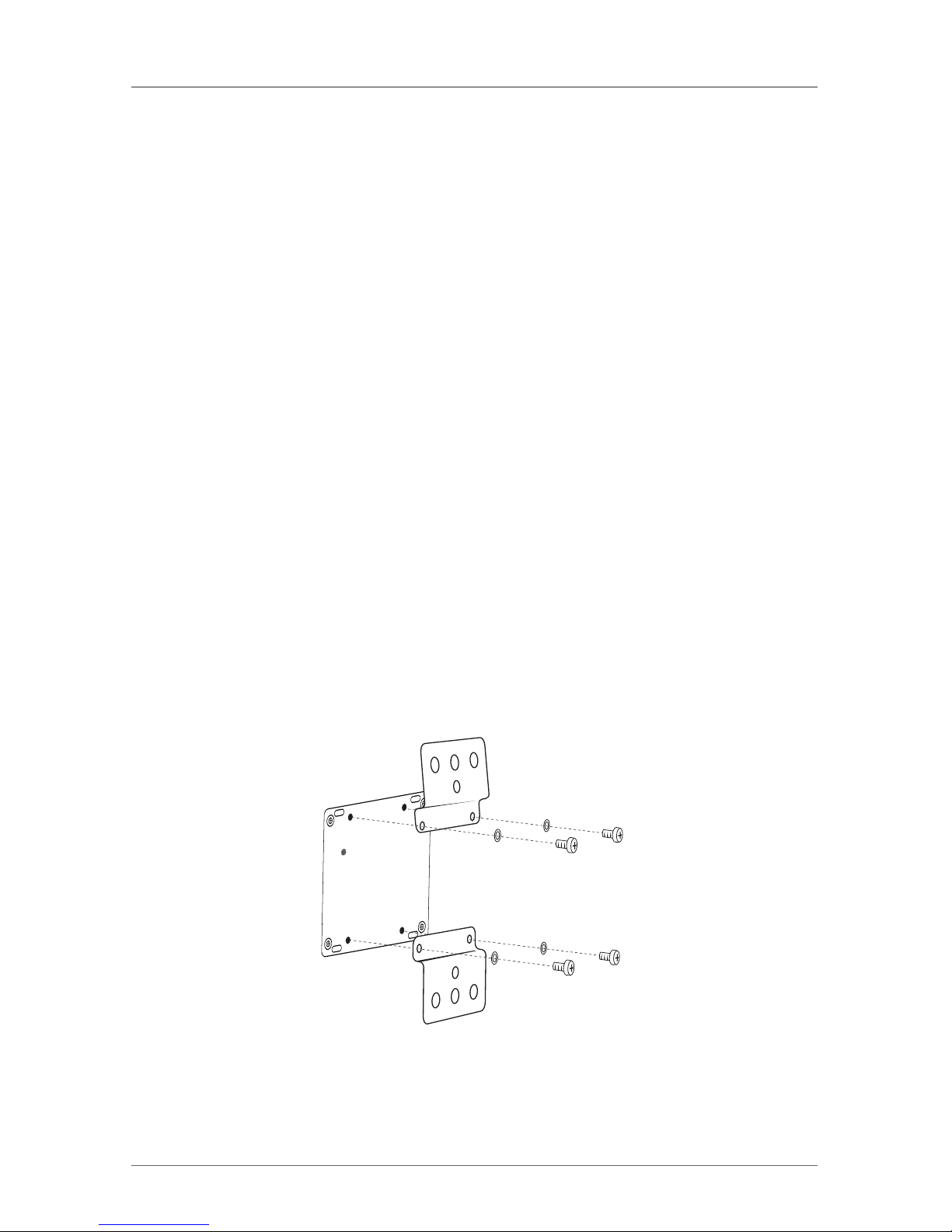
Installing the Mounting Brackets
Using a Phillips screwdriver, in the order as illustrated below, fasten and secure
the provided screws, locking washers and brackets into place.
Figure 4-1. Installing the mounting bracket.
Page 19
Page 19
877-877-2269 | blackbox.com
IC401A-R2 User Manual
Chapter 4: USB Extender Mounting Options
Option 2: USB Extender Direct Surface Mounting (using your own
hardware)
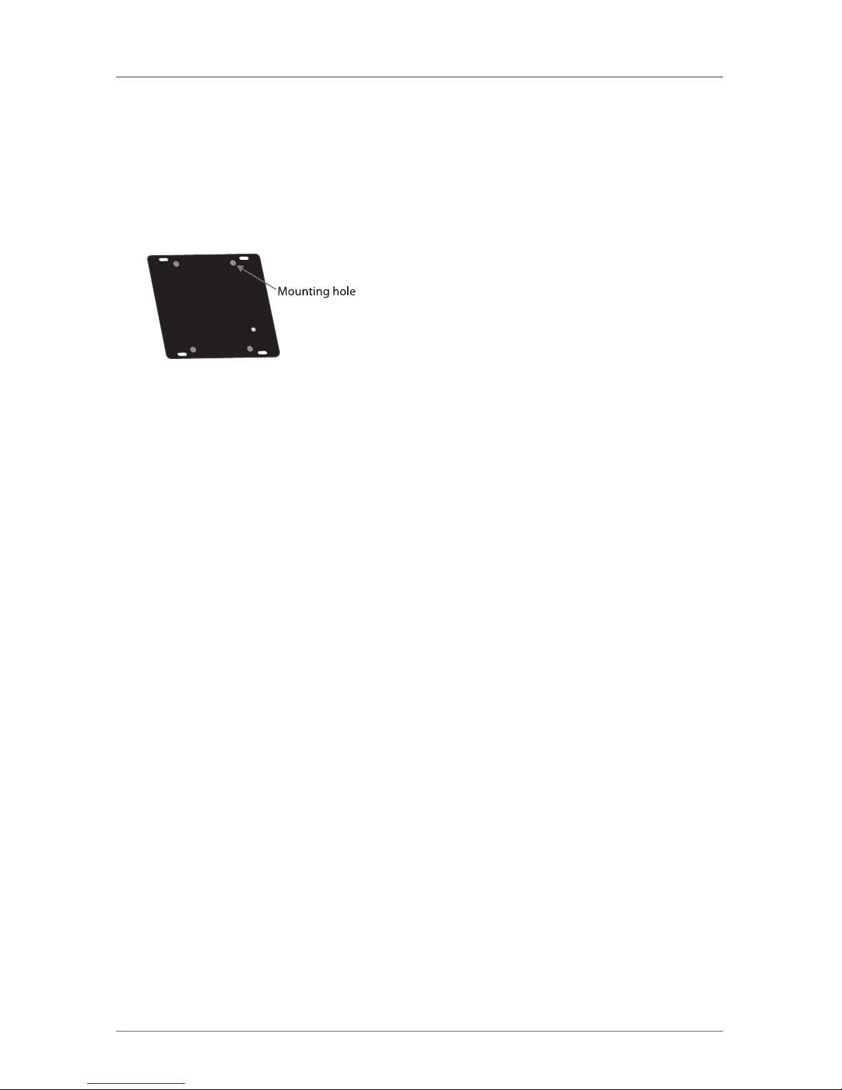
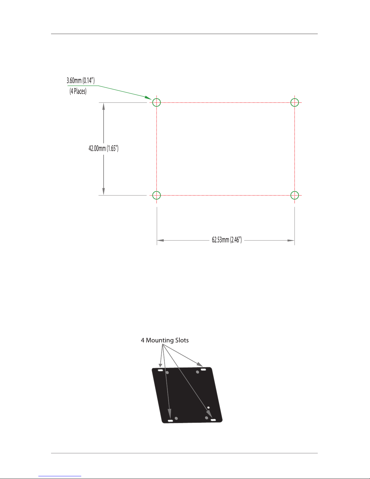
The bottom of the IC401A-R2 enclosures feature four pre-drilled holes for
optional direct surface mounting. Using the stencil below, along with your own
hardware you can directly mount your USB Extender on a surface.
Distance between the enclosure
mounting holes:
42.00 x 62.53mm
Figure 4-2. Direct surface mounting.
1. Mark the center point of each of the four holes on your mounting surface
either by directly measuring or using a printout of the stencil on the next page.
2. Hardware recommendation: M2.5 locking washers and M2.5 screws
(4 of each per extender) noting screw length will depend upon thickness
of mounting surface.
3. Drill through each of the four hole markings on the mounting surface
using a 3.70-mm (0.1457") drill bit.
4. Align the bottom enclosure holes to the newly drilled out holes on the
mounting surface.
5. Place a locking washer on each of the four screws and using a screwdriver,
fasten the extender into place.
NOTE: To ensure the stencil on the next page prints to scale be sure to set the
page scaling setting to “none”.
Page 20
Page 20
877-877-2269 | blackbox.com
IC401A-R2 User Manual
Chapter 4: USB Extender Mounting Options
Direct Surface Mounting Measurement Stencil
Figure 4-3. Mounting measurement stencil.
Option 3: Cable-Tie Mounting
The bottom of the IC401A-R2 enclosure also features four convenient slots
for cable mounting. Simply thread a cable tie, (also called tie-wrap or zip tie),
into the mounting slot and through the cable tie head, and secure it to a pole
or other surface by pulling it tight. Cable ties are not included with this system
due to varying lengths dependent upon the application.
Figure 4-4. Cable-tie mounting.
Page 21
Page 21
877-877-2269 | blackbox.com
IC401A-R2 User Manual
Chapter 5: Troubleshooting
5. Troubleshooting
Table 5-1 provides troubleshooting tips. The topics are arranged in the order in
which they should be executed in most situations. If you are unable to resolve the
problem after following these instructions, contact Black Box Technical Support at
877-877-2269 or [email protected].
5.1 Troubleshooting Tips
Table 5-1. Problems/Causes/Solutions.
Problem Cause Solution
All LEDs on LEX
unit are off.
The LEX unit is not
receiving enough power
from the USB port or the
(optional) LEX AC adapter.
1. Ensure that the USB connection between the LEX and
host computer is properly installed.
2. Move the USB connector to another USB port on the
host computer.
All LEDs on REX
unit are off.
The REX unit is not
receiving enough power
from the AC adapter.
1. Ensure that the AC power adapter is properly connected
to the REX unit.
2. Check that the AC adapter is connected to a live source
of electrical power. Check that the REX power LED is
illuminated.
Link LEDs on LEX
unit and REX unit
are off.
There is no connection
between the LEX unit and
the REX unit.
1. Ensure CAT5e/ 6/7 cable is connected between the LEX
unit and the REX unit. Use CAT5e or better cable, UTP
with a straight-through connector and no crossovers,
and 8-pin RJ-45 connectors at both ends.
2. Connect a short CAT5e/6/7 patch cord between the
LEX unit and the REX unit to determine if the original
CAT5e/6 /7 cable is defective.
Extender units
were working, but
the Host LED on
the LEX/REX units
are suddenly
blinking.
The REX unit is in suspend
mode. The operating
system may put the
extender in suspend mode
when the computer is put
into a Suspend/Standby
state or when no USB
devices are attached.
1. Recover/ Resume the operating system from Suspend/
Standby mode (see your operating system’s
documentation).
2. Attach a USB device to the extender.
Page 22
Page 22
877-877-2269 | blackbox.com
IC401A-R2 User Manual
Chapter 5: Troubleshooting
Table 5-1 (Continued). Problems/Causes/Solutions.
Problem Cause Solution
All LEDs on both
the LEX unit and
the REX unit are
on, but the USB
device does not
operate correctly or
is detected as an
“Unknown Device”
in the operating
system.
• The USB device is
malfunctioning.
• The computer does not
recognize the USB
device.
• The application software
for the device is not
operating.
• The extender is
malfunctioning.
1. Disconnect the extender from the computer.
2. Connect the USB device directly to the USB port on the
computer.
3. If the device does not operate properly, consult the user
documentation for the device.
4. Update your system BIOS, chipset, or USB Host
controller drivers from your system/motherboard
manufacturer’s Web site.
5. If the device operates properly when directly connected
to the computer, connect another device (of a different
type) to the extender to the computer.
6. If the second device does not operate, the extender may
be malfunctioning. Contact Black Box Technical Support
at 724-746-5500 or [email protected].
7. If the second device does not operate properly, the first
device may not be compatible with the extender.
USB device is
attached to the
REX USB port, but
the REX device LED
is off.
A USB device must have
the appropriate driver
installed on the computer
operating system.
1. Install the required USB device driver on the computer
operating system before attaching the USB device to the
REX unit. See your USB device manufacturer’s Web site
for details.
2. Consult your USB device documentation and power
your USB device with the additional (USB device
manufacturer supplied) power supply (if available).
Device LED is
orange and units
are no longer
functioning.
An overcurrent condition
has occurred because the
USB device draws more
power than can be
supplied per USB
specification (500 mA).
Power cycle the REX.
Host and Link LEDs
on the LEX/REX
units blink
intermittently.
Firmware mismatch
between the LEX and the
REX.
1. Use a different LEX/REX pair that has the same firmware
revision.
2. Upgrade the LEX/REX firmware. Contact Black Box
Technical Support at 724-746-5500 or
[email protected] for assistance.
Page 23

Page 23
877-877-2269 | blackbox.com
IC401A-R2 User Manual
Chapter 5: Troubleshooting
5.2 Contacting Black Box
If you determine that your 1-Port CAT5e/6/7 USB 2.0 Extender is malfunctioning,
do not attempt to alter or repair the unit. It contains no user-serviceable parts.
Contact Black Box Technical Support at 877-877-2269 or [email protected].
Before you do, make a record of the history of the problem. We will be able to
provide more efficient and accurate assistance if you have a complete description,
including:
• the nature and duration of the problem.
• when the problem occurs.
• the components involved in the problem.
• any particular application that, when used, appears to create the problem or
make it worse.
5.3 Shipping and Packaging
If you need to transport or ship your 1-Port CAT5e/6/7 USB 2.0 Extender:
• Package it carefully. We recommend that you use the original container.
• If you are returning the unit, make sure you include everything you received
with it. Before you ship for return or repair, contact Black Box to get a Return
Authorization (RA) number.
Page 24
Page 24
877-877-2269 | blackbox.com
IC401A-R2 User Manual
Appendix: Technical Glossary
Appendix. Technical Glossary
Category 5e/6/7 (CAT5e/6/7) Network Cabling — Category 5 cable is com-
monly also referred to as CAT5e. This cabling is available in either solid or stranded
twisted-pair copper wire variants and as UTP (Unshielded Twisted Pair) or STP
(Shielded Twisted Pair). UTP cables are not surrounded by any shielding, making
them more susceptible to electromagnetic interference (EMI). STP cables include
shielding over each individual pair of copper wires and provides better protection
against EMI. Category 5 has been superseded by CAT5ee cabling, which includes
improved data integrity to support high-speed communications.
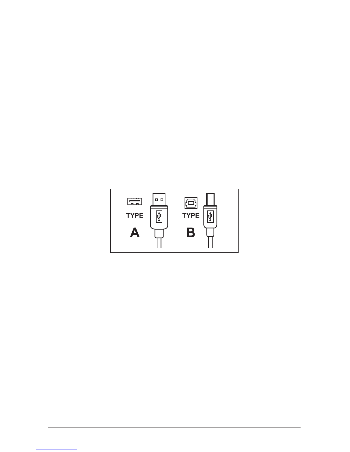
USB 2.0 Cables — USB 2.0 cables have two distinct connectors. The Type A
connector is used to connect the cable from a USB device to the Type A port
on a computer or hub. The Type B connector is used to attach the USB cable
to a USB device.
Figure A-1. USB connectors.
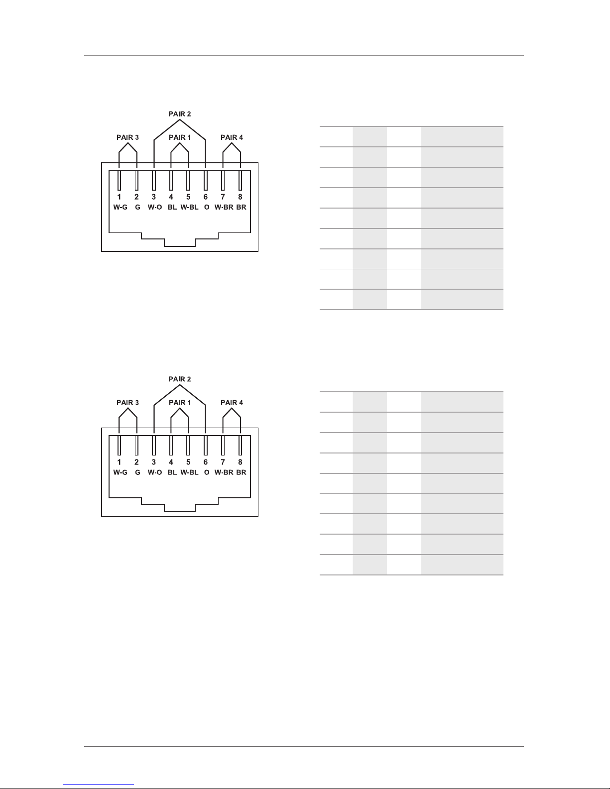
RJ-45 — The Registered Jack (RJ) physical interface is what connects the network
cabling (CAT5e) to the LEX unit and REX unit. You may use either the T568A
scheme (Table 6-1) or the T568B scheme (Table 6-2) for cable termination. The
1-Port CAT5e USB 2.0 Extender uses all four pairs of the cable. RJ-45 connectors
are sometimes also referred to as 8P8C connectors.
Page 25
Page 25
877-877-2269 | blackbox.com
IC401A-R2 User Manual
Appendix: Technical Glossary
RJ-45 Pin Positioning
Table A-1. T568A wiring.
Pin Pair Wire Cable Color
1 3 1 White/Green
2 3 2 Green
3 2 1 White/Orange
4 1 2 Blue
5 1 1 White /Blue
6 2 2 Orange
7 4 1 White /Brown
8 4 2 Brown
Table A-2. T568B wiring.
Pin Pair Wire Cable Color
1 2 1 White/Orange
2 2 2 Orange
3 3 1 White/Green
4 1 2 Blue
5 1 1 White /Blue
6 3 2 Green
7 4 1 White /Brown
8 4 2 Brown
Figure A-2. RJ-45 connector
using T568A wiring.
Figure A-3. RJ-45 connector
using T568B wiring.
Page 26

Page 26
877-877-2269 | blackbox.com
IC401A-R2 User Manual
NOTES
Page 27

Page 27
877-877-2269 | blackbox.com
IC401A-R2 User Manual
NOTES
Page 28
Black Box Tech Support: FREE! Live. 24/7.
Tech support the
way it should be.
Great tech support is just 60 seconds away at
877-877-2269 or blackbox.com.
877-877-2269 | blackbox.com
ic401a-r2_user_rev2
About Black Box
Black Box provides an extensive range of networking and infrastructure products.
You’ll find everything from cabinets and racks and power and surge protection
products to media converters and Ethernet switches all supported by free, live 24/7
Tech support available in 60 seconds or less.
© Copyright 2016. Black Box Corporation. All rights reserved.
 Loading...