

CUSTOMER
SUPPORT
INFORMATION
Order toll-free in the U.S. 24 hours, 7 A.M. Monday to midnight Friday: 877-877-BBOX
FREE technical support, 24 hours a day, 7 days a week: Call 724-746-5500 or fax 724-746-0746
Mail order: Black Box Corporation, 1000 Park Drive, Lawrence, PA 15055-1018
Web site: www.blackbox.com • E-mail: info@blackbox.com
DECEMBER 1999
IC235A
IC235AE
IC236A
IC236AE
RS-232↔MIL Std. Interface Converter
RS232↔MIL STD
POWER
TD RTS ST
RT CTS RD

3
TRADEMARKS
TRADEMARKS USED IN THIS MANUAL
UL is a registered trademark of Underwriters Laboratories Incorporated.
Product names mentioned in this manual may be trademarks or registered
trademarks of their respective companies and are hereby acknowledged.

4
Chapter Page
1. Specifications ................................................................................................5
2. Introduction..................................................................................................7
2.1 Description..............................................................................................7
2.2 Applications ............................................................................................7
3. Installation ..................................................................................................10
3.1 Installing the Converter ......................................................................11
3.2 Setting the RS-232 Interface ................................................................12
3.3 Setting the Interface Converter for MIL 188/114 Mode ..................13
3.4 Setting the Interface Converter for MIL 188C Mode ........................14
3.5 Tying Together Frame and Signal Ground ........................................14
4. Status Indicators..........................................................................................15
5. Troubleshooting ........................................................................................17
Appendix A: Signal Flow Diagrams..................................................................20
Appendix B: The Interfaces ............................................................................28
Contents

5
CHAPTER 1: Specifications
Connectors — RS-232 Interface: DB25 female;
MIL Std. Interface: DB25 female (pinned
in accordance with EIA standard RS-530,
which specifies a high-speed interface)
Data Rates— Speed transparent to a maximum of
64 Kbps
Interface — EIA Interface: RS-232C/V.24; used for async
or sync, depending on the model. Cannot
be configured by the user.
MIL Std. Interface: RS-530; the same for
both models. Cannot be configured by the
user.
Electrical Settings: MIL 188/114 or
MIL 188C. Configured by the user. Either
sync or async, depending on the model.
Operation — IC235A: Async; IC236A: Sync
Leads Supported — MIL 188C: Async: 1, 2, 3, 4, 5, 6, 7, 8, 20, 24;
Sync: 1, 2, 3, 4, 5, 6, 7, 8, 15, 17, 20, 24;
MIL 188/114: Async: 1, 2, 3, 4, 5, 6, 7, 8, 10,
11, 13, 14, 16, 19, 20, 22, 23, 24; Sync: 1, 2, 3,
4, 5, 6, 7, 8, 9, 10, 11, 12, 13, 14, 15, 16, 17,
19, 20, 22, 23, 24
Operating Temperature — 32 to 104°F (0 to 40°C)
Storage Temperature — 32 to 158°F (0 to 70°C)
Max. Altitude Tolerance — 15,000 feet (4572 m)
1. Specifications

6
Humidity Tolerance — Up to 90%, noncondensing
Power Supply — Regulated wall-mount transformer, UL
®
and CSA approved, +5 VDC, 12 VDC;
PS055: Primary: 104 to 125 VAC, 60 Hz,
10%; Secondary: +5 VDC @ 860 mA, 22 watts,
±12 VDC @ 300 mA; PS055E: Primary: 230
VAC, 50 Hz; Secondary: +5 VDC, 5 amps
Size — 2.5"H x 8"W x 6.25"D (6.4 x 20.3 x 16 cm)
Weight — With power supply, 3 lb. (1.4 kg)
A DB37 female connector may be specified as an option for the MIL 188
interface. Contact Black Box in order to request this option.
7
CHAPTER 2: Introduction
2.1 Description
The RS-232↔MIL Standard Interface Converter is a bi-directional converter
enabling you to connect RS-232 equipment to MIL 188/114 or 188C
equipment. The Converter is available in synchronous and asynchronous
models. The MIL Standard interface is pinned to the RS-530 mechanical
specs. The user is given the choice of configuring for balanced or unbalanced
operation. The converter is powered by a 115-VAC wall-mounted power
supply included with the unit. (A 230-VAC version is available upon request.)
2.2 Applications
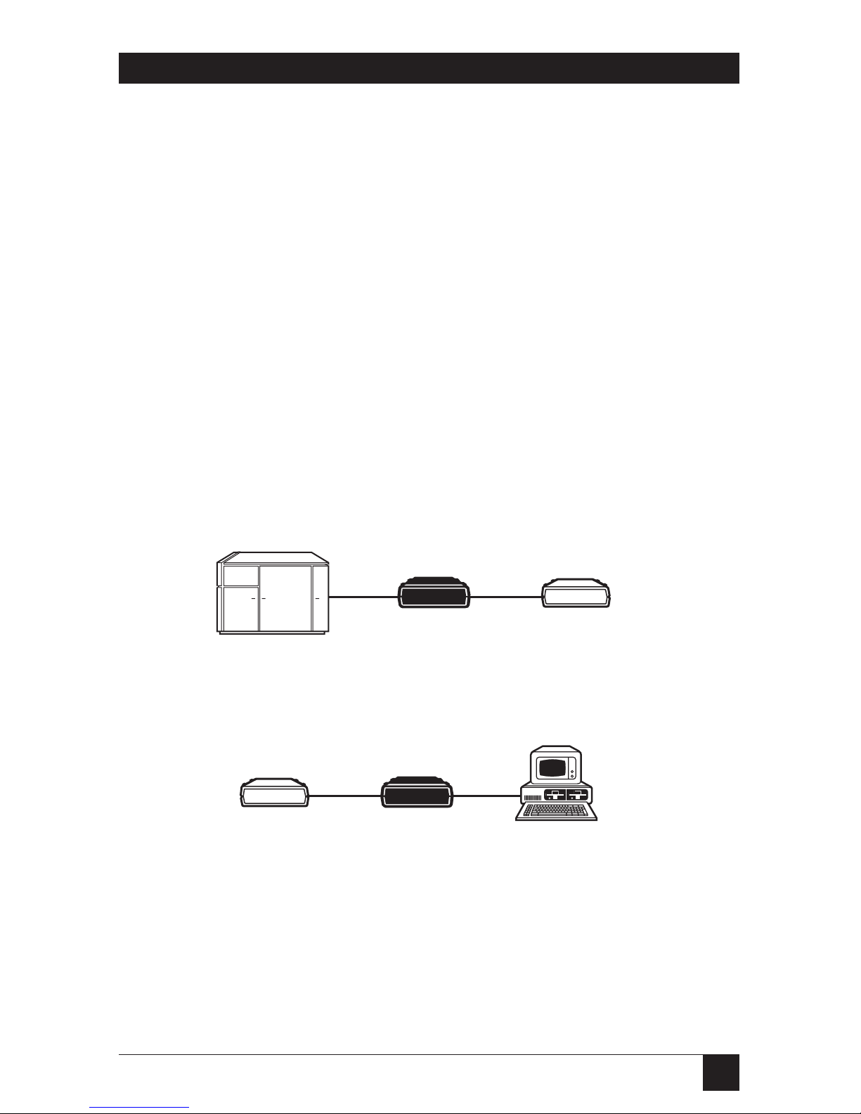
Figures 2-1 through 2-4 are included as examples of typical applications for
this interface converter. Use them to help you decide how to best use this
product.
Figure 2-1. Standard Applications.
RS232 Host
RS232 MIL 188
MIL Standard
(DCE)
(DTE)
Modem
(DCE)
(DTE)
Computer
Terminal
(DTE)
RS232
RS232 MIL 188
(DTE)
(DCE)
Modem
(DCE)
MIL Standard
2. Introduction
8
Figure 2-2. MIL 188 Async Applications Showing Pinning.
Note: Grounding is optional for the MIL 188/114 interface.
Figure 2-3. MIL 188/114 (Balanced)
Sync Application Showing Pinning.
(DTE)
RS-232
Synchronous
Terminal
RS-232 MIL 188/114
(DCE)
(DTE)
(DCE)
MIL 188/114
Modem
2
3
7
15
17
2
3
7
15
17
2
14
3
16
15
12
17
9
TDA
TDB
RDA
RDB
TCA
TCB
RCA
RCB
RS-232
RS-232 MIL 188/114
Any MIL 188/114
DCE Device
(DCE)
(DTE)
PC
(DTE)
2
14
3
16
RDA(-)
RDB(+)
TDA(-)
TDB(+)
Ground
Optional
for Balanced
2-2
3-3
7-7
4
5
6
8
20
Cable Pinout
RS-232
RS-232 MIL 188C
Any MIL 188C
DCE Device
(DCE)
(DTE)
PC
(DTE)
2
3
7
3 (RD)
2 (TD)
7 (SG)
2-2
3-3
7-7
4
5
6
8
20
Cable Pinout
9
CHAPTER 2: Introduction
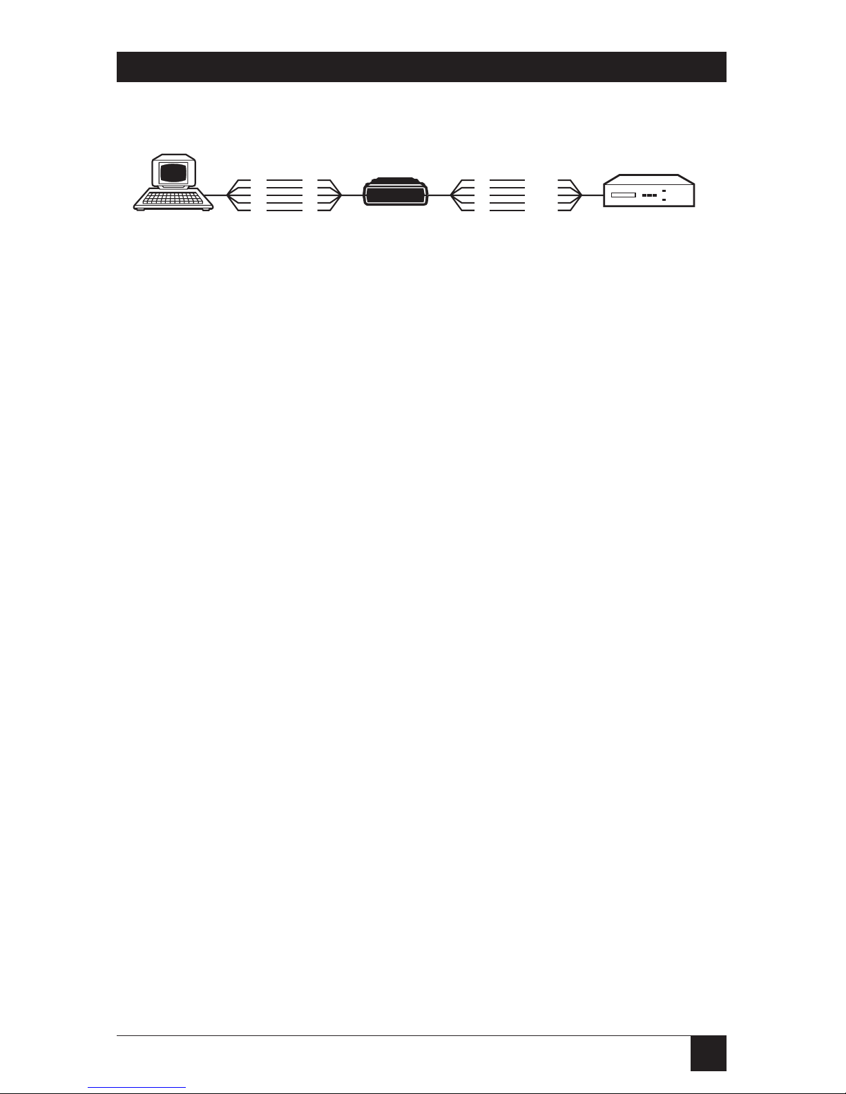
Figure 2-4. MIL 188C (Unbalanced) Sync Application Showing Pinning.
RS-232 MIL 188C
MIL 188C
Synchronous
Multiplexor
(DCE)
(DTE)
(DTE)
RS-232
Synchronous
Terminal
(DCE)
2
3
7
15
17
2
3
7
15
17
2
3
7
15
17
(TD) 2
(RD) 3
(SG) 7
(TC) 15
(RC) 17
10
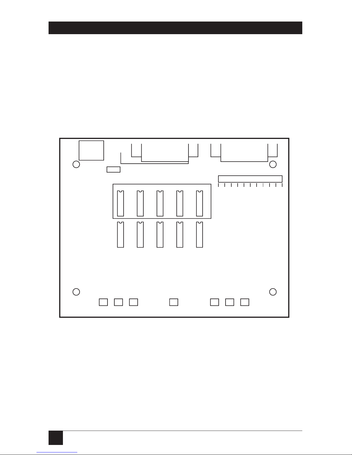
Figure 3-1 shows the location of components on the interface converter’s
circuit board. These components are described later in this chapter.
Figure 3-1. The Circuit Board.
J1A J2J1B
J3
GND
POWER MIL 188 RS232
TD RTS ST POWER RT CTS RD
JP1
W1
W2C W3C W4C W5C W6C
W2 W3 W4 W5 W6
DCE DTE
DCE DTE
DCE DTE
DCE DTE
DTE DCE
MIL 188/114 MIL 188C
DTE DCE
DTE DCE
DTE DCE
DTE DCE
DTE DCE
23456
8
151720
24
DCE
DTE
DCE
DTE
DCE
DTE
DCE
DTE
DCE
DTE
DCE
DTE
DCE
DTE
DCE
DTE
DCE
DTE
DCE
DTE
3. Installation

11
CHAPTER 3: Installation
3.1 Installing the Converter
Before attempting to install the interface, read these steps.
1. Make sure the package came with everything that should be included.
You should have received the RS-232↔MIL Standard Interface
Converter, this manual, and the wall-mounted power supply (either
115 or 230 VAC).
2. Open the interface converter case by removing the two screws
on the bottom of the unit with a Phillips-head screwdriver.
3. Set the jumpers and DIP shunts for your application according to the
directions found in Sections 3.2 through 3.5. See Figure 3-1 for the
location of these components.
4. Replace the top of the interface converter and secure it in place with the
two screws.
5. Attach the cable from the MIL Standard device to the MIL 188 connector
on the rear of the unit.
6. Attach the cable from the RS-232 device to the RS-232 connector on the
rear of the unit.
7. Plug the 5-pin adapter of the wall-mounted power supply into the power
connector on the rear of the unit. Then plug the three-prong connector
into a wall outlet. The unit is now ready for use.
Jumpers W6 and W6C need to be set only for synchronous operation of the
converter. They play no part in asynchronous communications.
Positions for jumpers and shunts are labeled “DCE” and “DTE” on the PC
board.
For proper operation of the interface converter, the status of the RS-232 and
MIL 188 sides of the converter must be opposite each other. For example, if
the RS-232 side is set to DCE, the MIL 188 side must be set to DTE.

12
3.2 Setting the RS-232 Interface
In order for the interface converter to operate properly, the RS-232 interface
must be set for either DCE or DTE operation. This can be done by setting the
push-on jumpers located on W1 (see Figure 3-2). Each pin of the RS-232
interface on the unit must be set either DCE or DTE, opposite to the
DCE/DTE status of the equipment you intend to connect to the RS-232 side
of the converter. Simply insert the push-on jumper (strap) for each pin onto
the header pins for either the DCE or DTE option. The factory-default
configuration of the RS-232 interface is set DCE.
Figure 3-2. Jumper W1.
2
3
4
5
6
8
15
17
20
24
W1
DCE
DTE
DCE
DTE
DCE
DTE
DCE
DTE
DCE
DTE
DCE
DTE
DCE
DTE
DCE
DTE
DCE
DTE
DCE
DTE

13
CHAPTER 3: Installation
3.3 Setting the Interface Converter for MIL 188/114 Mode
Jumpers W2 through W6 are used to configure the MIL 188 connector on
the interface converter for MIL 188/114 operation. Figure 3-3 shows an
isolated graphic of jumpers W2 through W6 set for DCE operation. Each
jumper must be configured for either DCE or DTE operation. This setting
should be opposite of the DCE/DTE status of the equipment you will attach
to the 188 side of the converter. Simply insert the jumper’s DIP shunts into
the proper positions. The factory-default configuration of the MIL 188C
interface is MIL 188C set to DTE.
NOTE
The DTE and DCE settings on jumper W6 are reversed from the rest of
the MIL 188/114 mode jumpers. Check closely that you have set this
jumper correctly.
Figure 3-3. Jumpers W2 Through W6.
W2 W3 W4 W5 W6
DCE DTE
DCE DTE
DCE DTE
DCE DTE
DTE DCE
MIL 188/114

14
3.4 Setting the Interface Converter for MIL 188C Mode
Jumpers W2C through W6C are reserved for MIL 188-C mode. Refer to
Figure 3-4 for an illustration of these jumpers and to Figure 3-1 for their
position on the interface converter’s circuit board. In order for the interface
converter to operate properly with your MIL 188-C device, you must set these
jumpers for either DCE or DTE operation, depending on the DTE/DCE
status of your MIL 188-C device. To configure these jumpers simply move the
DIP shunt for each to the correct position, as marked on the circuit board.
Factory default for the MIL 188 side of the interface converter is to MIL 188-C
operation set for DTE.
Figure 3-4. Jumpers W2C Through W6C.
3.5 Tying Together Frame and Signal Ground
Jumper JP1 is included on the circuit board in order to enable Frame
and Signal Ground to be tied together. Enabling JP1 connects 100 ohms
resistance between signal ground and frame ground. This is required in
certain special applications. In order to enable this option, simply place
the jumper’s strap onto the two header pins.
DCEDTE
W2C W3C W4C W5C W6C
DCEDTE
DCEDTE
DCEDTE
DCEDTE
MIL 188C

15
CHAPTER 4: Status Indicators
Both synchronous and asynchronous models are equipped with the LED
status indicators listed below. The tables on the next pages explain the
definition and function of each LED for the two possible connector
configurations.
Configuration: RS-232 (DCE) MIL 188 (DTE)
LED Indicator Definition Function
TD Transmit Data Indicates that data is flowing from RS-232
to MIL 188C.
RD Receive Data Indicates that data is flowing from
MIL 188C to RS-232.
RTS Request to Send Indicates RTS is being received from
RS-232.
CTS Clear to Send Indicates that CTS is being received from
MIL 188C.
*ST Send Timing Indicates that Transmit Clock is being
outputted to the RS-232 device.
*RT Receive Timing Indicates that Receive Clock is being
outputted to the RS-232 device.
*Applies to the synchronous model of the interface converter only.
4. Status Indicators

16
Configuration: RS-232 (DTE) MIL 188 (DCE)
LED Indicator Definition Function
TD Transmit Data Indicates that data is flowing from MIL 188
to RS-232.
RD Receive Data Indicates that data is flowing from RS-232
to MIL 188C.
RTS Request to Send Indicates that CTS is being received from
the RS-232 device.
CTS Clear to Send Indicates that RTS is being received from
the MIL 188C device.
*ST Send Timing Indicates that Transmit Clock is being
received from the RS-232 device.
*RT Receive Timing Indicates that Receive Clock is being
received from the RS-232 device.
*Applies to the synchronous model of the interface converter only.

17
CHAPTER 5: Troubleshooting
If you experience any difficulty with your RS-232/MIL 188 setup, follow these
steps to find a solution:
1. Make sure that all the devices in the setup are configured properly.
Check DIP switches and jumpers in each device to ensure they are set
correctly.
2. Test your RS-232 and MIL 188 equipment to discern if they are the
source of the trouble.
3. After checking that both the RS-232 and MIL 188 devices are operating
correctly, check the connections between all your devices, and check that
the power supplies on all three are functioning properly.
4. Next, if you are using an asynchronous RS-232↔MIL Standard Interface
Converter, you can perform a data loopback test. (If you are operating a
synchronous RS-232↔MIL Standard Interface Converter, call Technical
Support for more troubleshooting help.)
There are several versions of the loopback test, depending on which mode
(MIL 188C or MIL 188/114) you have the Converter set up for.
T
HE LOOPBACK TEST WITH THECONVERTER IN
MIL 188-C M
ODE
.
If the Converter is in 188-C mode, the loopback test will help you check the
data and handshaking between the RS-232 device to the MIL 188C device.
Perform this test before calling Technical Support. The information from
this test will help them to aid you in troubleshooting the interface converter.
The loopback-test procedure:
Connect a PC or dumb terminal to the RS-232 side of the interface converter
via a cable with a DB25 male connector. (This cable must have straightthrough pinning; none of its leads can be shorted together. Plus, the RS-232
side of the converter must be set to DCE.) Then, on the MIL 188C interface,
short Pin 20 to pins 6 and 8 together, pins 4 and 5 together, and pins 2 and 3
together. The MIL 188C side of the interface converter must be set to DTE.
5. Troubleshooting

18
Next, type a few characters on the PC or terminal keyboard. If the same
characters you’ve typed appear on the screen, the converter’s data
transmitting/receiving capabilities and handshaking functions are
performing properly. Check the RS-232 and MIL 188C equipment you
are connecting to the interface converter again.
If no data appears on your screen, then either the converter’s data
transmitting/receiving capabilities or handshaking components are
malfunctioning. Call Technical Support for assistance.
T
HE LOOPBACK TEST WITH THE CONVERTER IN
MIL 188/114 M
ODE
.
If the converter is in MIL 188/114 mode, the loopback test will help you
check the data and handshaking between the RS-232 device to the MIL
188/114 device. Perform this test before calling Technical Support. The
information from this test will help them to aid you in troubleshooting the
interface converter.

19
CHAPTER 5: Troubleshooting
The loopback-test procedure:
Connect a PC or dumb terminal to the RS-232 side of the interface converter
via a cable with a DB25 male connector. (This cable must have straightthrough pinning; none of its leads can be shorted together. Plus, the RS-232
side of the converter must be set to DCE.) Then, on the MIL 188/114
interface, short pins 19 and 13 together, pins 4 and 5 together, pins 20, 6,
and 8 together, pins 23, 22, and 10 together, pins 2 and 3 together, and
pins 14 and 16 together.
Next, type a few characters on the PC or terminal keyboard. If the same
characters you’ve typed appear on the screen, nothing is wrong with either
the interface converter’s data transmitting/receiving capabilities nor the
handshaking. Check the RS-232 and MIL 188/114 equipment you are
connecting to the interface converter again.
If no characters appear on your screen, either the converter’s data
transmitting/receiving capabilities or its handshaking components are
malfunctioning. Contact Technical Support for further assistance.

20
This appendix is devoted to signal-flow diagrams that show the functions of
various pins on the RS-232 and MIL 188 interfaces under different
configurations.
RS-232 (configured DCE) MIL 188/114 (configured DTE)
+
-
+
CTS LED
RTS LED
TD LED
RD LED
+
-
+
-
CHASSIS GND 1
TD 2
RD 3
RTS 4
CTS 5
DSR 6
SIGNAL GND 7
DTR 20
DCD 8
DTE TXC 24
1 SHIELD
2 TDA (-)
14 TDB (+)
3 RDA (-)
16 RDB (+)
4 RTSA (-)
19 RTSB (+)
5 CTSA (-)
13 CTSB (+)
6 DCE READY A (-)
22 DCE READY B (+)
7 SIGNAL GND
20 DTE READY A (-)
23 DTE READY B (+)
8 RLSDA (-)
10 RLSDB (+)
24 DTE TXC A (-)
11 DTE TXC B (+)
Appendix A: Signal Flow Diagrams

21
APPENDIX A: Signal Flow Diagrams
RS-232 (configured DTE) MIL 188/114 (configured DCE)
+
-
RTS LED
CTS LED
RD LED
TD LED
+
-
+
-
+
-
CHASSIS GND 1
TD 2
RD 3
RTS 4
CTS 5
DSR 6
SIGNAL GND 7
DTR 20
DCD 8
DTE TXC 24
1 SHIELD
2 TDA (-)
14 TDB (+)
3 RDA (-)
16 RDB (+)
4 RTSA (-)
19 RTSB (+)
5 CTSA (-)
13 CTSB (+)
6 DCE READY A (-)
22 DCE READY B (+)
7 SIGNAL GND
20 DTE READY A (-)
23 DTE READY B (+)
8 RLSDA (-)
10 RLSDB (+)
24 DTE TXC A (-)
11 DTE TXC B (+)

22
RS-232 (configured DCE) MIL 188/114 (configured DTE)
+
-
+
+
ST LED
RT LED
CTS LED
RTS LED
TD LED
RD LED
+
-
+
-
+
CHASSIS GND 1
TD 2
RD 3
RTS 4
CTS 5
DSR 6
SIGNAL GND 7
DTR 20
DCD 8
TXC 15
1 SHIELD
2 TDA (-)
14 TDB (+)
3 RDA (-)
16 RDB (+)
4 RTSA (-)
19 RTSB (+)
5 CTSA (-)
13 CTSB (+)
6 DCE READY A (-)
22 DCE READY B (+)
7 SIGNAL GND
20 DTE READY A (-)
23 DTE READY B (+)
8 RLSDA (-)
10 RLSDB (+)
24 DTE TXC A (-)
11 DTE TXC B (+)
15 TXC A (-)
12 TXC B (+)
17 RXC A (-)
9 RXC B (+)
RXC 17
DTE TXC 24

23
APPENDIX A: Signal Flow Diagrams
RS-232 (configured DTE) MIL 188/114 (configured DCE)
-
+
-
+
-
+
-
+
ST LED
RT LED
RTS LED
CTS LED
TD LED
RD LED
CHASSIS GND 1
TD 2
RD 3
RTS 4
CTS 5
DSR 6
SIGNAL GND 7
DTR 20
DCD 8
TXC 15
1 SHIELD
2 TDA (-)
14 TDB (+)
3 RDA (-)
16 RDB (+)
4 RTSA (-)
19 RTSB (+)
5 CTSA (-)
13 CTSB (+)
6 DCE READY A (-)
22 DCE READY B (+)
7 SIGNAL GND
20 DTE READY A (-)
23 DTE READY B (+)
8 RLSDA (-)
10 RLSDB (+)
24 DTE TXC A (-)
11 DTE TXC B (+)
15 TXC A (-)
12 TXC B (+)
17 RXC A (-)
9 RXC B (+)
RXC 17
DTE TXC 24

24
RS-232 (configured DCE) MIL 188C (configured DTE)
+
-
RD LED
TD LED
CTS LED
-
+
RTS LED
-
+
-
+
CHASSIS GND 1
TD 2
RD 3
RTS 4
CTS 5
DSR 6
SIGNAL GND 7
DTR 20
DCD 8
DTE TXC 24
1 SHIELD
2 TD (+)
3 RD (+)
4 RTS (-)
5 CTS (-)
6 DCE READY (-)
7 SIGNAL GND
20 DTE READY (-)
8 RLSD (-)
24 DTE TXC (-)

25
APPENDIX A: Signal Flow Diagrams
RS-232 (configured DTE) MIL 188C (configured DCE)
+
-
-
+
-
+
RD LED
TD LED
CTS LED
RTS LED
-
+
CHASSIS GND 1
TD 2
RD 3
RTS 4
CTS 5
DSR 6
SIGNAL GND 7
DTR 20
DCD 8
DTE TXC 24
1 SHIELD
2 TD (+)
3 RD (+)
4 RTS (-)
5 CTS (-)
6 DCE READY (-)
7 SIGNAL GND
20 DTE READY (-)
8 RLSD (-)
24 DTE TXC (+)

26
RS-232 (configured DCE) MIL 188C (configured DTE)
-
+
-
+
+
-
TD LED
RD LED
RTS LED
CTS LED
ST LED
-
+
-
+
RT LED
-
+
CHASSIS GND 1
TD 2
RD 3
RTS 4
CTS 5
DSR 6
SIGNAL GND 7
DTR 20
DCD 8
TXC 15
1 SHIELD
2 TD (+)
3 RD (+)
4 RTS (-)
5 CTS (-)
6 DCE READY (-)
7 SIGNAL GND
20 DTE READY (-)
8 RLSD (-)
24 DTE TXC (+)
15 TXC (+)
17 RXC (+)
RXC 17
DTE TXC 24

27
APPENDIX A: Signal Flow Diagrams
RS-232 (configured DTE) MIL 188C (configured DCE)
+
-
-
+
-
+
-
+
TD LED
RD LED
CTS LED
RTS LED
ST LED
RT LED
CHASSIS GND 1
TD 2
RD 3
RTS 4
CTS 5
DSR 6
SIGNAL GND 7
DTR 20
DCD 8
TXC 15
1 SHIELD
2 TD (+)
3 RD (+)
4 RTS (-)
5 CTS (-)
6 DCE READY (-)
7 SIGNAL GND
20 DTE READY (-)
8 RLSD (-)
24 DTE TXC (+)
15 TXC (+)
17 RXC (+)
RXC 17
DTE TXC 24

28
This appendix is devoted to the RS-232, RS-530, and power interfaces. The
MIL 188/114 and MIL 188C interfaces are based on the RS-530 interface
standard. Figures B-1 and B-2 illustrate these interfaces and label the pins
on each.
Figure B-1. The RS-232 Interface (Female).
14 SECONDARY TRANSMITTED DATA
15 DCE TRANSMITTER SIGNAL ELEMENT TIMING
16 SECONDARY RECEIVED DATA
17 RECEIVER ELEMENT TIMING
18
19 SECONDARY REQUEST TO SEND
20 DATA TERMINAL READY
21 SIGNAL QUALITY DETECTOR
22 RING INDICATOR
23 DATA SIGNAL RATE SELECTOR
24 DTE TRANSMITTER SIGNAL ELEMENT TIMING
25
1
2
3
4
5
6
7
8
9
10
11
12
13
PROTECTIVE GROUND
TRANSMITTED DATA
RECEIVED DATA
REQUEST TO SEND
CLEAR TO SEND
DATA SET READY
SIGNAL GROUND/COMMON RETURN
RECEIVED LINE SIGNAL DETECTOR
+VOLTAGE
-VOLTAGE
SECONDARY RECEIVED LINE SIGNAL INDICATOR
SECONDARY CLEAR TO SEND
PIN
NUMBER
PIN
NUMBER
SIGNAL
DESTINATION
SIGNAL
DESTINATION
RS-232 Interface (Female)
Appendix B: The Interfaces

29
APPENDIX B: The Interfaces
Figure B-2. The RS-530 Interface (Female).
Pin
Function
1 Signal Ground
2 Not Connected
3 +5 Volts
4 -12 Volts
5 +12 Volts
Figure B-3. The Power Interface.
14 TRANSMITTED DATA (B)
15 TRANSMITTER SIGNAL ELEMENT DCE (A)
16 RECEIVED DATA (B)
17 RECEIVER SIGNAL ELEMENT TIMING DCE (A)
18 LOCAL LOOPBACK
19 REQUEST TO SEND
20 DTE READY (A)
21 REMOTE LOOPBACK
22 DCE READY (B)
23 DTE READY (B)
24 TRANSMITTER SIGNAL ELEMENT TIMING DTE (A)
25 TEST MODE
1
2
3
4
5
6
7
8
9
10
11
12
13
SHIELD (A)
TRANSMITTED DATA (A)
RECEIVED DATA (A)
REQUEST TO SEND (A)
CLEAR TO SEND (A)
DCE READY (A)
SIGNAL GROUND
RECEIVED LINE SIGNAL DETECTOR (A)
RECEIVER SIGNAL ELEMENT TIMING-DCE (B)
RECEIVED LINE SIGNAL DETECTOR (B)
TRANSMITTER SIGNAL ELEMENT TIMING-DTE (B)
TRANSMITTER SIGNAL ELEMENT TIMING-DCE (B)
CLEAR TO SEND (B)
PIN
NUMBER
PIN
NUMBER
SIGNAL
DESTINATION
SIGNAL
DESTINATION
RS-530 Interface (Female)

1000 Park Drive • Lawrence, PA 15055-1018 • 724-746-5500 • Fax 724-746-0746
© Copyright 1999. Black Box Corporation. All rights reserved.
 Loading...