

Black Box RS-485, IC183C, RS-422 User Manual
CUSTOMER
SUPPORT
INFORMATION
Order toll-free in the U.S. 24 hours, 7 A.M. Monday to midnight Friday: 877-877-BBOX
FREE technical support, 24 hours a day, 7 days a week: Call 724-746-5500 or fax 724-746-0746
Mail order: Black Box Corporation, 1000 Park Drive, Lawrence, PA 15055-1018
Web site: www.blackbox.com • E-mail: info@blackbox.com
JUNE 2000
IC058C
IC183C
RS-422/485 Serial Interface Plus, 4-Port

4
RS-422/485 SERIAL INTERFACE PLUS, 4-PORT
TRADEMARKS
All applied-for and registered trademarks are the property of their respective
owners.
Any trademarks mentioned in this manual are acknowledged to be the property of the
trademark owners.
EMC Directive Statement
Products bearing the CE label fulfill the requirements of the EMC directive
(89/336/EEC) and of the low-voltage directive (73/23/EEC) issued by the
European Commission.
To obey these directives, the following European standards must be met:
• EN55022 Class A — “Limits and methods of measurement of radio
interference characteristics of information technology equipment”
• EN50082-1 — “Electromagnetic compatibility — Generic immunity
standard” Part 1: Residential, commercial, and light industry
• EN60950 (IEC950) — “Safety of information technology equipment,
including electrical business equipment”

5
RS-422/485 SERIAL INTERFACE PLUS, 4-PORT
Contents
1. Specifications . . . . . . . . . . . . . . . . . . . . . . . . . . . . . . . . . . . . . . . . . 7
2. Introduction . . . . . . . . . . . . . . . . . . . . . . . . . . . . . . . . . . . . . . . . . . 8
2.1 Overview . . . . . . . . . . . . . . . . . . . . . . . . . . . . . . . . . . . . . . . . 8
2.2 What’s Included . . . . . . . . . . . . . . . . . . . . . . . . . . . . . . . . . . 8
2.3 Factory-Default Settings . . . . . . . . . . . . . . . . . . . . . . . . . . . . 8
2.4 Technical Description . . . . . . . . . . . . . . . . . . . . . . . . . . . . . 9
2.4.1 Features . . . . . . . . . . . . . . . . . . . . . . . . . . . . . . . . . . . . 9
2.4.2 Modem Control Signals . . . . . . . . . . . . . . . . . . . . . . . 10
2.4.3 Interrupts . . . . . . . . . . . . . . . . . . . . . . . . . . . . . . . . . . 10
2.4.4 Why Use an ISP? . . . . . . . . . . . . . . . . . . . . . . . . . . . . . 10
3. Card Setup. . . . . . . . . . . . . . . . . . . . . . . . . . . . . . . . . . . . . . . . . . . . 11
3.1 Address Selection . . . . . . . . . . . . . . . . . . . . . . . . . . . . . . . . . 11
3.2 Jumper Selections . . . . . . . . . . . . . . . . . . . . . . . . . . . . . . . . . 14
3.3 IRQ Selection . . . . . . . . . . . . . . . . . . . . . . . . . . . . . . . . . . . . 14
3.4 Interrupt Modes . . . . . . . . . . . . . . . . . . . . . . . . . . . . . . . . . . 15
3.5 RS-485 Enable Modes . . . . . . . . . . . . . . . . . . . . . . . . . . . . . . 16
3.6 Interface Mode Examples J1D – J4D . . . . . . . . . . . . . . . . . . 18
3.7 Line Termination . . . . . . . . . . . . . . . . . . . . . . . . . . . . . . . . . 20
3.8 Clock Modes . . . . . . . . . . . . . . . . . . . . . . . . . . . . . . . . . . . . . 21
4. Installation . . . . . . . . . . . . . . . . . . . . . . . . . . . . . . . . . . . . . . . . . . . 24
4.1 Software Installation . . . . . . . . . . . . . . . . . . . . . . . . . . . . . . . 24
4.1.1 Windows 3.1x . . . . . . . . . . . . . . . . . . . . . . . . . . . . . . . 24
4.1.2 Windows 95/98 . . . . . . . . . . . . . . . . . . . . . . . . . . . . . . 24
4.1.3 Windows NT . . . . . . . . . . . . . . . . . . . . . . . . . . . . . . . . 24
4.2 Hardware Installation. . . . . . . . . . . . . . . . . . . . . . . . . . . . . . 24
5. Troubleshooting . . . . . . . . . . . . . . . . . . . . . . . . . . . . . . . . . . . . . . . 26

6
RS-422/485 SERIAL INTERFACE PLUS, 4-PORT
Appendix A: Connector Pin Assignments . . . . . . . . . . . . . . . . . . . . 27
Appendix B: Board Layout . . . . . . . . . . . . . . . . . . . . . . . . . . . . . . . . 29
Appendix C: Electrical Interface . . . . . . . . . . . . . . . . . . . . . . . . . . . 30
Appendix D: Asynchronous Communications . . . . . . . . . . . . . . . . 31

7
RS-422/485 SERIAL INTERFACE PLUS, 4-PORT
1. Specifications
Communication Chip — IC058C: 16750 UART; IC183C: 16950 UART
Maximum Distance — 4000 ft. (1219.2 m)
Operation — 2- or 4-wire
Protocol — Asynchronous
Speed — IC058C: Up to 460.8 kbps; IC183C: 460.8 kbps and above
Connectors — (1) DB37 male, (4) DB9 male on included cable
CE Approval — The unit is CE approved
Manufacturing — IPC 610-A Class-III standards are adhered to with an 0.1
visual A.Q.L. and 100% Functional Testing. This printed circuit board is built
to U.L.®94V0 rating and is 100% electrically tested. This printed circuit board
is solder mask over bare copper or solder mask over tin nickel.
MTBF — Greater than 150,000 hours (calculated)
Temperature — Operating: 32 to 122°F (0 to 50°C);
Storage: -4 to +158°F (-20 to +70°C)
Humidity — 10 to 90% relative humidity, noncondensing
Power — From PC bus: 600 ma @ 5 VDC
Size — Half-card; 4.2”H x 3.9”W 8”D (10.7 x 9.9 x 20.3 cm)

8
RS-422/485 SERIAL INTERFACE PLUS, 4-PORT
2. Introduction
2.1 Overview
The RS-422/485 Serial Interface Plus, 4-Port provides the PC with four
additional RS-422/485 serial ports for terminals, modems, printers, etc. The
Card is RS-485 compatible without special software or drivers. This ability is
especially useful in Windows®, Windows NT, and OS/2®environments where
the lower-level I/O control is abstracted from the application program. This
ability means that you can effectively use the Card in an RS-485 application
with existing standard RS-232 software drivers.
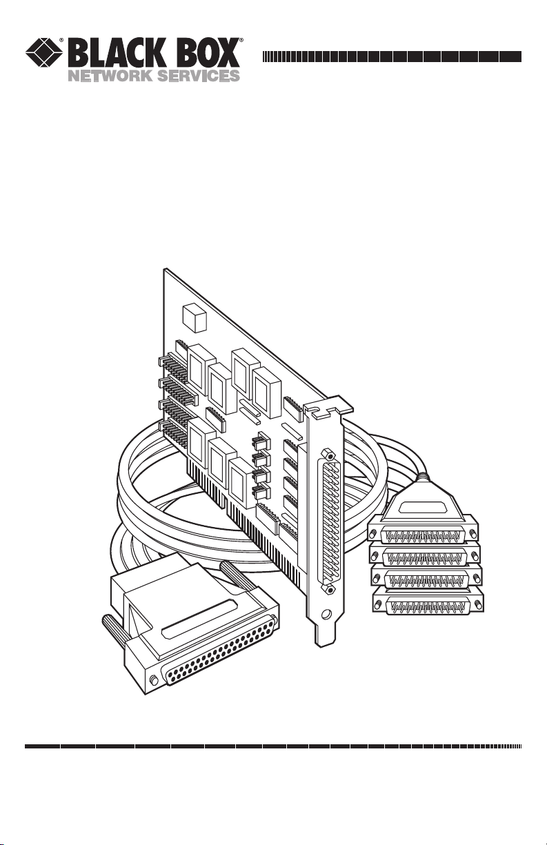
2.2 What’s Included
The Card is shipped with the following items. If any of these items
are missing or damaged, contact the supplier.
• RS-422/485 Serial Interface Plus, 4-Port Card
• DB37 to four DB9 “Spider Cable”
• (2) serial utility software diskettes: (1) for 32-bit Windows®,
(1) for DOS and Windows®3.1x,
• This User’s Manual
2.3 Factory-Default Settings
The factory-default settings are as follows:
Table 2-1. Factory Default Settings.
Port # Base Address IRQ Electrical Specifications
Port 1 3F8 4 RS-422
Port 2 2F8 3 RS-422
Port 3 3E8 4 RS-422
Port 4 2E8 3 RS-422

9
RS-422/485 SERIAL INTERFACE PLUS, 4-PORT
To install the Card using factory-default settings, refer to Chapter 4,
Installation.
For your reference, record installed Card settings below:
Table 2-2. Your Installed Card Settings.
Port # Base Address IRQ Electrical Specifications
Port 1
Port 2
Port 3
Port 4
2.4 Technical Description
The IC058C Card uses the 16750 UART. This chip features programmable
baud rate, data format, and interrupt control, and a 16-byte input and output
FIFO. The IC183C card uses the 16950 UART, which features a 128-byte FIFO
for even better performance.
2.4.1 F
EATURES
• Automatic RS-485 driver enable/disable allows card to appear to be
RS-232, requiring no additional drivers
•“PAL” option allows for unique OEM address selection
• “Shareable” IRQs allow more than one port to share a single IRQ
• IRQs 2/9-7, 10, 11, 12, 15 supported
• 16750 buffered UARTs (IC058C) or 16950 UARTs (IC183C)
• 16 Bit address decode allows for easier integration
• Speeds up to 460.8 kbps available
• Multiple clocking modes ensure compatibility with existing software
products

10
RS-422/485 SERIAL INTERFACE PLUS, 4-PORT
2.4.2 M
ODEM
C
ONTROLSIGNALS
Some software packages require the use of modem handshake signals such as
CTS or DCD. Refer to your application software manual to determine the
requirements for modem control signals. If no requirements are mentioned,
a safe configuration is to tie DTR to DSR and DCD, and tie RTS to CTS. This
configuration will typically satisfy the modem control-signal requirements for
most communications software.
2.4.3 I
NTERRUPTS
A good analogy of a PC interrupt would be a phone ringing. The phone “bell”
is a request for us to stop what we are currently doing and take up another
task (speak to the person on the other end of the line). This is the same
process the PC uses to alert the CPU that a task must be performed. The CPU,
upon receiving an interrupt, makes a record of what the processor was doing
at the time and stores the information in the “stack”; this allows the processor
to resume its predefined duties after the interrupt is handled, exactly where it
left off. Every main subsystem in the PC has its own interrupt, frequently
called an IRQ (short for Interrupt ReQuest).
2.4.4 WHYU
SE AN
ISP?
An Interrupt Status Port (ISP) is a read-only, 8-bit register that sets a
corresponding bit when an interrupt is pending. Port 1 interrupt line
corresponds with Bit D0 of the status port, Port 2 with D1, etc. The use of this
port means that the software designer now only has to poll a single port to
determine if an interrupt is pending.
The ISP is at Base+7 on each port (Example: Base=280 Hex, Status
Port=287, 28F...etc.). The RS-422/485 Serial Interface Plus Card will allow any
one of the available locations to be read to obtain the value in the status port.
All four status ports on the Card are identical, so any one of the four can be
read.
Example: This indicates that Port 2 has an interrupt pending.
Bit Position: 76543210
Value Read: 0000001 0

11
RS-422/485 SERIAL INTERFACE PLUS, 4-PORT
3. Card Setup
The RS-422/485 Serial Interface Plus, 4-Port Card has several jumper straps
which must be set for proper operation.
3.1 Address Selection
Each port on the Card occupies eight consecutive I/O locations. A DIP switch
is used to set the base address for these locations. The Card has a unique
addressing scheme that allows it to be completely compatible with older four
port RS-422/485 interface adapters and provide for the ability to select
address combinations more commonly used.
The first addressing scheme allows the Card to select the addresses for its
ports from a table of available address combinations.
Table 3-1 shows the addressing combinations available. If different address
combinations are required, please contact Technical Support about a custom
PAL option.

12
RS-422/485 SERIAL INTERFACE PLUS, 4-PORT
Table 3-1. Available Address Combinations.
Switch 6 Switch 7 Switch 8 Port 1 Port 2 Port 3 Port 4
On On Off 3F8 2F8 3E8 2E8
On Off On 2F8 3E8 2E8 2E0
On Off Off 3E8 2E8 280 288
Off On On 500 508 510 518
Off On Off 580 588 590 598
Off Off On 1500 1508 1510 1518
Off Off Off 3220 3228 4220 4228
On On On Addresses set up by switches 1-5
NOTE
Each COM: port in the system should have a unique address. Typically COM 1: COM4: addresses are 3F8, 2F8, 3E8, and 2E8 Hex.
Refer to Chapter 5 for common address contentions.
The second mode of address selection provides the compatibility mode. In
this mode, the DIP switch sets the base address and the adapter occupies 32
consecutive I/O locations. Table 3-2 describes the location of each port and
its relationship to the other ports.
NOTE
For switches 1-5 to become active, switches 6, 7, and 8 must be set in the “On” or
“Up” position.
 Loading...