

Page 1
CUSTOMER
SUPPORT
INFORMATION
Order toll-free in the U.S. 24 hours, 7 A.M. Monday to midnight Friday: 877-877-BBOX
FREE technical support, 24 hours a day, 7 days a week: Call 724-746-5500 or fax 724-746-0746
Mail order: Black Box Corporation, 1000 Park Drive, Lawrence, PA 15055-1018
Web site: www.blackbox.com • E-mail: [email protected]
JUNE 2000
IC600C
IC173C
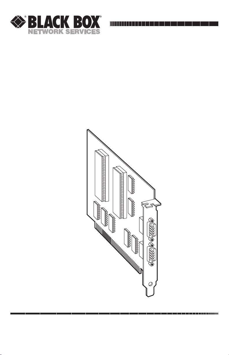
Dual Port RS-422/485
Serial Interface
Page 2

3
FEDERAL COMMUNICATIONS COMMISSION AND INDUSTRY CANADA
RADIO-FREQUENCY INTERFERENCE STATEMENTS
This equipment generates, uses, and can radiate radio-frequency energy
and if not installed and used properly, that is, in strict accordance with the
manufacturer’s instructions, may cause interference to radio communication.
It has been tested and found to comply with the limits for a Class A
computing device in accordance with the specifications in Subpart J of Part 15
of FCC rules, which are designed to provide reasonable protection against
such interference when the equipment is operated in a commercial
environment. Operation of this equipment in a residential area is likely to
cause interference, in which case the user at his own expense will be required
to take whatever measures may be necessary to correct the interference.
Changes or modifications not expressly approved by the party responsible for
compliance could void the user’s authority to operate the equipment.
This digital apparatus does not exceed the Class A limits for radio noise emission from
digital apparatus set out in the Radio Interference Regulation of Industry Canada.
Le présent appareil numérique n’émet pas de bruits radioélectriques dépassant les limites
applicables aux appareils numériques de classe A prescrites dans le Règlement sur le
brouillage radioélectrique publié par Industrie Canada.
TRADEMARKS USED IN THIS MANUAL
PS/2 is a registered trademark of IBM Corporation.
UL is a registered trademark of Underwriters Laboratories Incorporated.
Any other trademarks mentioned in this manual are acknowledged to be the property of
the trademark owners.
FCC AND IC STATEMENTS, TRADEMARKS
Page 3

4
DUAL PORT RS-422/485 SERIAL INTERFACE
NORMAS OFICIALES MEXICANAS (NOM)
ELECTRICAL SAFETY STATEMENT
INSTRUCCIONES DE SEGURIDAD
1. Todas las instrucciones de seguridad y operación deberán ser leídas antes
de que el aparato eléctrico sea operado.
2. Las instrucciones de seguridad y operación deberán ser guardadas para
referencia futura.
3. Todas las advertencias en el aparato eléctrico y en sus instrucciones de
operación deben ser respetadas.
4. Todas las instrucciones de operación y uso deben ser seguidas.
5. El aparato eléctrico no deberá ser usado cerca del agua—por ejemplo,
cerca de la tina de baño, lavabo, sótano mojado o cerca de una alberca,
etc..
6. El aparato eléctrico debe ser usado únicamente con carritos o pedestales
que sean recomendados por el fabricante.
7. El aparato eléctrico debe ser montado a la pared o al techo sólo como
sea recomendado por el fabricante.
8. Servicio—El usuario no debe intentar dar servicio al equipo eléctrico más
allá a lo descrito en las instrucciones de operación. Todo otro servicio
deberá ser referido a personal de servicio calificado.
9. El aparato eléctrico debe ser situado de tal manera que su posición no
interfiera su uso. La colocación del aparato eléctrico sobre una cama,
sofá, alfombra o superficie similar puede bloquea la ventilación, no se
debe colocar en libreros o gabinetes que impidan el flujo de aire por los
orificios de ventilación.
10. El equipo eléctrico deber ser situado fuera del alcance de fuentes de
calor como radiadores, registros de calor, estufas u otros aparatos
(incluyendo amplificadores) que producen calor.
Page 4

5
NOM STATEMENT
11. El aparato eléctrico deberá ser connectado a una fuente de poder sólo
del tipo descrito en el instructivo de operación, o como se indique en el
aparato.
12. Precaución debe ser tomada de tal manera que la tierra fisica y la
polarización del equipo no sea eliminada.
13. Los cables de la fuente de poder deben ser guiados de tal manera que no
sean pisados ni pellizcados por objetos colocados sobre o contra ellos,
poniendo particular atención a los contactos y receptáculos donde salen
del aparato.
14. El equipo eléctrico debe ser limpiado únicamente de acuerdo a las
recomendaciones del fabricante.
15. En caso de existir, una antena externa deberá ser localizada lejos de las
lineas de energia.
16. El cable de corriente deberá ser desconectado del cuando el equipo no
sea usado por un largo periodo de tiempo.
17. Cuidado debe ser tomado de tal manera que objectos liquidos no sean
derramados sobre la cubierta u orificios de ventilación.
18. Servicio por personal calificado deberá ser provisto cuando:
A: El cable de poder o el contacto ha sido dañado; u
B: Objectos han caído o líquido ha sido derramado dentro del
aparato; o
C: El aparato ha sido expuesto a la lluvia; o
D: El aparato parece no operar normalmente o muestra un cambio en su
desempeño; o
E: El aparato ha sido tirado o su cubierta ha sido dañada.
Page 5

6
DUAL PORT RS-422/485 SERIAL INTERFACE
Chapter Page
1. Specifications...................................................................................................7
2. Introduction ....................................................................................................9
2.1 Description.........................................................................................9
2.2 Features ..............................................................................................9
2.3 RS-422/485 Specifications...............................................................10
3. Address Selection ..........................................................................................12
4. Option Selections..........................................................................................14
4.1 E1 and E2 .........................................................................................14
4.2 E3 and E4 .........................................................................................15
5. Interface Options ..........................................................................................16
5.1 Line Termination ............................................................................16
5.2 Oscillator Option.............................................................................16
6. Installation.....................................................................................................17
7. Troubleshooting............................................................................................19
Appendix A. Block Diagram ..............................................................................21
Appendix B. Async Communications................................................................22
Table of Contents
Page 6

7
CHAPTER 1: Specifications
Number of Ports — Dual-port RS-422/485
Maximum Data Distance — Up to 5000 feet (1524 m)
Speed — 115.2 Kbps (RS-422/485); Maximum data
rate depends on software, CPU, and cable
length
Protocol — Asynchronous only
Connectors — (2) DB9 male
Communications Chip — IC600C: 16550 UART;
IC173C: 16850 UART
System Requirements — ISA bus
Operating Temperature — 32 to 122°F (0 to 50°C)
Storage Temperature — –4 to +158°F (–20 to +70°C)
Relative Humidity — 90%
MTBF — > 150,000 hours
MTTR — < 0.25 hour
Manufacturing — IPC 610-A Class-III standards adhered to
with a 0.1 visual A.Q.L. and 100%
Functional Testing; Boards are built to UL
®
94V0 rating and are 100% electrically
tested. Most boards are solder mask over
bare copper or tin nickel.
1. Specifications
Page 7
8
DUAL PORT RS-422/485 SERIAL INTERFACE
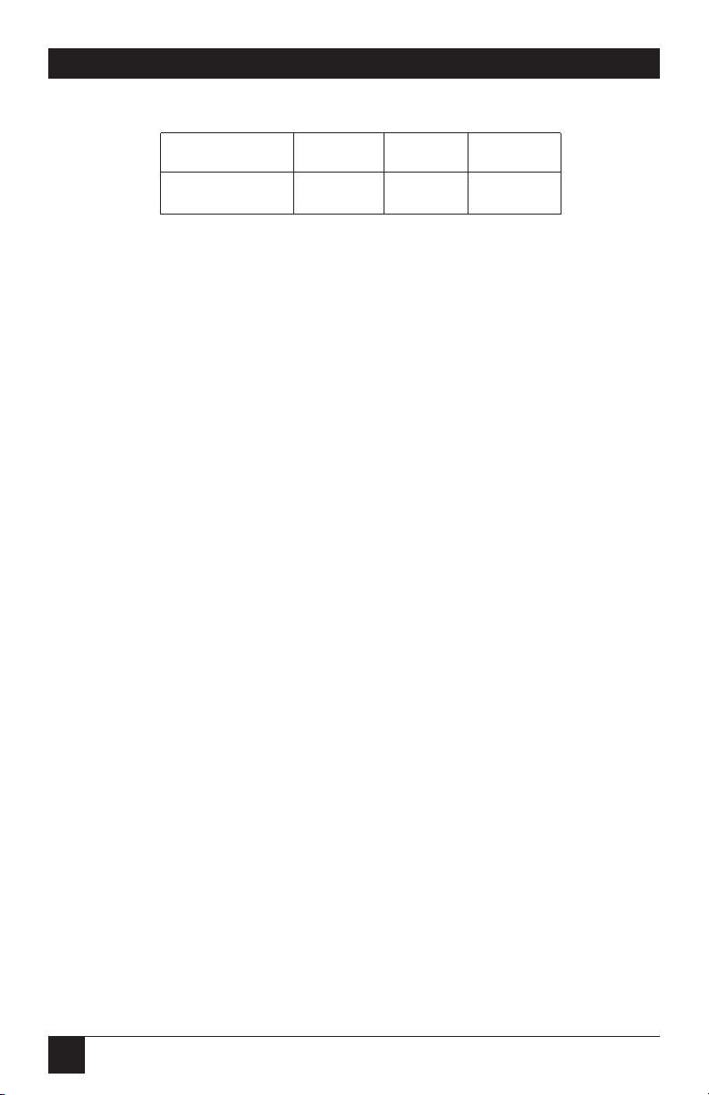
Power —
Supply Line +5 VDC +12 VDC -12 VDC
Rating (mA) 195 mA 25 mA 25 mA
Board Size — Half card; Board length is approximately
4.6 inches (11.7 cm). The height of the
board measured from the motherboard
edge connector is approximately 4.2 inches
(10.7 cm).
Shipping Weight — 2 lb. (0.9 kg)
Page 8

9
CHAPTER 2: Introduction
2.1 Description
The Dual Port RS-422/485 Serial Interface provides two async serial ports
which can interface to RS-422 or RS-485.
The Dual Port RS-422/485 Serial Interface board (IC600C) utilizes the 16550
UART chip. This chip features programmable baud rate, data format, and
interrupt control, and a 16-byte FIFO. The IC173C features the 16850 UART,
which provides a 128-byte FIFO.
Each serial port can be set as COM1 or as COM2, providing total
compatibility with most communications software and languages. Drivers
and receivers for RS-422/485 are provided on the serial port.
2.2 Features
• Supports RS-422/485 interface connections.
• Directly address up to 64 RS-485 devices right from your PC.
• No additional line driver or converter is needed.
• Each port occupies 8 consecutive I/O locations and has base addressing
that’s user-selectable.
• Multiple cards can share the same IRQ level (2 through 5).
• RTS and CTS control signals provided on both ports.
• Includes self-explaining utility software for diagnostics.
2. Introduction
Page 9

10
DUAL PORT RS-422/485 SERIAL INTERFACE
2.3 RS-422/485 Specifications
RS-422 allows very-long-distance (5000 feet at 9600 bps) communications with
virtually error-free differential drive characteristics. RS-422 is similar to RS-232 in
that it is optimized as a single-node protocol: Typically only one RS-422 device is
connected to a single port. RS-422 signal levels are the standard electrical
specification used in RS-449 and EIA-530. This allows interfacing with equipment
that meets these specifications by using a DB9 to DB37 adapter cable.
RS-485 is backward-compatible with RS-422; however it is optimized for
partyline or multi-drop applications. The output of the RS-422/485 driver is
capable of being active (enabled) or tri-state (disabled). This capability allows
multiple ports to be connected in a multi-drop bus and selectively polled.
Half-duplex two-wire communications are possible by connecting TX+ to RX+
and TX- to RX- in your cable hood. The enable to the driver is connected to
the UART Request To Send (RTS) line for RS-485 communications. This
allows the RS-485 driver to be tri-stated (disabled) when inactive on a multidrop polled network. The software that you are using must know how to
enable the driver when it is answering a poll. Setting this jumper wrong can cause
transmitter contention problems, thus preventing operation by any nodes on the network.
NOTE
To permanently enable the driver (normal RS-422 point-to-point mode),
remove E4 for Port 1 and E3 for Port 2.
Page 10
11
CHAPTER 2: Introduction
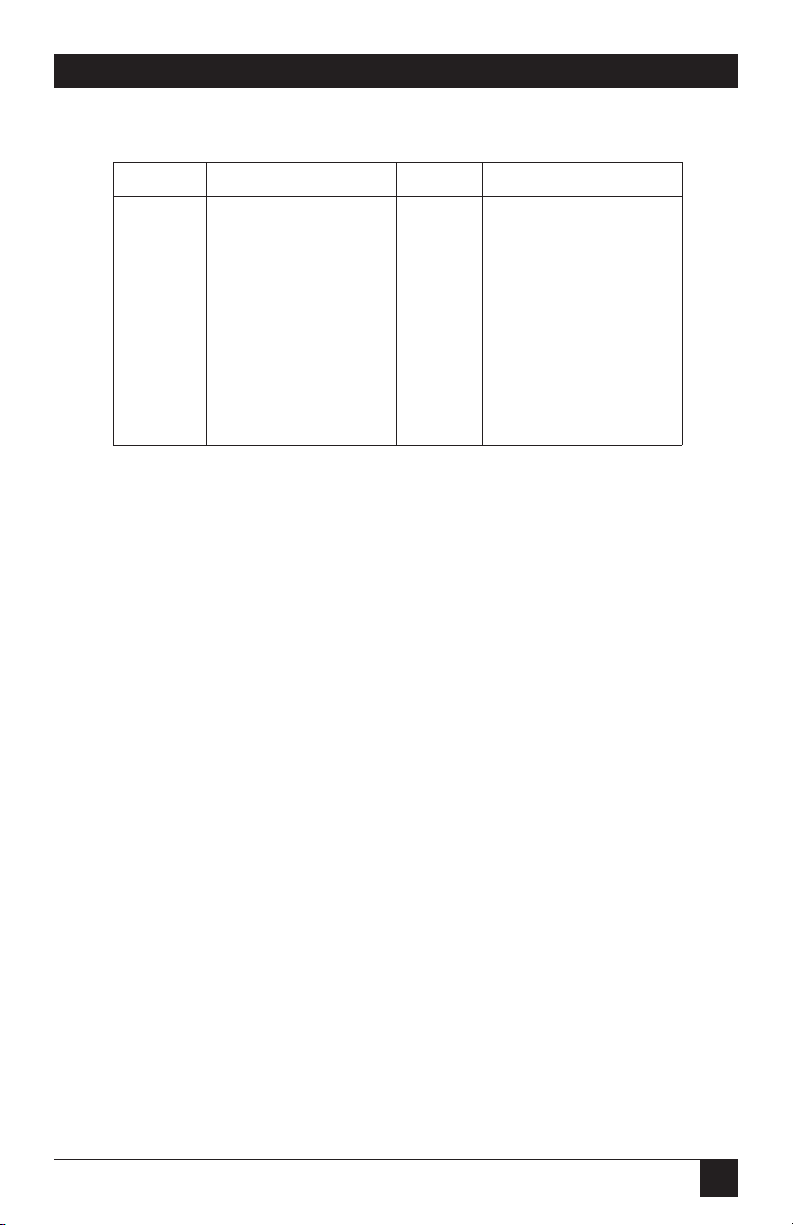
Table 2-1. RS-422/485 Connector Pinouts: (J1 for Port 1, J2 for Port 2)
Signal Name Pin # Mode
TX+ Transmit Data Pos. 4 Output RS-422/485
TX- Transmit Data Neg. 3 Output RS-422/485
RTS+ Req. To Send Pos. 6 Output RS-422/485
RTS- Req. To Send Neg. 7 Output RS-422/485
GND Ground 5
RX+ Receive Data Pos. 1 Input RS-422/485
RX- Receive Data Neg. 2 Input RS-422/485
CTS+ Clear To Send Pos. 9 Input RS-422/485
CTS- Clear To Send Neg. 8 Input RS-422/485
Page 11
12
DUAL PORT RS-422/485 SERIAL INTERFACE
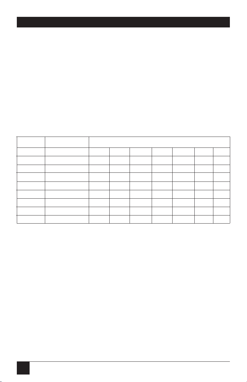
Each serial port on the Dual Port RS-422/485 Serial Interface occupies 8
consecutive I/O locations. DIP-switch S1 is used to set the base address for
Port 1; DIP-switch S2 is used to set the address for Port 2. Be careful when
selecting the base address, since some selections conflict with existing PC
ports. The following table shows several examples that usually do not cause
a conflict.
Table 3-1. Address-Selection Table
Address Binary Switch Position Setting
Hex A9————A0 1 2 3 4 5 6 7
280-287 1010000XXX OFF ON OFF ON ON ON ON
2A0-2A7 1010100XXX OFF ON OFF ON OFF ON ON
2E8-2EF 1011101XXX OFF ON OFF OFF OFF ON OFF
2F8-2FF 1011111XXX OFF ON OFF OFF OFF OFF OFF
3E8-3EF 1111101XXX OFF OFF OFF OFF OFF ON OFF
300-307 1100000XXX OFF OFF ON ON ON ON ON
328-32F 1100101XXX OFF OFF ON ON OFF ON OFF
3F8-3FF 1111111XXX OFF OFF OFF OFF OFF OFF OFF
3. Address Selection
Page 12
13
CHAPTER 3: Address Selection
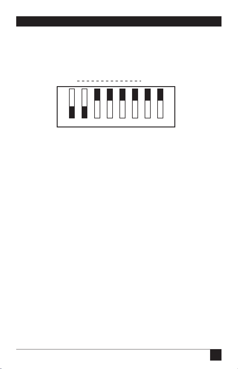
The following illustration shows the correlation between the DIP-switch
setting and the address bits used to determine the base address.
In this example, the address 300 Hex through 307 Hex is selected. 300 Hex
equals 11 0000 0XXX in binary representation.
Note that setting the switch “On” or “Closed” corresponds to a “0” in the
address, while leaving it “Off” or “Open” corresponds to a “1.”
Each port on the Dual Port RS-422/485 Serial Interface can be enabled or
disabled with switch position 8 on the DIP switch. The port is enabled with
the switch “On” or “Closed” and disabled when “Off” or “Open.” If any port
is disabled, be sure to also disable the interrupt request for that port by
removing the IRQ jumper (see Figure 4-1).
A9 A3 EN
ON
12345678
Page 13
14
DUAL PORT RS-422/485 SERIAL INTERFACE
4.1 E1 and E2
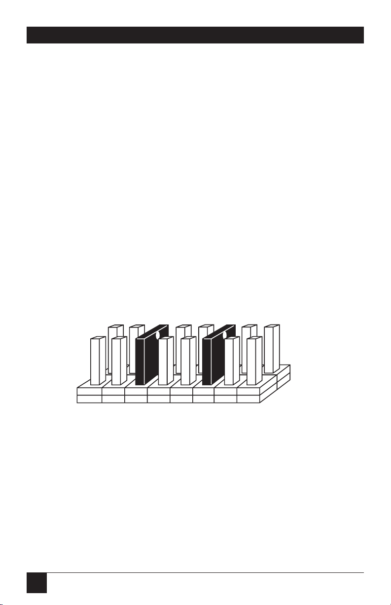
Select the interrupt request for each serial port, E1 for Port 1 and E2 for Port
2. If the address for COM1: is selected, this jumper must be on the IRQ4
setting. If the address for COM2: is selected, this jumper must be on IRQ3.
NOTE
Most communications-software applications default COM3: to IRQ4 and
COM4: to IRQ3. This requires the sharing of interrupts between COM1:
and COM3:, and between COM2: and COM4:. While this is the default, it
is not always the best setting. Check your software’s configuration
instructions to determine the most appropriate IRQ selection.
IMPORTANT
Both ports can be set to the same IRQ, if desired, because of the
interface’s unique open-collector/pull-up IRQ drive circuit. Consult your
particular software for IRQ selection. If no interrupt is desired, remove
this jumper.
Figure 4-1. Header E1 and E2.
4. Option Selections
22334455
E2
E1
Page 14
15
CHAPTER 4: Option Selections
4.2 E3 and E4
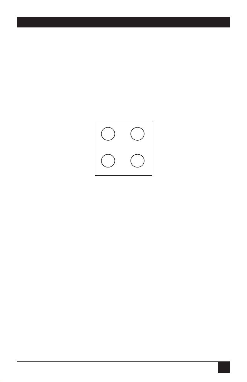
E3 and E4 select whether the RS-485 driver is enabled by the UART signal
Request To Send (RTS) or is always enabled. With the jumper installed, RTS
enables the driver. Removing the jumper enables the driver regardless of
RTS. E3 controls Port 2 while E4 controls Port 1. This jumper should only be
installed if you are running the board in a multi-drop polled environment
such as RS-485. For normal point-to-point RS-422 (such as terminal
emulation), remove this jumper.
Figure 4-2. Header E3 and E4.
E3
E4
2
1
Page 15

16
DUAL PORT RS-422/485 SERIAL INTERFACE
5.1 Line Termination
Typically, each end of the RS-422/485 bus must have line-terminating
resistors. A 100-ohm resistor is across each RS-422/485 input and a 1-Kohm
pull-up/pull-down combination biases the receiver inputs. If multiple (more
than two) RS-485 nodes are configured in a multidrop network, only the
nodes at each end of the bus should have the 100-ohm resistors installed.
5.2 Oscillator Option
If non-standard data rates are required, such as 31.25 Kbps or 76.8 Kbps,
consult your supplier for more information.
5. Interface Options
Page 16

17
CHAPTER 6: Installation
IMPORTANT
You MUST set up the operating system BEFORE you physically install
the Card.
6.1 Software Installation
If you are installing an ISA adapter in DOS, OS/2®, or QNX, please refer to the
appropriate directory on one of the Serial Utilities Disks for instructions.
6.1.1 W
INDOWS
3.1
X
Please refer to the /WINDOWS sub-directory on the Serial Utilities Diskette for
help files and current information on the installation of the Card in this operating
environment.
6.1.2
W
INDOWS
95/98 U
SERS
For the ISA card, run setup on disk two of the Serial Utilities Diskettes before
installing the card. Make note of the resources that Windows assigns the adapter,
and set the adapter to match those resources. Power down the computer and
install the adapter as described in Section 6.2. If you wish to change any resources
assigned to the adapter, refer to the help file installed in the Black Box folder in
the Start, Programs menu.
6.1.3 W
INDOWS
NT
For the ISA card, run setup on disk two of the Serial Utilities Diskettes before
installing the card. After installing the software, refer to the help file that
automatically comes up for installation instructions.
6. Installation
Page 17

18
DUAL PORT RS-422/485 SERIAL INTERFACE
6.2 Hardware Installation
The Dual Port RS-422/485 Serial Interface can be installed in any of the PC
expansion slots.
To install the card:
•Turn off the PC’s power. Disconnect the power cord.
•Remove the PC case.
•Remove the screw holding the blank metal slot cover.
•Remove the blank metal slot cover.
•Gently insert the board. Make sure it is seated properly.
•Replace the blank metal slot cover.
•Replace the screw.
•Replace the PC case.
•Reconnect the power cord.
The installation is complete.
Page 18

19
CHAPTER 7: Troubleshooting
A serial utility diskette is supplied with the Serial Interface and will be used in
the troubleshooting procedures. By using this diskette and following these
simple steps, most common problems can be eliminated.
• Identify all I/O adapters currently installed in your system. This includes
your on-board serial ports, controller cards, sound cards, etc. The I/O
addresses used by these adapters, as well as the IRQ (if any) should be
identified.
• Configure your Serial Interface so that there is no conflict with currently
installed adapters. No two adapters can occupy the same I/O address.
• Make sure the Interface is using a unique IRQ. While the Interface does
allow the sharing of IRQs, many other adapters (for example, SCSI
adapters and on-board serial ports) do not. The IRQ is typically selected via
an on-board header block. Refer to Chapter 3 for help in choosing an
I/O address and IRQ.
• Make sure that the Serial Interface is securely installed in a motherboard
slot.
• Use the supplied diskette and this manual to verify that the Serial
Interface is configured correctly. The supplied diskette contains a
diagnostic program, SSD, that will verify if an adapter is configured
properly. This diagnostic program is written with the user in mind and is
easy to use. Refer to the README file on the disk for detailed instructions
on using SSD.
• The following are known I/O conflicts:
The 278 and 378 settings may conflict with your printer I/O adapter.
3B0 cannot be used if a monochrome adapter is installed.
3F8-3FF is typically reserved for COM1.
2F8-2FF is typically reserved for COM2.
3E8-3EF is typically reserved for COM3.
2E8-2EF is typically reserved for COM4.
7. Troubleshooting
Page 19

20
DUAL PORT RS-422/485 SERIAL INTERFACE
• Refer to the diskette for any post-production manual updates and
application-specific information.
• Use the diagnostic software when troubleshooting a problem.
Page 20
21
APPENDIX A: Block Diagram
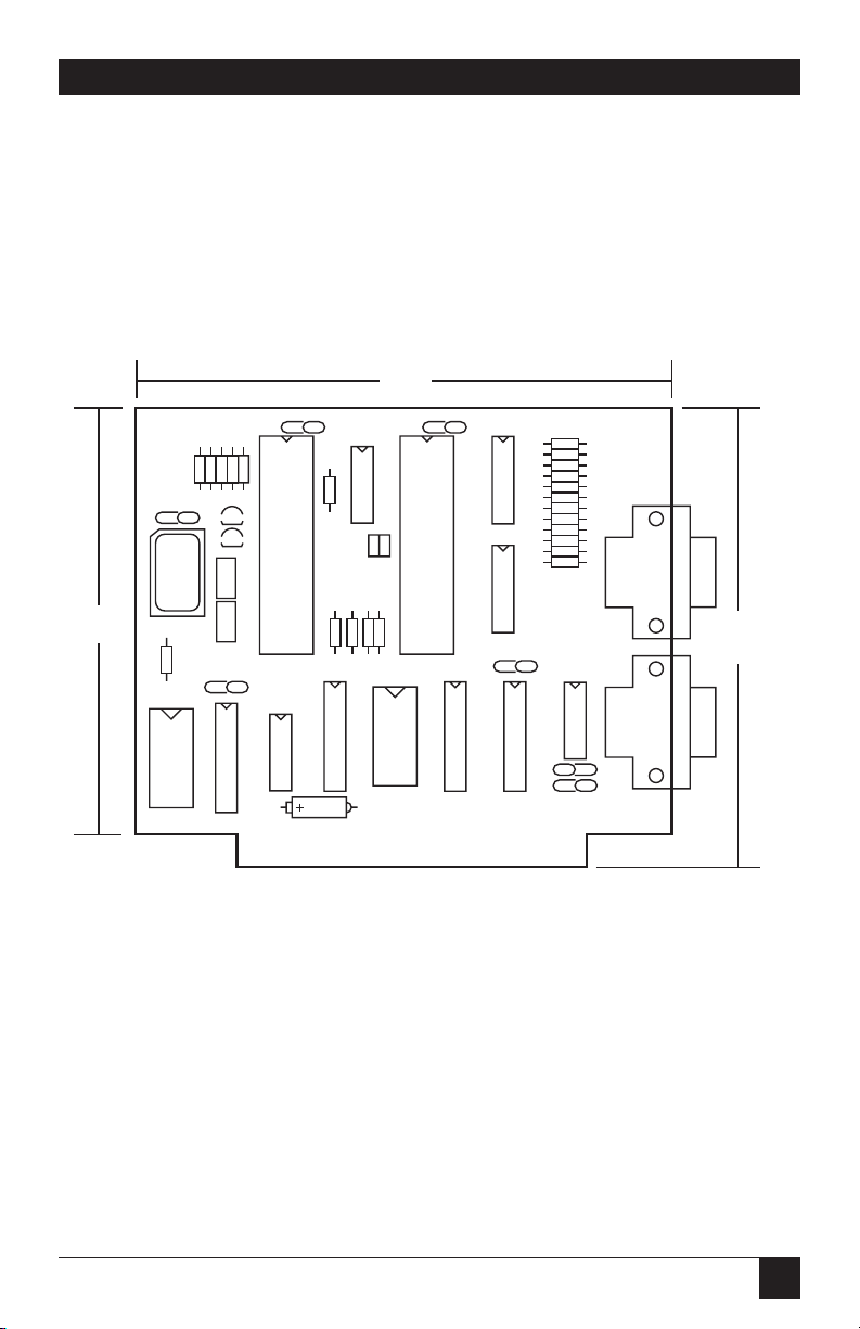
For in-depth schematic detail, call for technical support.
PORT2
PORT1
PORT1
PORT2
S2
S1
E
E
C6
U7
C8
Q2
Q1
E1
E2
2
3
4
5
2
3
4
5
R23
U1
R3R4R2R6R5
U15
U8
C1
C5
U2
R22
R7R9R8
R1
E4
E3
U3
U9
1 2
C4
U4
U5
C7
R10
R12
R21
J1
PORT1
J2
PORT2
R20
R18
R16
R11
R13
R15
R19
R17
R14
U11
U12
U13
C2
C3
5
9
1
6
5
9
1
6
4.6"
4.2"
3.9"
Appendix A: Block Diagram
Page 21
22
DUAL PORT RS-422/485 SERIAL INTERFACE
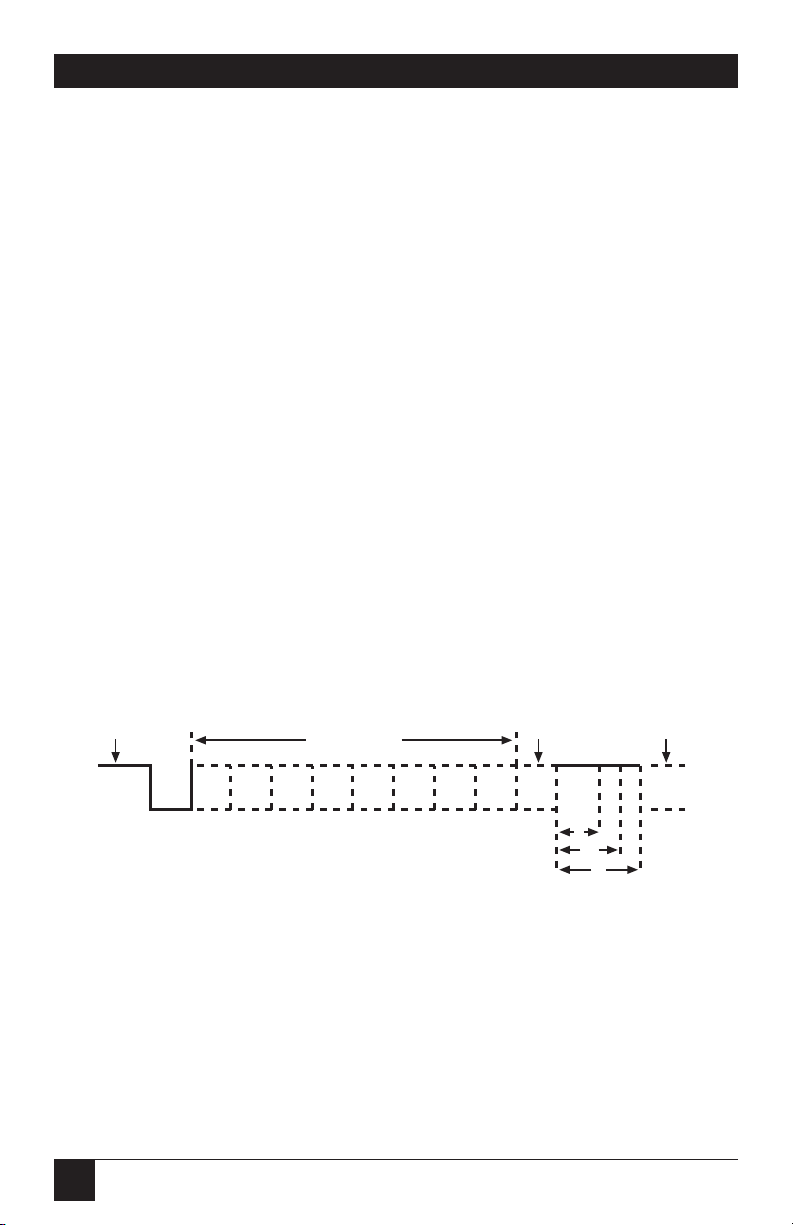
Serial data communications implies that individual bits of a character are
transmitted consecutively to a receiver that assembles the bits back into a
character. Data rate, error checking, handshaking, and character framing
(start/stop bits) are pre-defined and must correspond at both the
transmitting and receiving ends.
Asynchronous communications is the standard means of serial data
communication for PC compatibles and PS/2®computers. The original PC
was equipped with a communication or COM: port that was designed around
an 8250 Universal Asynchronous Receiver Transmitter (UART). This device
allows asynchronous serial data to be transferred through a simple and
straightforward programming interface. Character boundaries for
asynchronous communications are defined by a starting bit followed by a predefined number of data bits (5, 6, 7, or 8). The end of the character is
defined by the transmission of a pre-defined number of stop bits (usually 1,
1.5, or 2).
Figure B-1. Asynchronous Communications Bit Diagram.
Remain idle or
next start bit
Odd, Even
or
Unused
Idle state of
line
5 to 8 Data Bits
1.5
1
2
STOP
P
BIT
1
0
Appendix B: Async Communications
Page 22

23
APPENDIX B: Async Communications
An extra bit used for error detection is often appended before the stop
bits.This special bit is called the parity bit. Parity is the simple method of
determining if a data bit has been lost or corrupted during transmission.
There are several methods for implementing a parity check to guard against
data corruption. Common methods are called even parity (E) or odd parity
(O). Sometimes parity is not used to detect errors on the data stream. This is
referred to as no parity (N).
Because each bit in asynchronous communications is sent consecutively, it is
easy to generalize asynchronous communications by stating that each
character is wrapped (framed) by pre-defined bits to mark the beginning and
end of the serial transmission of the character. The data rate and
communication parameters for asynchronous communications have to be the
same at both the transmitting and receiving ends. The communication
parameters are baud rate, parity, number of data bits per character, and stop
bits (for example, 9600, N, 8, 1).
Page 23

1000 Park Drive • Lawrence, PA 15055-1018 • 724-746-5500 • Fax 724-746-0746
© Copyright 2000. Black Box Corporation. All rights reserved.
 Loading...