


1000 Park Drive • Lawrence, PA 15055-1018 • 724-746-5500 • Fax 724-746-0746
© Copyright 2008. Black Box Corporation. All rights reserved.
AUGUST 2008
IC169A
IC169AE
USB X-Tender
CUSTOMER SUPPORT INFORMATION
Order toll-free in the U.S.: Call 877-877-BBOX (outside U.S. call 724-746-5500)
FREE technical support 24 hours a day, 7 days a week: Call 724-746-5500 or fax 724-746-0746
Mailing address: Black Box Corporation, 1000 Park Drive, Lawrence, PA 15055-1018
Web site: www.blackbox.com • E-mail: info@blackbox.com

1
FCC AND IC STATEMENTS
FEDERAL COMMUNICATIONS COMMISSION AND
INDUSTRY CANADA
RADIO-FREQUENCY INTERFERENCE STATEMENTS
Class B Digital Device. This equipment has been tested and found to comply with
the limits for a Class B computing device pursuant to Part 15 of the FCC Rules.
These limits are designed to provide reasonable protection against harmful
interference in a residential installation. However, there is no guarantee that
interference will not occur in a particular installation. This equipment generates,
uses, and can radiate radio frequency energy, and, if not installed and used in
accordance with the instructions, may cause harmful interference to radio
communications. If this equipment does cause harmful interference to radio or
telephone reception, which can be determined by turning the equipment off
and on, the user is encouraged to try to correct the interference by one of the
following measures:
• Reorient or relocate the receiving antenna.
• Increase the separation between the equipment and receiver.
• Connect the equipment into an outlet on a circuit different from that to
which the receiver is connected.
• Consult an experienced radio/TV technician for help.
Caution:
Changes or modifications not expressly approved by the party responsible for
compliance could void the user’s authority to operate the equipment.
To meet FCC requirements, you must use shielded cables and power cords with
this device. (This includes the CAT5 cable you’ll use to interconnect the Hostand Device-Interface modules.)
This digital apparatus does not exceed the Class A limits for radio noise emission from
digital apparatus set out in the Radio Interference Regulation of Industry Canada.
Le présent appareil numérique n’émet pas de bruits radioélectriques dépassant les limites
applicables aux appareils numériques de classe A prescrites dans le Règlement sur le
brouillage radioélectrique publié par Industrie Canada.

2
USB X-TENDER
EUROPEAN UNION DECLARATION OF CONFORMITY
The USB X-Tender complies with the requirements of the EMC Directive
89/336/EEC. The product was tested in a typical configuration.

3
NOM STATEMENT
NORMAS OFICIALES MEXICANAS (NOM)
ELECTRICAL SAFETY STATEMENT
INSTRUCCIONES DE SEGURIDAD
1. Todas las instrucciones de seguridad y operación deberán ser leídas antes
de que el aparato eléctrico sea operado.
2. Las instrucciones de seguridad y operación deberán ser guardadas para
referencia futura.
3. Todas las advertencias en el aparato eléctrico y en sus instrucciones de
operación deben ser respetadas.
4. Todas las instrucciones de operación y uso deben ser seguidas.
5. El aparato eléctrico no deberá ser usado cerca del agua—por ejemplo,
cerca de la tina de baño, lavabo, sótano mojado o cerca de una alberca,
etc..
6. El aparato eléctrico debe ser usado únicamente con carritos o pedestales
que sean recomendados por el fabricante.
7. El aparato eléctrico debe ser montado a la pared o al techo sólo como sea
recomendado por el fabricante.
8. Servicio—El usuario no debe intentar dar servicio al equipo eléctrico más
allá a lo descrito en las instrucciones de operación. Todo otro servicio
deberá ser referido a personal de servicio calificado.
9. El aparato eléctrico debe ser situado de tal manera que su posición no
interfiera su uso. La colocación del aparato eléctrico sobre una cama,
sofá, alfombra o superficie similar puede bloquea la ventilación, no se
debe colocar en libreros o gabinetes que impidan el flujo de aire por los
orificios de ventilación.

4
USB X-TENDER
10. El equipo eléctrico deber ser situado fuera del alcance de fuentes de calor
como radiadores, registros de calor, estufas u otros aparatos (incluyendo
amplificadores) que producen calor.
11. El aparato eléctrico deberá ser connectado a una fuente de poder sólo del
tipo descrito en el instructivo de operación, o como se indique en el
aparato.
12. Precaución debe ser tomada de tal manera que la tierra fisica y la
polarización del equipo no sea eliminada.
13. Los cables de la fuente de poder deben ser guiados de tal manera que no
sean pisados ni pellizcados por objetos colocados sobre o contra ellos,
poniendo particular atención a los contactos y receptáculos donde salen
del aparato.
14. El equipo eléctrico debe ser limpiado únicamente de acuerdo a las
recomendaciones del fabricante.
15. En caso de existir, una antena externa deberá ser localizada lejos de las
lineas de energia.
16. El cable de corriente deberá ser desconectado del cuando el equipo no
sea usado por un largo periodo de tiempo.
17. Cuidado debe ser tomado de tal manera que objectos liquidos no sean
derramados sobre la cubierta u orificios de ventilación.
18. Servicio por personal calificado deberá ser provisto cuando:
A: El cable de poder o el contacto ha sido dañado; u
B: Objectos han caído o líquido ha sido derramado dentro del
aparato; o
C: El aparato ha sido expuesto a la lluvia; o
D: El aparato parece no operar normalmente o muestra un cambio en
su desempeño; o
E: El aparato ha sido tirado o su cubierta ha sido dañada.

5
TRADEMARKS
TRADEMARKS USED IN THIS MANUAL
BLACK BOX and the logo are registered trademarks of
Black Box Corporation.
Any other trademarks mentioned in this manual are acknowledged
to be the property of the trademark owners.

6
USB X-TENDER
Contents
Chapter Page
1. Specifications .............................................................. 8
2. Introduction ............................................................. 11
3. Configuration ........................................................... 13
4. Installation ................................................................ 15
4.1 Attaching USB Equipment ............................... 15
4.1.1 Applications with a
Single USB Peripheral ........................ 16
4.1.2 Applications with Two USB Peripherals
on Separate Channels ........................ 18
4.1.3 Applications with Multiple
USB Peripherals Connected
Through a Hub.................................... 20
4.2 Attaching CAT5 Cabling ................................... 22
4.3 Attaching Power ................................................ 24
5. Operation .................................................................. 25
6. Troubleshooting ....................................................... 26
6.1 Things to Try ..................................................... 26
6.2 Calling Black Box .............................................. 28
6.3 Shipping and Packaging ................................... 29

7
TABLE OF CONTENTS
Chapter Page
Appendix A: The USB X-Tender’s Connectors ............ 30
Appendix B: Extension-Cable Requirements ................ 32
Appendix C: USB 1.1 Compliance ................................. 35
Appendix D: Device Speeds ........................................... 36
Glossary ............................................................................ 38

8
USB X-TENDER
1. Specifications
Compliance — CE; FCC Class B, IC Class/classe B
Standard — USB 1.1 (see Appendix C)
Interfaces —
Both Modules: Proprietary dual-channel USB composite;
Host-Interface Module: USB Type B;
Device-Interface Module: USB Type A
Data Rate — Up to 12 Mbps on each channel that’s set for
full speed; up to 1.2 Mbps on each channel set for low
speed
Maximum Distance —
USB cable from either Module to attached equipment:
6 ft. (1.8 m) to a computer’s USB port;
9.8 ft. (3 m) to a low-speed device;
16.4 ft. (5 m) to a full-speed device;
Total USB cable and CAT5 cable, end to end (from
computer to farthest peripheral):
150 ft. (45.7 m) if a USB hub or other full-speed
device is attached to the Device-Interface Module;
1000 ft. (304.8 m) if only low-speed devices are
attached to the Device-Interface Module;
For more information, see Appendixes B and D

9
CHAPTER 1: Specifications
User Controls — (2) Rear-mounted DIP switches on each
Module for channel speed
Indicators — None
Connectors —
Both Modules: (1) Front-mounted RJ-45 female for
CAT5 link;
Host-Interface Module: (2) Rear-mounted USB Type B
female for computer/host connection;
Device-Interface Module:
(2) Rear-mounted USB Type A female for
peripheral/hub connection;
(1) Front-mounted 5.5-mm barrel jack for power;
See also Appendix A
Temperature Tolerance —
Operating: 5 to 95˚F (–15 to +35˚C);
Storage: –4 to +140˚F (–20 to +60˚C)
Humidity Tolerance — 20% to 90% noncondensing
Maximum Altitude — 10,000 ft. (3048 m)

10
USB X-TENDER
Power —
Through desktop power supply:
Input: 100 to 240 VAC, 47 to 63 Hz (autosensing);
Output: 9 VDC at up to 2.1 amps;
Consumption: 7.2 watts maximum
Size — 1.1"H x 3.9"W x 3.4"D (2.8 x 9.9 x 8.6 cm); width
does not include bottom flanges
Weight — 1 lb. (0.5 kg)
11
CHAPTER 2: Introduction
2. Introduction
The USB X-Tender is designed to connect computers to
Universal Serial Bus (USB) peripherals across much
longer distances than USB would normally allow: up to
150 ft. (45.7 m) if any high-speed devices are involved,
or up to 1000 ft. (304.8 m) to low-speed devices only.
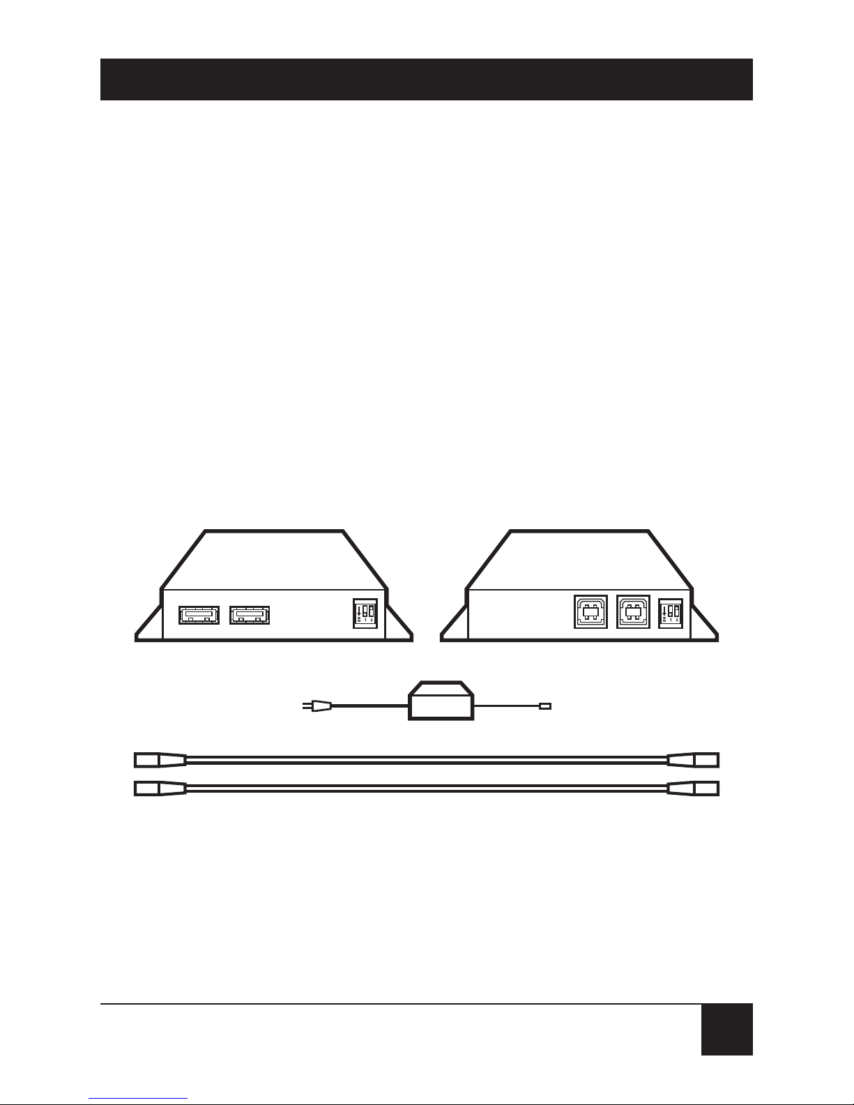
The X-Tender comes from the factory with all of the
components shown in Figure 2-1. If anything is missing
or damaged, call Black Box Technical Support.
Figure 2-1. What you get with the USB X-Tender.
Device-Interface Module Host-Interface Module
Device-Interface Module’s power supply (input cord might not be included)
Two 6-ft. (1.8-m) USB cables

12
USB X-TENDER
The X-Tender comes in two different versions (IC169A
and IC169AE). Both versions include a 100–240-VAC
inline power supply with an IEC 320 C7 connector. The
IC169A includes a U.S. power cord. The IC169AE does
not include a power cord.
The only thing you’ll need to make your USB
X-Tender system work that isn’t included is a Category 5
twisted-pair extension cable that will run between the
Host-Interface Module and the Device-Interface
Module. (See Appendix B for specifications of this
cable.) The maximum distance it can run will be
determined by the types of USB devices you’re using
(see Appendix D): If any of your peripherals are “full
speed,” the total end-to-end cable length (including
both this cable and the USB cables) between the
computer and any peripheral can’t be more than 150 ft.
(45.7 m), but if all of the devices are “low speed,” the
total cable length can be as much as 1000 ft. (304.8 m).

13
CHAPTER 3: Configuration
3. Configuration
Configuring the USB X-Tender is easy, because it only
involves setting one pair of rear-panel DIP switches on
the two Interface Modules, and the settings on both
Modules should be the same.
The USB X-Tender has two independent channels,
“channel 1” and “channel 2.” If you’re only connecting a
single USB device to the host computer, or if you’re
connecting a USB hub to the computer, you’ll only need
to use channel 1. But if you’re connecting a pair of nonhub devices, you’ll need to use both channels.
As shown in Figure 3-1 on the next page, DIP switch 1
applies to channel 1 and DIP switch 2 is for channel 2. If
you’ll be attaching a full-speed USB device (including a
USB hub) to one of the channels, leave that channel’s
switch set to OFF (up) on both Modules. If you’ll only be
attaching a single low-speed device to a channel, move
that channel’s switch to ON (down) on both Modules.
If you set the two channels differently because you’ll
have a full-speed device on one channel and a low-speed
device on the other, make sure that you connect the
devices to the correct channel when you actually install
your system.

14
USB X-TENDER
Figure 3-1. The channel-speed DIP switches.
Host-Interface Module
Affects channel 1
UP (OFF) =
Full speed
DOWN (ON) =
Low speed
Affects channel 2
Device-Interface Module

15
CHAPTER 4: Installation
4. Installation
4.1 Attaching USB Equipment
NOTES
For more information about the USB X-Tender’s data
connectors, see Appendix A.
Before you attach any USB peripheral device to the
USB X-Tender’s Device-Interface Module, we strongly
recommend that you plug it directly into the computer that
will be attached to the X-Tender’s Host-Interface Module
and make sure that the device works properly.
The USB X-Tender has two independent USB channels.
You can attach USB equipment to these channels in any
of three ways:
• Connect a single USB device to a single USB-host
port through X-Tender channel 1 (see
Section 4.1.1).
• Connect a pair of USB devices to a pair of USBhost ports through X-Tender channels 1 and 2
(see Section 4.1.2).
• Connect multiple USB devices to a USB hub,
which is in turn connected to a single USB-host
port through X-Tender channel 1 (see
Section 4.1.3).

16
USB X-TENDER
4.1.1 A
PPLICATIONS WITH A
S
INGLE
USB P
ERIPHERAL
Attach the peripheral device to the “channel 1” port on
the rear of the USB X-Tender’s Device-Interface
Module, as shown in Figure 4-1. (If the device has a
nondetachable USB cable, plug the device directly into
the X-Tender. If the device has a USB port only, run one
of the X-Tender’s included USB cables between the
device and the X-Tender.)
Use one of the X-Tender’s included USB cables to
attach one of the host computer’s USB ports to the
“channel 1” port on the rear of the X-Tender’s HostInterface Module.

17
CHAPTER 4: Installation
Figure 4-1. A single-device application.
Host-
Interface
Module
Host computer
Included
USB cable
Category 5 shielded twisted-pair cable
Device cable or
included USB
cable
USB peripheral
Device-
Interface
Module

18
USB X-TENDER
4.1.2 A
PPLICATIONS WITH
T
WO
USB P
ERIPHERALS ON
S
EPARATECHANNELS
This type of installation is particularly useful if you want
to connect a pair of low-speed devices to a computer,
because it will allow you to run your cables across a full
1000 ft. (304.8 m)—which would not be the case if you
connected both devices through a hub. See Section 4.2
and Appendix D.
Attach one peripheral device to each of the channel
ports on the rear of the USB X-Tender’s DeviceInterface Module, as shown in Figure 4-2. (If a device
has a nondetachable USB cable, plug the device directly
into the X-Tender. If a device has a USB port only, run a
standard USB cable—not one of the ones included with
the X-Tender!—between the device and the X-Tender.)
Use both of the X-Tender’s included USB cables to
attach two of the host computer’s USB ports to the
channel ports on the rear of the X-Tender’s HostInterface Module.

19
CHAPTER 4: Installation
Figure 4-2. A dual-device application.
Host-
Interface
Module
Host computer
Included
USB cables
Category 5 shielded twisted-pair cable
Device cables
or other USB
cables
USB peripherals
Device-
Interface
Module

20
USB X-TENDER
4.1.3 A
PPLICATIONS WITH
M
ULTIPLE
USB P
ERIPHERALS
C
ONNECTEDTHROUGH AHUB
Attach the USB hub to the “channel 1” port on the rear
of the USB X-Tender’s Device-Interface Module, as
shown in Figure 4-3. (If the hub has a nondetachable
USB cable, plug the hub directly into the X-Tender. If
the hub has a USB port only, run one of the X-Tender’s
included USB cables between the hub and the
X-Tender.)
Use one of the X-Tender’s included USB cables to
attach one of the host computer’s USB ports to the
“channel 1” port on the rear of the X-Tender’s HostInterface Module.

21
CHAPTER 4: Installation
Figure 4-3. An application with multiple devices and a hub.
Host-
Interface
Module
Host computer
Included
USB cable
Category 5 shielded twisted-pair cable
USB peripherals
USB hub
Device-
Interface
Module
Device cable
or included
USB cable
Device cables
or other USB
cables

22
USB X-TENDER
4.2 Attaching CAT5 Cabling
If you want to, you can connect the Host-Interface
Module to the Device-Interface Module with a dedicated
Category 5 (CAT5) extension cable. Run this cable
directly from the RJ-45 jack on the front of the HostInterface Module to the matching jack on the front of
the Device-Interface Module.
However, it’s probably more likely that the site or
building in which you’re installing the X-Tender has a
lot of Category 5 (or higher) wiring already installed in
it that you’ll want to use. If this is the case, run patch
cables from the Modules’ RJ-45 jacks to a pair of
interconnected jacks in wiring closets in your site.
(Figure 4-4 on the next page shows an example of such
an installation.) If you’re using both of the USB
X-Tender’s channels, you’ll need all four pairs of wires
in a run of 4-pair cable. If you’re only using channel 1,
you’ll be able to use 2-pair cable, or just pairs 1 and 2 of
a run of 4-pair cable.
In either case, keep in mind that if there are any fullspeed USB devices attached to your system, including
any USB hubs, the total length of CAT5 cable and USB
cable between the computer and any peripheral must
not exceed 150 ft. (45.7 m). But if there are only one or

23
CHAPTER 4: Installation
two low-speed devices attached to your system, the total
cable length can be as much as 1000 ft. (304.8 m). For a
discussion of full-speed versus low-speed devices, see
Appendix D.
For a more detailed description of the necessary
specifications for the CAT5 cable, see Appendix B.
Figure 4-4. A multiple-device installation using existing premise wiring.
Category 5 premise wiring
(four pairs required)
CAT5
patch
cable
CAT5
patch
cable
Host-
Interface
Module
Host computer
Included
USB cables
USB peripherals
Device-
Interface
Module
Device cables
or other USB
cables

24
USB X-TENDER
4.3 Attaching Power
The USB X-Tender’s Host-Interface Module gets all the
power that it needs to operate from the voltage present
on the host computer’s USB port. The Device-Interface
Module, however, requires an AC power source, not
only to operate itself but also to operate any buspowered USB devices that might be attached to it.
Take the X-Tender’s included power-supply
transformer and plug its output cord into the 5.5-mm
barrel jack on the front of the Device-Interface Module.
Both the IC169A and the IC169AE include a 100–
240-VAC inline power supply with an IEC320 C7 male
inlet. The IC169A includes a C7 U.S. power cord; the
IC169AE does not include a power cord.
The Module should power up and begin operating
immediately; it has no ON/OFF switch. Refer to
Chapter 5 for instructions on powering up the rest of
the system.

25
CHAPTER 5: Operation
5. Operation
After you’ve pre-checked your USB equipment and
verified that it works when everything’s directly
connected (see the Note at the start of Section 4.1),
then configured your Modules and installed everything,
you’re ready to power up the system. (At this point, the
X-Tender’s Remote Module should be plugged in and
powered ON, but all devices attached to the X-Tender
should be powered OFF.)
1. Turn ON the host computer attached to the HostInterface Module.
2. Turn ON any powered peripherals attached to the
Device-Interface Module.
The computer should detect the USB peripherals and
the system should then operate transparently, just as if
the X-Tender weren’t even there. If you have any
problems, see Chapter 6.

26
USB X-TENDER
6. Troubleshooting
6.1 Things to Try
If you have any problems operating your USB
peripherals through the USB X-Tender, here are a few
possible solutions you can try:
• Disconnect/reconnect: Your first step should be to
unplug and replug your peripherals one at a time:
first the device on channel 1, then the device (if
there is one) on channel 2. Within a few seconds,
the host computer might recognize the
peripherals.
• Reset the system: If that doesn’t work, reset the
USB X-Tender system by disconnecting the HostInterface Module from the host computer. (If
both channels are being used, disconnect both
USB cables, starting with the channel 1 cable.)
Wait 10 seconds and then reconnect the cables.
This procedure will reset all connections;
hopefully, the peripherals will now work.

27
CHAPTER 6: Troubleshooting
• Check the speed settings: If the reset doesn’t help,
verify that the channel-speed settings are correct
on both the Host-Interface and Device-Interface
Modules (see Chapter 3). If they aren’t, correct
the problem and perform another reset.
• Check the cable: If the speed settings aren’t the
problem, confirm that your cable is not the issue.
If possible, move both X-Tender Modules and the
attached equipment into a single room. Attach the
Modules to each other with a short (not more
than 20 ft./6.1 m), known-good CAT5 cable.
If the system works normally with a short cable,
then the cable you were using is probably either
faulty or too long. The maximum length for this
cable is 150 feet (45.7 m) if there are any fullspeed USB devices attached to the system.
If the system doesn’t work, even with a short
CAT5 cable, try plugging the USB peripherals
directly into the computer. If it still doesn’t work,
either the computer or the peripherals are
malfunctioning. If the equipment does operate
correctly when the X-Tender’s not involved at all,
call Black Box Technical Support.
If none of these procedures solve the problem, call Black
Box Technical Support as described in the next section.

28
USB X-TENDER
6.2 Calling Black Box
If your USB X-Tender seems to be malfunctioning, do
not attempt to alter or repair the unit. It contains no user-
serviceable parts. Call Black Box Technical Support at
724-746-5500; the problem might be solvable over the
phone.
Before you call, make a record of the history of the
problem. We will be able to provide more efficient and
accurate assistance if you have a complete description,
including:
• the nature and duration of the problem;
• when the problem occurs;
• the components involved in the problem;
• any particular application that, when used,
appears to create the problem or make it worse;
and
• the results of any testing you might have already
done.

29
CHAPTER 6: Troubleshooting
6.3 Shipping and Packaging
If you need to transport or ship your USB X-Tender:
• Package it carefully. We recommend that you use
the original container.
• If the shipping is return- or repair-related, include
everything you received with the X-Tender when
you pack it. Contact Black Box to get a Return
Authorization (RA) number.

30
USB X-TENDER
Appendix A:
The USB X-Tender’s Connectors
The USB X-Tender has three different types of data
connectors: USB Type A, USB Type B, and RJ-45.
USB Type A
USB hosts, and the ends of USB cables
that attach to hosts, have Type A
connectors. The USB ports on the
X-Tender’s Device-Interface Module
are Type A female (shown here), just
like those on a host computer. The
cables from USB peripherals have
matching Type A male plugs.
USB Type B
USB peripherals, and the ends of USB
cables that attach to peripherals, have
Type B connectors. The USB ports on
the X-Tender’s Host-Interface Module
are Type B female (shown here), just
like the “To Computer” ports on a
USB hub. The cable from the USB
host computer has a matching Type B
male plug.
Pins
1
2
34
Pins
1
2
34

31
APPENDIX A: The USB X-Tender’s Connectors
The USB cables supplied with the USB X-Tender, like
all USB cables used for normal host↔peripheral
communication, have a Type A plug on one end and a
Type B plug on the other.
Both types of USB connector have four pins, although
the pins are arranged differently. In each case, Pin 1
carries +5 VDC, Pin 2 carries the negative data signal
(“–Data”), Pin 3 carries the positive data signal
(“+Data”), and Pin 4 carries ground.
RJ-45
8-pin RJ-45 connectors are currently
the most widely used connectors in
computer networks, largely because
they’re modular (easy to plug and
unplug) and they’re ideally suited for
use with Category 5 (CAT5) wiring.
The Host-Interface and DeviceInterface Modules both have a single
RJ-45 female jack (shown here); you’ll
run a CAT5 cable terminated with
matching RJ-45 male plugs between
these jacks on the two Modules.
For a pinout of this connector and
the CAT5 cabling, see Appendix B.
Pins
1
8

32
USB X-TENDER
Appendix B:
Extension-Cable Requirements
The extension cabling that you’ll use to interconnect
the USB X-Tender’s Host-Interface and Device-Interface
Modules must be Category 5 solid-core twisted-pair
cable, pinned and paired according to TIA-568A or
(preferably) -568B, terminated with standard RJ-45
plugs. To maintain compliance with FCC Part 15 Class B
regulations, this cable should be shielded. Unshielded
twisted-pair cabling will work, but should only be
considered for commercial environments where
interference is less likely to be a problem.
If you’re using both of the USB X-Tender’s channels,
you’ll need all four pairs of wires in a run of 4-pair cable.
If you’re only using channel 1, you’ll be able to use
2-pair cable, or just pairs 1 and 2 of a run of 4-pair cable.
(Pairs 1 and 2 correspond to pins 1, 2, 3, and 6. These
are the same pins that 10BASE-T uses, so you can use
10BASE-T cable for this purpose. However, under no
circumstances should you ever connect the USB X-Tender
to any 10BASE-T equipment! This could damage the
X-Tender, the attached USB equipment, and your
10BASE-T network!)

33
APPENDIX B: Extension-Cable Requirements
This cable should be pinned “straight through” (Pin 1
on the Host-Interface Module to Pin 1 on the DeviceInterface Module, Pin 2 to Pin 2, and so on). The pinout
of the RJ-45 connectors on the front of the Modules is
shown in Figure B-1 on the next page.
The color-coding of the twisted pairs in standard
TIA-568A and -568B compliant 4-pair CAT-5 cables is
also shown in Figure B-1. This information will be
important if you are using existing premise wiring as an
extension-cabling component. The X-Tender can be
used with cables compliant with either standard, but the
same standard must be used from one end of your
X-Tender cabling to the other.
As noted elsewhere in this manual, the maximum
length of the extension cable is determined by the speed
of the USB peripheral devices that must be supported
(see Appendix D). Full-speed devices such as cameras
and scanners will limit total cable length (including
CAT5 and USB cable) between the computer and any
peripheral to a maximum of 150 ft. (45.7 m). But if
you’re only attaching one or two low-speed devices such
as mice, the total cabling can be as long as 1000 ft.
(304.8 m).

34
USB X-TENDER
Pin Pair TIA-568A TIA-568B X-Tender
Color Color Channel
1 2 White/Green White/Orange 1
2 2 Green/White Orange/White 1
3 3 White/Orange White/Green 1
4 1 Blue/White Blue/White 2
5 1 White/Blue White/Blue 2
6 3 Orange/White Green/White 1
7 4 White/Brown White/Brown 2
8 4 Brown/White Brown/White 2
The cable shield is normally attached to a shielded connector
housing at one end of the cable.
Figure A-1. Pinning of the RJ-45 connectors and pinning/pairing of the
Category 5 cables.
Pins
RJ-45 Female
8 7 6 5 4 3 2 1

35
APPENDIX C: USB 1.1 Compliance
Appendix C: USB 1.1 Compliance
The USB X-Tender is designed to extend the maximum
connection distance between host computers and
peripheral devices that conform to the USB 1.1
specification. This includes simple USB devices such as
mice, cameras, printers and scanners; USB hubs; and
compound USB devices such as keyboards with built-in
hubs.
Under USB 1.1, the maximum connection distance
for a USB device is 5 meters (16.4 feet) for full-speed
devices or 3 meters (9.8 feet) for low-speed devices. It is
also possible to connect up to five USB hubs in a
daisychain configuration to achieve an extended
connection distance of up to 25 meters (82 feet).
Using the USB X-Tender, you can connect any
USB-1.1-compliant device to a host computer with a
USB-1.1-compliant port over an extended distance
without needing to daisychain hubs.

36
USB X-TENDER
Appendix D: Device Speeds
USB devices can communicate at either of two top
speeds. “Low-speed” devices communicate at up to
1.2 Mbps, while “full-speed” devices communicate at up
to 12 Mbps. Manufacturers of USB devices will typically
implement a device as “low-speed” or “full-speed”
depending on what they’re designed to do:
• Low-speed
A mouse, for example, will always be implemented
as a “low-speed device” because it only needs to
communicate the coordinates of a single point or
the status of a few buttons. This can be done easily
at 1.2 Mbps. Most other pointing devices,
including keyboards, touchscreens, trackballs, and
joysticks, will also be implemented as low-speed
devices.
• Full-speed
A video camera, on the other hand, will always be
implemented as a full-speed device, because it
must communicate the status of a large array of
video pixels points up to 30 times each second,
which can easily require 12 Mbps (and strain even
that limit). Other devices that have to send or
receive massive amounts of video, audio, or other
information in real time—including scanners,

37
APPENDIX D: Device Speeds
printers, headsets, microphones, and sound
systems—will also be implemented as full-speed
devices.
There are two other specialized devices that are
always implemented as full-speed devices: USB
hubs and USB “compound devices” such as
keyboards with built-in hubs.
If you are not sure of the speed of your USB device,
consult its manual. If that doesn’t tell you, check with
the device’s manufacturer. You will need this
information to set up the USB X-Tender.

38
USB X-TENDER
Glossary
USB, like most other standards, has its own set of
buzzwords. Here are definitions for a few of them.
USB
The “Universal Serial Bus” communication interface.
USB device
A computer peripheral such as a keyboard, mouse,
printer, scanner, camera, etc., that outputs or inputs
data on USB. A USB hub functions as a “USB device” to
a computer, but as a “USB host” to peripherals.
USB host
A computer or other central piece of equipment with
USB ports to which USB devices can be attached. A USB
hub functions as a “USB host” to peripherals, but as a
“USB device” to a computer.
USB hub
A concentrator that allows one or more USB devices to
be connected to a single USB port on a host. For
example, a 4-port hub can connect up to four USB
devices to one USB-host port. All USB hubs are fullspeed devices “upstream” and support any combination
of full-speed and low-speed devices “downstream.”

39
GLOSSARY
Compound USB device
A compound USB device is a piece of equipment that
includes more than one USB Device or a combination of
USB Device(s) and USB Hub(s). For example, a USB
keyboard that includes a built-in USB Hub is a
compound USB device. Note that compound USB
devices are always full speed on the “upstream” side.
Upstream
Toward the host. Data passed from a device to a host
travels “upstream.”
Downstream
Toward a device. Data passed from a host to a device
travels “downstream.”
Full-speed
Describes a device that communicates with the host at
the full speed of the Universal Serial Bus, up to a
maximum of 12 Megabits per second (12 Mbps).
Low-speed
Describes a device that communicates with the host
using a special low-speed protocol, up to a maximum of
only 1.2 Megabits per second (1.2 Mbps).

NOTES

NOTES

NOTES
 Loading...