

Page 1
NOVEMBER 1998
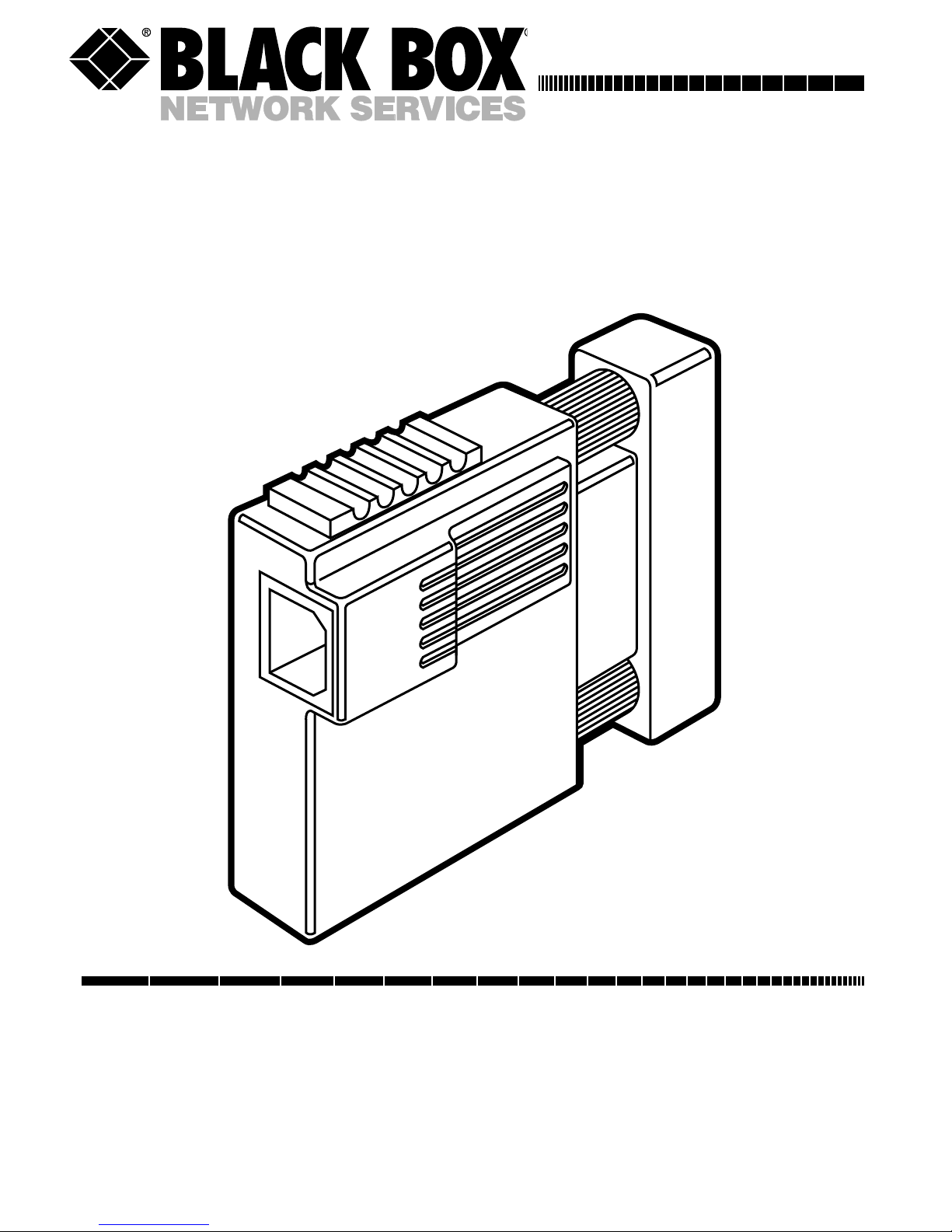
IC138A
USB Solo (USB→Serial)
CUSTOMER SUPPORT INFORMATION
Order toll-free in the U.S.: Call 877-877-BBOX (outside U.S. call 724-746-5500)
FREE technical support 24 hours a day, 7 days a week: Call 724-746-5500 or fax 724-746-0746
Mailing address: Black Box Corporation, 1000 Park Drive, Lawrence, PA 15055-1018
Web site: www.blackbox.com • E-mail: [email protected]
USB SOLO
USB>SERIAL
Page 2

1
FEDERAL COMMUNICATIONS COMMISSION
AND
CANADIAN DEPARTMENT OF COMMUNICATIONS
RADIO FREQUENCY INTERFERENCE STATEMENTS
This equipment generates, uses, and can radiate radio frequency energy and if
not installed and used properly, that is, in strict accordance with the
manufacturer’s instructions, may cause interference to radio communication. It
has been tested and found to comply with the limits for a Class A computing
device in accordance with the specifications in Subpart J of Part 15 of FCC rules,
which are designed to provide reasonable protection against such interference
when the equipment is operated in a commercial environment. Operation of
this equipment in a residential area is likely to cause interference, in which case
the user at his own expense will be required to take whatever measures may be
necessary to correct the interference.
Changes or modifications not expressly approved by the party responsible for
compliance could void the user’s authority to operate the equipment.
This digital apparatus does not exceed the Class A limits for radio noise emission from
digital apparatus set out in the Radio Interference Regulation of the Canadian Department
of Communications.
Le présent appareil numérique n’émet pas de bruits radioélectriques dépassant les limites
applicables aux appareils numériques de classe A prescrites dans le Règlement sur le
brouillage radioélectrique publié par le ministère des Communications du Canada.
Page 3

2
NORMAS OFICIALES MEXICANAS (NOM)
ELECTRICAL SAFETY STATEMENT
INSTRUCCIONES DE SEGURIDAD
1. Todas las instrucciones de seguridad y operación deberán ser leídas antes
de que el aparato eléctrico sea operado.
2. Las instrucciones de seguridad y operación deberán ser guardadas para
referencia futura.
3. Todas las advertencias en el aparato eléctrico y en sus instrucciones de
operación deben ser respetadas.
4. Todas las instrucciones de operación y uso deben ser seguidas.
5. El aparato eléctrico no deberá ser usado cerca del agua—por ejemplo,
cerca de la tina de baño, lavabo, sótano mojado o cerca de una alberca,
etc..
6. El aparato eléctrico debe ser usado únicamente con carritos o pedestales
que sean recomendados por el fabricante.
7. El aparato eléctrico debe ser montado a la pared o al techo sólo como sea
recomendado por el fabricante.
8. Servicio—El usuario no debe intentar dar servicio al equipo eléctrico más
allá a lo descrito en las instrucciones de operación. Todo otro servicio
deberá ser referido a personal de servicio calificado.
9. El aparato eléctrico debe ser situado de tal manera que su posición no
interfiera su uso. La colocación del aparato eléctrico sobre una cama,
sofá, alfombra o superficie similar puede bloquea la ventilación, no se
debe colocar en libreros o gabinetes que impidan el flujo de aire por los
orificios de ventilación.
Page 4

3
10. El equipo eléctrico deber ser situado fuera del alcance de fuentes de calor
como radiadores, registros de calor, estufas u otros aparatos (incluyendo
amplificadores) que producen calor.
11. El aparato eléctrico deberá ser connectado a una fuente de poder sólo del
tipo descrito en el instructivo de operación, o como se indique en el
aparato.
12. Precaución debe ser tomada de tal manera que la tierra fisica y la
polarización del equipo no sea eliminada.
13. Los cables de la fuente de poder deben ser guiados de tal manera que no
sean pisados ni pellizcados por objetos colocados sobre o contra ellos,
poniendo particular atención a los contactos y receptáculos donde salen
del aparato.
14. El equipo eléctrico debe ser limpiado únicamente de acuerdo a las
recomendaciones del fabricante.
15. En caso de existir, una antena externa deberá ser localizada lejos de las
lineas de energia.
16. El cable de corriente deberá ser desconectado del cuando el equipo no
sea usado por un largo periodo de tiempo.
17. Cuidado debe ser tomado de tal manera que objectos liquidos no sean
derramados sobre la cubierta u orificios de ventilación.
18. Servicio por personal calificado deberá ser provisto cuando:
A: El cable de poder o el contacto ha sido dañado; u
B: Objectos han caído o líquido ha sido derramado dentro del
aparato; o
C: El aparato ha sido expuesto a la lluvia; o
D: El aparato parece no operar normalmente o muestra un cambio en
su desempeño; o
E: El aparato ha sido tirado o su cubierta ha sido dañada.
Page 5

4
TRADEMARKS
The trademarks mentioned in this manual are the sole
property of their owners.
Page 6

5
CONTENTS
1. Specifications . . . . . . . . . . . . . . . . . . . . . . . . . . . 6
2. Introduction. . . . . . . . . . . . . . . . . . . . . . . . . . . . 7
2.1 What the Package Includes. . . . . . . . . . . . . 7
2.2 How Does USB Work?. . . . . . . . . . . . . . . . . 7
2.3 System Requirements . . . . . . . . . . . . . . . . . 8
2.4 Other USB Devices You Might Need . . . . . 9
3. Installation . . . . . . . . . . . . . . . . . . . . . . . . . . . . . 10
4. Configuration . . . . . . . . . . . . . . . . . . . . . . . . . . 12
4.1 Assigning COM Ports . . . . . . . . . . . . . . . . . 12
4.2 Changing the COM Port Number . . . . . . . 12
4.3 Deleting a COM Port. . . . . . . . . . . . . . . . . . 13
5. Using the USB Solo. . . . . . . . . . . . . . . . . . . . . . 14
5.1 Power Requirements . . . . . . . . . . . . . . . . . . 15
5.2 Operating Guidelines . . . . . . . . . . . . . . . . . 15
5.3 DOS Support . . . . . . . . . . . . . . . . . . . . . . . . 16
5.4 Mouse Support. . . . . . . . . . . . . . . . . . . . . . . 16
5.5 Typical USB Application . . . . . . . . . . . . . . . 16
Page 7

6
1. Specifications
Access Method—Differential and bidirectional per
USB specification 1.0, 1.5 Mbps low speed
Cable Requirements—USB port: 90 Ω shielded USB
cable (max. 16.4 ft. [5 m]) or unshielded USB
cable (max. 10 ft. [3 m]); RS-232 port: Standard
serial cable
Hardware Requirements—PC that supports USB
Software Requirements—Windows 95 OSR2.x or
Windows 98
Standards—USB 1.0 (for USB low-power device)
CE Approval—Yes
Connectors—(1) USB Type B, (1) RS-232 DB25
male
Power—Self-powered: 0.5 W, 5 VDC, 100 mA max;
Bus: Powered from USB host controller or hub
Size—2.8"H x 2.4"W x 1.3"D (7.1 x 6.1 x 3.3 cm)
Weight—0.4 lb. (0.2 kg)
Page 8

7
2. Introduction
Connect old-style serial peripherals (modems, serial
printers, and so on) to the USB port on your Windows
computer. The USB Solo (USB→Serial) converts the
USB interface to a standard RS-232 serial interface with
an ordinary DB25 connector.
2.1 What the Package Includes
Check to make sure your package includes the following
items. If anything is missing or damaged, please contact
Black Box immediately at 724-746-5500.
• USB Solo (USB→Serial)
• (1) driver diskette
• This user’s manual
2.2 How Does USB Work?
USB uses a unique cable and connector system. The
“upstream” side of the cable (“A” side) connects to a
USB hub or PC. The “downstream” side (“B” side)
connects to USB devices or to another hub’s “A” side.
The USB Solo has a “B” side connector on one side and
Page 9

8
a legacy COM or RS-232 port connector (DB25) on the
other side. It allows you to plug a legacy COM-port
device such as a modem, digital assistant, or printer into
the USB bus.
2.3 System Requirements
The USB Solo requires the following basic host PC
features to operate:
• A host PC that supports the Universal Serial Bus.
• 16 MB of RAM.
• Windows 95 OSR2.x or Windows 98.
You also need to provide the following items:
• (1) standard USB cable
• The serial device to be attached
Page 10

9
2.4 Other USB Devices You Might Need
• Conventional devices without a USB interface
require a USB converter—for example, if your PC
does not have a USB interface, you’ll need the
USB Card (PCI)(part number IC136C).
• To attach more than one device, you will also need
a USB Hub. Choose the USB Director (4- or 7-Port
Hub) (part number IC134A or IC137A) to
connect 4 or 7 USB peripherals.
• Connect 4 high-speed serial devices to one USB
port via the USB Director (USB→RS-232 Hub)
(part number IC135A).
Page 11

10
3. Installation
CAUTION
The USB Solo includes version 2.0 of the drivers. If you
have previously installed USB Solo drivers, then you need
to uninstall the older drivers before continuing. Please view
the README.TXT file on the driver diskette before
continuing.
Follow these steps to install the drivers:
1. Make sure that your system has no other programs
running.
2. Install the driver. Insert the USB Solo driver
diskette into your A: drive. Plug the USB
connection into the serial converter using a
standard USB cable (not supplied). You will see
the Add New Hardware Wizard dialog box. Press
Next. Select “Search for the best driver” and click
Next. Select “Specify a location” and type
“A:\Win95” or
A:\Win98”
and press Next. Verify the
correct driver (A:\Win95\USB2Ser.inf or
A:\Win98\USBS2Ser.inf) and press Next. Click
Finish. Two dialog boxes will appear and install a
USB Serial port. When they disappear, the
installation is complete. Remove the diskette from
your A: drive.
Page 12

11
NOTE
If the Wizard does not appear when you plug in the serial
converter, view the section “Is USB correctly installed?” in
the README.TXT file on the USB Solo driver diskette.
3. A COM port number will then be automatically
assigned as described in “Assigning COM Ports.” If
you need to make any changes to the assigned
COM port, refer to “Changing the COM Port
Number.”
4. Configure your application program to use the
new COM port specified.
5. Plug your legacy serial device into the serial
converter.
NOTE
Although USB devices are “hot plug” capable, RS-232C
devices are not. Always power off the serial device before
either plugging the USB Solo into a USB port or hub or
unplugging it.
Page 13

12
4. Configuration
4.1 Assigning COM Ports
When you first plug a USB Solo into your USB port, it
will use the next available COM-port number. You can
then modify the Options or Properties of your
applications to use the COM port. Standard COM ports
and USB Solo ports share the same COM numbering.
4.2 Changing the COM Port Number
If you need to change the COM-port number assigned
by the system, use the Windows Device manager.
Double-click on My Computer/Control Panel/System
and then pick the Device Manager tab. Go to the entry
for this device and double-click on the entry for the
device you wish to change. Use this dialog box to select a
new COM port, and then click OK. You will then have to
re-configure any applications that used the old COMport number.
Page 14

13
4.3 Deleting a COM Port
To permanently delete a USB Solo from your system’s
configuration, use the Remove button in My
Computer/Control Panel/System/Device Manager after
highlighting the appropriate device. If you plug the
serial converter in again after deleting it, the system will
respond as if it were a new device. The COM port
number may change in this situation.
Page 15

14
5. Using the USB Solo
USB devices support hot-plugging and plug-and-play.
This means that you can re-cable and insert a new device
into your USB network without rebooting or turning
power off. (But you must turn the power off on the
RS-232 device, since RS-232 devices cannot be hotplugged.) When you insert a new USB device, the system
will recognize and configure it automatically. You will
see a popup window verifying that this has occurred.
The USB Solo will appear to the system as a COM
port. The COM number will vary, depending on how
many other COM ports or serial converters you have in
your system. For information on changing the COM
port assignment, see the Configuration section.
Once you have plugged in the USB Solo, first power
off any legacy serial or COM-port device you want to
attach to the system, and then plug it into the DB25
connector. You may need to use a 25-pin to 9-pin
converter or cable if your serial device has a 9-pin
connector. After you have made all the USB
connections, power on the legacy serial or COM port
devices.
Page 16

15
5.1 Power Requirements
USB devices can be either self-powered or bus-powered.
A device that has no power connector is bus-powered,
and derives its operating power from the USB
connection directly. The USB Solo is bus-powered—all
you need to do is plug it into a PC or USB hub.
5.2 Operating Guidelines
After you have installed the driver software and plugged
the USB Solo into the USB port or hub, your new COM
port will be assigned a number. Go to your application’s
setup or options screen and when instructed to pick
from a list of available ports, choose the entry for the
USB Solo (USB→Serial). You can use USB Solos to
attach as many devices as you wish, within system or USB
limits.
NOTE
We have extensively tested the USB Solo with a wide
variety of devices. However, it is impossible to test all of the
legacy serial devices in use today. If you have compatibility
problems, call Black Box Technical Support at 724-746-
5500.
Page 17

16
5.3 DOS Support
This version of the USB Solo drivers provides support
for programs running in a DOS session under Windows.
For additional information about using the DOS Box
support, read the DOSBOX.TXT file on the USB Solo
driver diskette.
5.4 Mouse Support
To use a serial mouse with the USB Solo, just plug in
the mouse and reboot the computer.
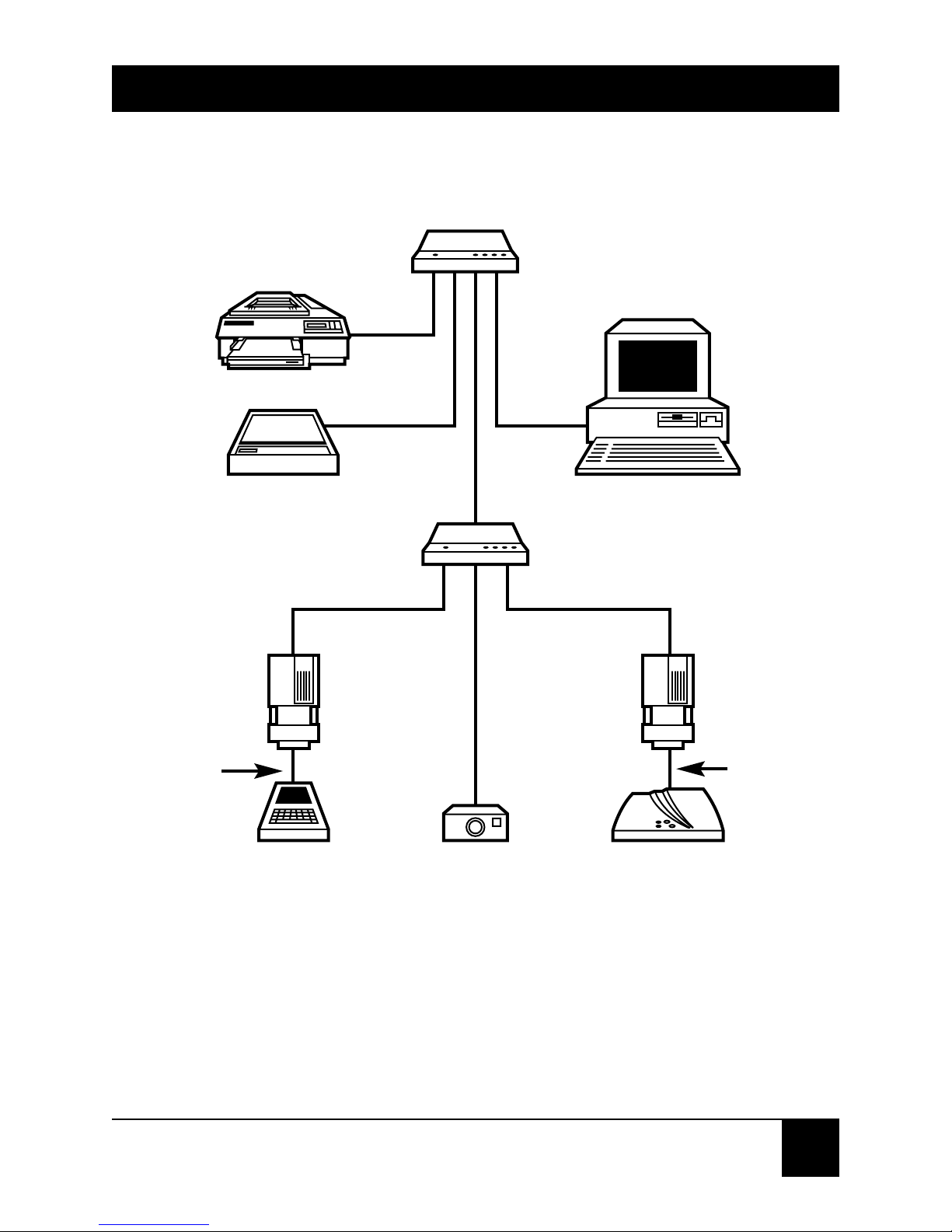
5.5 Typical USB Application
Figure 5-1 shows a typical USB application.
Page 18
17
Figure 5-1. Typical Application.
USB Director (4-Port Hub)
(IC134A)
USB Director (4-Port Hub)
(IC134A)
USB Solo
(IC138A)
Hand-Held
Computer
RS-232 Cable
(ECM25C)
RS-232 Cable
(ECM25C)
Digital
Camera
US Robotics 56K V.90
Voice Faxmodem
(005605)
USB Solo
(IC138A)
Host PC
Printer
Scanner
Page 19
1000 Park Drive • Lawrence, PA 15055-1018 • 724-746-5500 • Fax 724-746-0746
© Copyright 1998. Black Box Corporation. All rights reserved.
 Loading...