

Page 1
CUSTOMER
SUPPORT
INFORMATION
Order toll-free in the U.S.: Call 877-877-BBOX (outside U.S. call 724-746-5500)
FREE technical support 24 hours a day, 7 days a week: Call 724-746-5500 or fax 724-746-0746
Mailing address: Black Box Corporation, 1000 Park Drive, Lawrence, PA 15055-1018
Web site: www.blackbox.com • E-mail: [email protected]
JUNE 2003
IC1023A
IC1024A
IC1025A
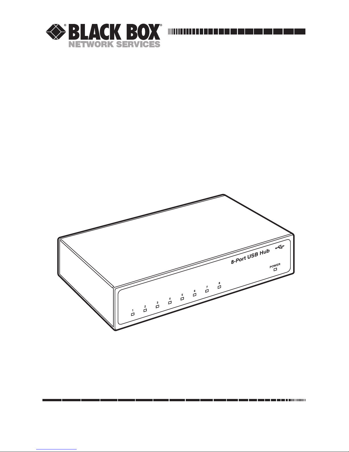
8-Port USB Hub
Page 2

1
FCC AND IC RFI STATEMENTS
FEDERAL COMMUNICATIONS COMMISSION
AND
INDUSTRY CANADA
RADIO FREQUENCY INTERFERENCE STATEMENTS
This equipment generates, uses, and can radiate radio-frequency energy, and if not
installed and used properly, that is, in strict accordance with the manufacturer’s
instructions, may cause interference to radio communication. It has been tested
and found to comply with the limits for a Class A computing device in accordance
with the specifications in Subpart B of Part 15 of FCC rules, which are designed to
provide reasonable protection against such interference when the equipment is
operated in a commercial environment. Operation of this equipment in a
residential area is likely to cause interference, in which case the user at his own
expense will be required to take whatever measures may be necessary to correct
the interference.
Changes or modifications not expressly approved by the party responsible
for compliance could void the user’s authority to operate the equipment.
This digital apparatus does not exceed the Class A limits for radio noise emission from
digital apparatus set out in the Radio Interference Regulation of Industry Canada.
Le présent appareil numérique n’émet pas de bruits radioélectriques dépassant les limites
applicables aux appareils numériques de la classe A prescrites dans le Règlement sur le
brouillage radioélectrique publié par Industrie Canada.
Page 3

2
8-PORT USB HUB
NORMAS OFICIALES MEXICANAS (NOM)
ELECTRICAL SAFETY STATEMENT
INSTRUCCIONES DE SEGURIDAD
1. Todas las instrucciones de seguridad y operación deberán ser leídas antes de
que el aparato eléctrico sea operado.
2. Las instrucciones de seguridad y operación deberán ser guardadas para
referencia futura.
3. Todas las advertencias en el aparato eléctrico y en sus instrucciones de
operación deben ser respetadas.
4. Todas las instrucciones de operación y uso deben ser seguidas.
5. El aparato eléctrico no deberá ser usado cerca del agua—por ejemplo, cerca
de la tina de baño, lavabo, sótano mojado o cerca de una alberca, etc..
6. El aparato eléctrico debe ser usado únicamente con carritos o pedestales que
sean recomendados por el fabricante.
7. El aparato eléctrico debe ser montado a la pared o al techo sólo como sea
recomendado por el fabricante.
8. Servicio—El usuario no debe intentar dar servicio al equipo eléctrico más allá
a lo descrito en las instrucciones de operación. Todo otro servicio deberá ser
referido a personal de servicio calificado.
9. El aparato eléctrico debe ser situado de tal manera que su posición no
interfiera su uso. La colocación del aparato eléctrico sobre una cama, sofá,
alfombra o superficie similar puede bloquea la ventilación, no se debe colocar
en libreros o gabinetes que impidan el flujo de aire por los orificios de
ventilación.
10. El equipo eléctrico deber ser situado fuera del alcance de fuentes de calor
como radiadores, registros de calor, estufas u otros aparatos (incluyendo
amplificadores) que producen calor.
11. El aparato eléctrico deberá ser connectado a una fuente de poder sólo del
tipo descrito en el instructivo de operación, o como se indique en el aparato.
Page 4

3
NOM STATEMENT
12. Precaución debe ser tomada de tal manera que la tierra fisica y la polarización
del equipo no sea eliminada.
13. Los cables de la fuente de poder deben ser guiados de tal manera que no
sean pisados ni pellizcados por objetos colocados sobre o contra ellos,
poniendo particular atención a los contactos y receptáculos donde salen del
aparato.
14. El equipo eléctrico debe ser limpiado únicamente de acuerdo a las
recomendaciones del fabricante.
15. En caso de existir, una antena externa deberá ser localizada lejos de las lineas
de energia.
16. El cable de corriente deberá ser desconectado del cuando el equipo no sea
usado por un largo periodo de tiempo.
17. Cuidado debe ser tomado de tal manera que objectos liquidos no sean
derramados sobre la cubierta u orificios de ventilación.
18. Servicio por personal calificado deberá ser provisto cuando:
A: El cable de poder o el contacto ha sido dañado; u
B: Objectos han caído o líquido ha sido derramado dentro del aparato; o
C: El aparato ha sido expuesto a la lluvia; o
D: El aparato parece no operar normalmente o muestra un cambio en su
desempeño; o
E: El aparato ha sido tirado o su cubierta ha sido dañada.
Page 5

4
8-PORT USB HUB
TRADEMARKS USED IN THIS MANUAL
IBM and PS/2 are registered trademarks of International Business Machines
Corporation.
Windows is either a registered trademark or trademark of Microsoft Corporation
in the United States and/or other countries.
Any other trademarks mentioned in this manual are acknowledged to be the property of the
trademark owners.
Page 6

5
CONTENTS
Contents
Chapter Page
1. Specifications . . . . . . . . . . . . . . . . . . . . . . . . . . . . . . . . . . . . . . . . . . . . . . . . . . 6
2. Introduction . . . . . . . . . . . . . . . . . . . . . . . . . . . . . . . . . . . . . . . . . . . . . . . . . . . 7
2.1 Overview . . . . . . . . . . . . . . . . . . . . . . . . . . . . . . . . . . . . . . . . . . . . . . . . . . 7
2.2 What the Package Includes . . . . . . . . . . . . . . . . . . . . . . . . . . . . . . . . . . . 7
3. Installation . . . . . . . . . . . . . . . . . . . . . . . . . . . . . . . . . . . . . . . . . . . . . . . . . . . . 8
3.1 Installing the Software . . . . . . . . . . . . . . . . . . . . . . . . . . . . . . . . . . . . . . . 8
3.2 System Installation . . . . . . . . . . . . . . . . . . . . . . . . . . . . . . . . . . . . . . . . . . 8
4. Configuration. . . . . . . . . . . . . . . . . . . . . . . . . . . . . . . . . . . . . . . . . . . . . . . . . 10
5. Troubleshooting . . . . . . . . . . . . . . . . . . . . . . . . . . . . . . . . . . . . . . . . . . . . . . 14
5.1 Calling Black Box . . . . . . . . . . . . . . . . . . . . . . . . . . . . . . . . . . . . . . . . . . 14
5.2 Shipping and Packaging . . . . . . . . . . . . . . . . . . . . . . . . . . . . . . . . . . . . 14
Appendix A. Connector Pin Assignments . . . . . . . . . . . . . . . . . . . . . . . . . . . . . . 15
Appendix B. Electrical Interface . . . . . . . . . . . . . . . . . . . . . . . . . . . . . . . . . . . . . 16
B.1 RS-232 . . . . . . . . . . . . . . . . . . . . . . . . . . . . . . . . . . . . . . . . . . . . . . . . . . . 16
B.2 RS-422 . . . . . . . . . . . . . . . . . . . . . . . . . . . . . . . . . . . . . . . . . . . . . . . . . . . 16
B.3 RS-485 . . . . . . . . . . . . . . . . . . . . . . . . . . . . . . . . . . . . . . . . . . . . . . . . . . . 17
Appendix C. Asynchronous Communication . . . . . . . . . . . . . . . . . . . . . . . . . . . 18
Page 7

6
8-PORT USB HUB
1. Specifications
Speed: RS-232: Up to 460.8 kbps; RS-422/485: Up to 921.6 kbps
Standards: USB version 1.1
MTBF: Greater than 150,000 hours
Connectors: (8) DB9 female, (1) USB
Indicators: (9) LEDs: (8) Port activity, (1) Power
Temperature Tolerance: Operating: 32 to 122°F (0 to 50°C);
Storage: -4 to +158°F (-20 to +70°C)
Relative Humidity: Up to 90%, noncondensing
Power: From the USB interface
Size: 2.1"H x 5.9"W x 8.7"D (5.3 x 15 x 22.1 cm)
Page 8

7
CHAPTER 2: Introduction
2. Introduction
2.1 Overview
The 8-Port USB Hub equips the PC with eight USB to asynchronous serial ports.
Use these ports to connect serial devices to your PC; no system resources (I/O
ports or IRQs required)! Models are available with different electrical interfaces:
RS-232 (IC1023A), RS-422/485 (IC1024A), and RS-232/422/485 (IC1025A). All
models are hot-swappable and include LED status indicators for power and port
activity.
The hub has eight USB UARTs. These chips feature programmable baud rate, data
format, 128-byte dual-port TX buffer, and 384-byte dual-port RX buffer. The
RS-232/422/485 transceiver supports data rates up to 921.6 kbps for RS-422/485
and 460.8 kbps for RS-232.
2.2 What the Package Includes
• (1) 8-Port USB Hub
• (1) USB cable for connecting to an upstream host/hub
• (1) CD-ROM with installation software
• This users’ manual
If anything is missing or damaged, please contact Black Box at 724-746-5500.
Page 9

8
8-PORT USB HUB
3. Installation
3.1 Installing the Software
Insert the included CD-ROM into your PC. Choose Install Software, then install
SeaCOM.
3.2 System Installation
The screen captures in this manual are taken from a Windows®98 installation.
Your particular operating system may differ slightly from what is shown based on
your version of Windows.
The 8-Port USB Hub can be connected to any upstream type “A” port, either at
the PC host or an upstream hub. The hub is hot-pluggable, so there’s no need to
power down your computer before installation.
Once you’ve connected the hub to an upstream host or hub, the New Hardware
Found wizard will locate the appropriate drivers. (These drivers were installed
during the SeaCOM software setup procedure.) Once the drivers are found, a new
window will indicate the installation of eight new ports.
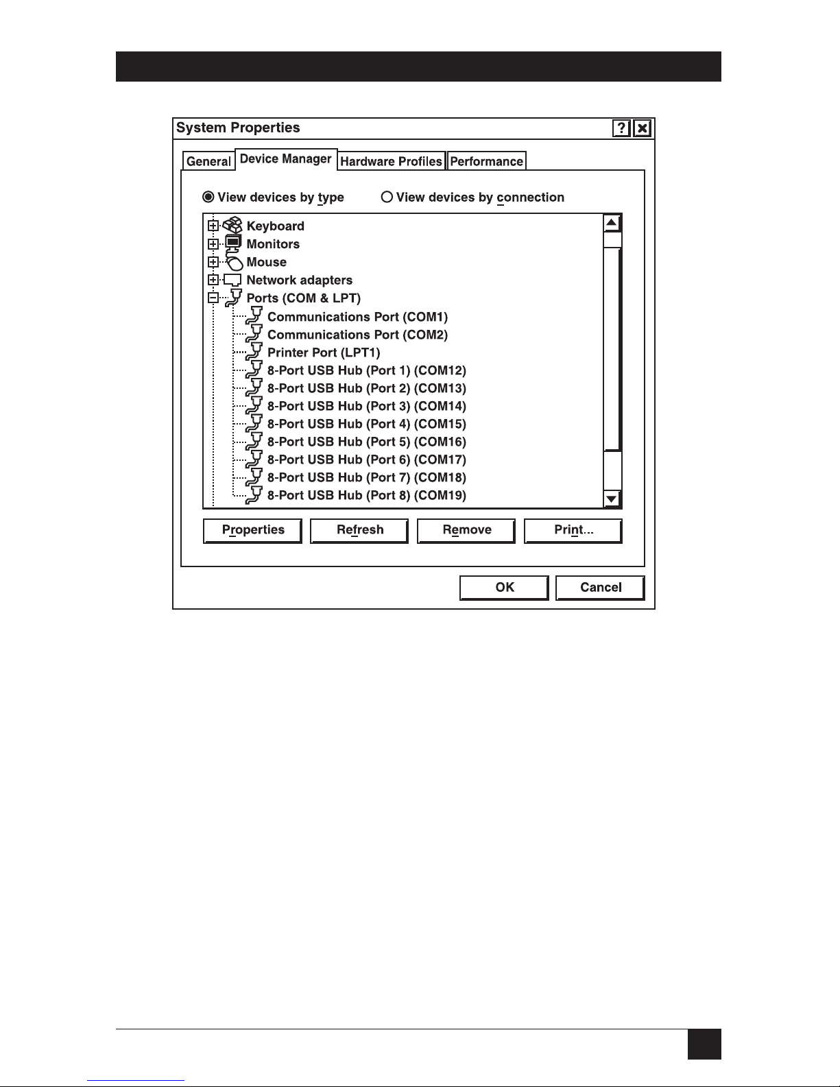
If you view the system’s Device Manager, you should have new COM ports in the
Ports (COM & LPT) Device Class. (See Figure 3-1.)
Page 10
9
CHAPTER 3: Installation
Figure 3-1. System Properties screen, Device Manager tab.
You can access your new COM ports by using the assigned COM identifiers as
shown above (in this case, COM12 through COM19). However, this assignment
will vary from system to system.
At this point, the hardware is recognized and ready to use. Go to Chapter 4 for
configuration information.
Page 11

10
8-PORT USB HUB
4. Configuration
The 8-Port USB Hub arrives with the following configuration:
• IC1023A: Contains no user-configurable components.
• IC1024A and IC1025A: RS-422 4-wire full-duplex mode selected. Transmitter
always enabled. Receiver always enabled and terminated; biased as follows:
120-ohm terminator between RX+ and RX-.
1-Kohm pull-up on RX+.
1-Kohm pull-down on RX-.
To change the configuration on the IC1024A or IC1025A, start by opening the
box. To do this, remove the four screws that attach the two halves of the box.
Each port can be individually configured for the specific electrical interface.
IC1024A supports RS-422/485, and IC1025A supports RS-232/422/485. Select the
interface via the DIP switch associated with each port.
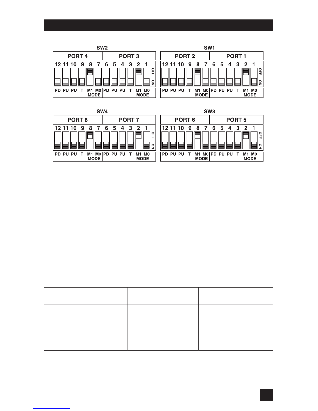
Each DIP switch (SW1, SW2, SW3, and SW4) has a total of 12 positions and
configures two ports. Six positions are designated for each port. The default mode
of RS-422 4-wire full duplex is shown in Figure 4-1.
Page 12
11
CHAPTER 4: Configuration
Figure 4-1. DIP-switches SW1 through SW4 in default mode.
The first two positions for each port (1 and 2 or 7 and 8) are used to select the
electrical interface mode. In RS-422 mode, the transmitter and receiver are always
enabled. “485 WE” refers to RS-485 mode with receiver echo. In this mode, the
receiver is enabled only when no data is being transmitted. “485 NE” refers to
RS-485 mode with no receiver echo. In either RS-485 mode, the transmitter is only
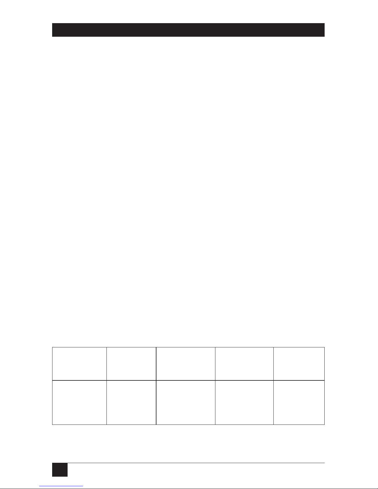
enabled during data transmission. Refer to Table 4-1 for specific switch settings.
NOTE
This chart also appears on the board’s silkscreen.
Table 4-1. Electrical interface mode selection.
Mode M1 (Position 2 or 8) M0 (Position 1 or 7)
232 OFF OFF
422 OFF ON
485 WE ON OFF
485 NE ON ON
Page 13
12
8-PORT USB HUB
The last four positions for each port (3–6 or 9–12) are used to select the line
termination and bias settings. See Table 4-2 for specific switch settings of the three
supported electrical interface modes.
NOTE
This chart also appears on the board’s silkscreen.
PD 1-Kohm pull-down resistor connected to RX-.
(Position RS-232 mode = Always OFF.
6 or 12) RS-422 mode = Always ON.
RS-485 mode = ON if not provided by another device on the bus.
PU 5.1-Kohm pull-up resistor connected to CTS+.
(Position RS-232 mode = Always OFF.
5 or 11) RS-422 mode = Always ON.
RS-485 mode = Always ON.
PU 1-Kohm pull-down resistor connected to RX+.
(Position RS-232 mode = Always OFF.
4 or 10) RS-422 mode = Always ON.
RS-485 mode = ON if not provided by another device on the bus.
T 120-ohm terminating resistor connected between RX+ and RX-.
(Position RS-232 mode = Always OFF.
3 or 9) RS-422 mode = Always ON.
RS-485 mode = ON if physically located at one end of the bus.
Table 4-2. Interface biasing.
Mode PD (Position PU (Position PU (Position T (Position
6 or 12) 5 or 11) 4 or 10) 3 or 9)
232 OFF OFF OFF OFF
422 ON ON ON ON
485 ON ON ON ON*
*If end of 485 bus.
Page 14

13
CHAPTER 4: Configuration
NOTE
There are no provisions for looping TX+ to RX+ and TX- to RX- for 2-wire
RS-485 mode. These connections must be made inside the DB9
connector. Refer to the RS-422 pinout diagram in Appendix A for the
appropriate pin numbers.
Page 15

14
8-PORT USB HUB
5. Troubleshooting
5.1 Calling Black Box
If you determine that your 8-Port USB Hub is malfunctioning, do not attempt to
alter or repair the unit. It contains no user-serviceable parts. Contact Black Box at
724-746-5500.
Before you do, make a record of the history of the problem. We will be able to
provide more efficient and accurate assistance if you have a complete description,
including:
• the nature and duration of the problem.
• when the problem occurs.
• the components involved in the problem.
• any particular application that, when used, appears to create the problem or
make it worse.
5.2 Shipping and Packaging
If you need to transport or ship your 8-Port USB Hub:
• Package it carefully. We recommend that you use the original container.
• If you are shipping the 8-Port USB Hub for repair, make sure you include
everything that came in the original package. Before you ship, contact Black
Box to get a Return Authorization (RA) number.
Page 16

15
APPENDIX A: Connector Pin Assignments
Appendix A. Connector Pin
Assignments
RS-422/485
Table 5-1. RS-422/485 DB9 male.
Signal Name Pin # Mode
GND Ground 5 —
TX+ Transmit Data Positive 4 Output
TX- Transmit Data Negative 3 Output
RTS+ Request to Send Positive 6 Output
RTS- Request to Send Negative 7 Output
RX+ Receive Data Positive 1 Input
RX- Receive Data Negative 2 Input
CTS+ Clear to Send Positive 9 Input
CTS- Clear to Send Negative 8 Input
RS-232
Table 5-2. RS-232 DB9 male.
Signal Name Pin # Mode
GND Ground 5 —
TX Transmit Data 3 Output
RTS Request to Send 7 Output
DTR Data Terminal Ready 4 Output
RX Receive Data 2 Input
CTS Clear to Send 8 Input
DSR Data Set Ready 6 Input
DCD Data Carrier Detect 1 Input
RI Ring Indicator 9 Input
Page 17

16
8-PORT USB HUB
Appendix B. Electrical Interface
B.1 RS-232
Quite possibly the most widely used communication standard is RS-232. This
implementation has been defined and revised several times and is often referred to
as RS-232 or EIA/TIA-232. The IBM
®
PC defined the RS-232 port on a DB9
connector and subsequently the EIA/TIA approved this implementation as the
EIA/TIA-574 standard. This standard is defined as the Data Circuit-Terminating
Equipment Employing Serial Binary Data Interchange. Both implementations are
in widespread use. RS-232 is capable of operating at data rates up to 20 kbps at
distances less than 50 ft. (15.2 m). The absolute maximum data rate may vary due
to line conditions and cable lengths. RS-232 is a single-ended or unbalanced
interface, meaning that a single electrical signal is compared to a common signal
(ground) to determine binary logic states. The RS-232 and the EIA/TIA-574
specification define two types of interface circuits, Data Terminal Equipment
(DTE) and Data Circuit-Terminating Equipment (DCE). The 8-Port USB Hub is a
DTE device.
B.2 RS-422
The RS-422 specification defines the electrical characteristics of balanced voltage
digital interface circuits. RS-422 is a differential interface that defines voltage levels
and driver/receiver electrical specifications. On a differential interface, logic levels
are defined by the difference in voltage between a pair of outputs or inputs. In
contrast, a single-ended interface (for example, RS-232) defines the logic levels as
the difference in voltage between a single signal and a common ground
connection. Differential interfaces are typically more immune to noise or voltage
spikes that may occur on the communication lines. Differential interfaces also have
greater drive capabilities that allows for longer cable lengths. RS-422 is rated up to
10 Mbps and can have cabling 4000 ft. (1219.2 m) long. RS-422 also defines driver
and receiver electrical characteristics that will allow one driver and up to 32
receivers on the line at once. RS-422 signal levels range from 0 to +5 volts. RS-422
does not define a physical connector.
Page 18

17
APPENDIX B: Electrical Interface
B.3 RS-485
RS-485 is backwardly compatible with RS-422; however, it is optimized for party line
or multi-drop applications. The output of the RS-422/485 driver is capable of
being active (enabled) or tri-state (disabled). This capability allows multiple ports
to be connected in a multi-drop bus and selectively polled. RS-485 has electrical
characteristics that allow 32 drivers and 32 receivers to be connected to one line.
This interface is ideal for multi-drop or network environments. RS-485 tri-state
driver (not dual-state) will allow the electrical presence of the driver to be removed
from the line. Only one driver may be active at a time, and the other driver(s) must
be tri-stated. RS-485 can be cabled in two ways: two-wire and four-wire mode. Twowire mode does not allow for full duplex communication and requires that the
data be transferred in only one direction at a time. For half-duplex operation, the
two transmit pins should be connected to the two receive pins (TX+ to RX+ and
TX- to RX-). Four-wire mode allows full duplex data transfers. RS-485 does not
define a connector pinout or a set of modem control signals. RS-485 does not
define a physical connector.
Page 19
18
8-PORT USB HUB
Appendix C. Asynchronous
Communication
Serial data communication implies that individual bits of a character are
transmitted consecutively to a receiver that assembles the bits back into a character.
Data rate, error checking, handshaking, and character framing (start/stop bits) are
pre-defined and must correspond at both the transmitting and receiving ends.
Asynchronous communication is the standard means of serial data communication
for PC compatibles and PS/2
®
computers. The original PC was equipped with a
communication (or COM) port that was designed around an 8250 Universal
Asynchronous Receiver Transmitter (UART). This device allows asynchronous
serial data to be transferred through a simple and straightforward programming
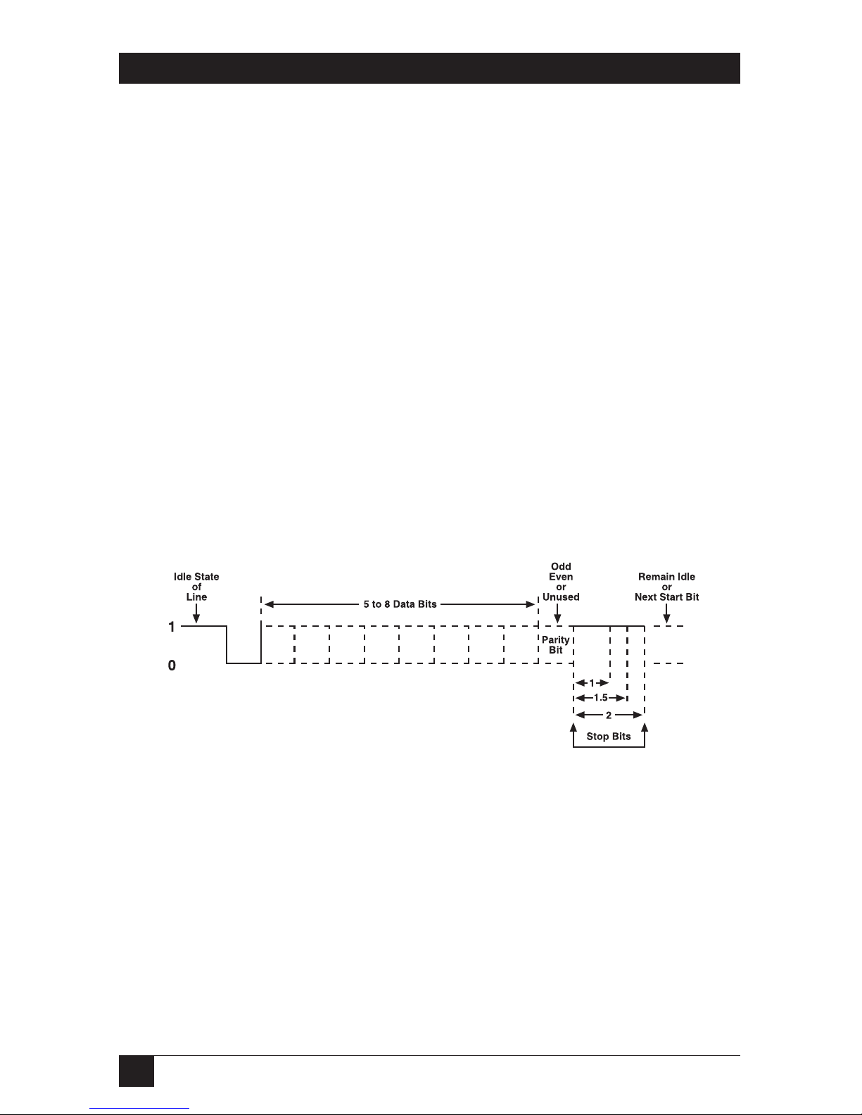
interface. Character boundaries for asynchronous communications are defined by
a starting bit followed by a pre-defined number of data bits (5, 6, 7, or 8). The end
of the character is defined by the transmission of a pre-defined number of stop bits
(usually 1, 1.5, or 2). An extra bit used for error detection is often appended
before the stop bits.
Figure C-1. Asynchronous communication bit diagram.
This special bit is called the parity bit. Parity is a simple method of determining if a
data bit has been lost or corrupted during transmission. There are several methods
for implementing a parity check to guard against data corruption. Common
methods are called (E)ven Parity or (O)dd Parity. Sometimes parity is not used to
detect errors on the data stream. This is referred to as (N)o parity. Because each
bit in asynchronous communication is sent consecutively, it is easy to generalize
asynchronous communication by stating that each character is wrapped (framed)
by pre-defined bits to mark the beginning and end of the serial transmission of the
Page 20

19
APPENDIX C: Asynchronous Communication
character. The data rate and communication parameters for asynchronous
communication have to be the same at both the transmitting and receiving ends.
The communication parameters are baud rate, parity, number of data bits per
character, and stop bits (9600, N, 8, 1).
Page 21

1000 Park Drive • Lawrence, PA 15055-1018 • 724-746-5500 • Fax 724-746-0746
© Copyright 2003. Black Box Corporation. All rights reserved.
 Loading...