

Page 1

1000 Park Drive • Lawrence, PA 15055-1018 • 724-746-5500 • Fax 724-746-0746
© Copyright 2007. Black Box Corporation. All rights reserved.
Page 2
Order toll-free in the U.S.: Call 877-877-BBOX (outside U.S. call 724-746-5500)
FREE technical support 24 hours a day, 7 days a week: Call 724-746-5500 or fax 724-746-0746
Mailing address: Black Box Corporation, 1000 Park Drive, Lawrence, PA 15055-1018
Web site: www.blackbox.com • E-mail: info@blackbox.com
CUSTOMER
SUPPORT
INFORMATION
FEBRUARY 2007
IC027A-R3
488 Controller
Page 3

FCC/IC RFI STATEMENTS
1
FEDERAL COMMUNICATIONS COMMISSION
AND
INDUSTRY CANADA
RADIO FREQUENCY INTERFERENCE STATEMENTS
This equipment generates, uses, and can radiate radio-frequency energy, and if not installed and used
properly, that is, in strict accordance with the manufacturer’s instructions, may cause interference to radio
communication. It has been tested and found to comply with the limits for a Class A computing device in
accordance with the specifications in Subpart B of Part 15 of FCC rules, which are designed to provide reasonable
protection against such interference when the equipment is operated in a commercial environment. Operation of
this equipment in a residential area is likely to cause interference, in which
case the user at his own expense will be required to take whatever measures may be necessary to correct
the interference.
Changes or modifications not expressly approved by the party responsible for compliance could void the user’s
authority to operate the equipment.
This digital apparatus does not exceed the Class A limits for radio noise emission from digital apparatus set out in the Radio
Interference Regulation of Industry Canada.
Le présent appareil numérique n’émet pas de bruits radioélectriques dépassant les limites applicables aux appareils numériques de
la classe A prescrites dans le Règlement sur le brouillage radioélectrique publié par Industrie Canada.
Page 4

488 CONTROLLER
2
INSTRUCCIONES DE SEGURIDAD (Normas Oficiales Mexicanas Electrical Safety Statement)
1. Todas las instrucciones de seguridad y operación deberán ser leídas antes de que el aparato eléctrico sea operado.
2. Las instrucciones de seguridad y operación deberán ser guardadas para referencia futura.
3. Todas las advertencias en el aparato eléctrico y en sus instrucciones de operación deben ser respetadas.
4. Todas las instrucciones de operación y uso deben ser seguidas.
5. El aparato eléctrico no deberá ser usado cerca del agua—por ejemplo, cerca de la tina de baño, lavabo, sótano mojado o
cerca de una alberca, etc..
6. El aparato eléctrico debe ser usado únicamente con carritos o pedestales que sean recomendados por el fabricante.
7. El aparato eléctrico debe ser montado a la pared o al techo sólo como sea recomendado por el fabricante.
8. Servicio—El usuario no debe intentar dar servicio al equipo eléctrico más allá a lo descrito en las instrucciones de
operación. Todo otro servicio deberá ser referido a personal de servicio calificado.
9. El aparato eléctrico debe ser situado de tal manera que su posición no interfiera su uso. La colocación del aparato
eléctrico sobre una cama, sofá, alfombra o superficie similar puede bloquea la ventilación, no se debe colocar en libreros
o gabinetes que impidan el flujo de aire por los orificios de ventilación.
10. El equipo eléctrico deber ser situado fuera del alcance de fuentes de calor como radiadores, registros de calor, estufas u
otros aparatos (incluyendo amplificadores) que producen calor.
11. El aparato eléctrico deberá ser connectado a una fuente de poder sólo del tipo descrito en el instructivo de operación, o
como se indique en el aparato.
12. Precaución debe ser tomada de tal manera que la tierra fisica y la polarización del equipo no sea eliminada.
13. Los cables de la fuente de poder deben ser guiados de tal manera que no sean pisados ni pellizcados por objetos
colocados sobre o contra ellos, poniendo particular atención a los contactos y receptáculos donde salen del aparato.
14. El equipo eléctrico debe ser limpiado únicamente de acuerdo a las recomendaciones del fabricante.
15. En caso de existir, una antena externa deberá ser localizada lejos de las lineas de energia.
16. El cable de corriente deberá ser desconectado del cuando el equipo no sea usado por un largo periodo de tiempo.
17. Cuidado debe ser tomado de tal manera que objectos liquidos no sean derramados sobre la cubierta u orificios de
ventilación.
18. Servicio por personal calificado deberá ser provisto cuando:
A: El cable de poder o el contacto ha sido dañado; u
B: Objectos han caído o líquido ha sido derramado dentro del aparato; o
C: El aparato ha sido expuesto a la lluvia; o
D: El aparato parece no operar normalmente o muestra un cambio en su desempeño; o
E: El aparato ha sido tirado o su cubierta ha sido dañada.
Page 5

3
EUROPEAN UNION DECLARATION OF CONFORMITY
EUROPEAN UNION DECLARATION OF CONFORMITY
To maintain safety, emission, and immunity standards of this declaration, the following conditions must
be met.
• Serial and IEEE cables must have a braided shield connected circumferentially to their connectors’
metal shells.
• All cable screw locks must be tightened at both ends of the cable.
• The host computer must be properly grounded.
• Some inaccuracy is to be expected when I/O leads are exposed to RF fields or transients.
• The operator must observe all safety cautions and operating conditions specified in the documentation
for all hardware used.
• The host computer, peripheral equipment, power sources, and expansion hardware must be CE
compliant.
• All power must be off to the device and externally connected equipment before internal access to the
device is permitted.
• An external power supply is provided with this product. Its input is 100–240 VAC, 50–60 Hz, 0.5 A
maximum power draw. Its 9-VDC, 15 W maximum, 1.7 A output connects to the power input of the unit.
• The RS-232/422 terminal is meant to be connected only to devices with serial-communications-level
signals. The IEEE 488 terminal is meant to be used only with non-isolated IEEE 488 systems. The
common mode voltage (cable shell to earth) must be zero.
• Terminal Installation Category for CE Compliance is Category 1.
• Operating environment for CE compliance is: Indoor use at altitudes below 2000 m, 0 to 40°C, 80%
maximum RH up to 31°C decreasing linearly 4%RH/°C to 40°C.
WARNING!
Noted conditions pertain to potential safety hazards. When you see the WARNING!,
IMPORTANT!, or CAUTION! notes, carefully read the information and be alert to the
possibility of personal injury.
Failure to follow these directives voids emissions and immunity compliance.
Page 6

488 CONTROLLER
4
TRADEMARKS USED IN THIS MANUAL
Macintosh is a registered trademark of Apple Computer, Inc.
BLACK BOX and the Double Diamond logo are registered trademarks of BB Technologies, Inc.
Hewlett-Packard and HP are registered trademarks of Hewlett-Packard.
AT and IBM are registered trademarks of IBM Corporation.
Any other trademarks mentioned in this manual are acknowledged to be the property of the trademark owners.
Page 7

CONTENTS
5
Chapter Page
1. Specifications....................................................................................................................................................8
2. Introduction ...................................................................................................................................................10
2.1 Description............................................................................................................................................10
2.2 What’s Included....................................................................................................................................10
2.3 Abbreviations ........................................................................................................................................11
3. Getting Started ...............................................................................................................................................12
3.1 Configuration .......................................................................................................................................12
3.2 Serial-Port Settings................................................................................................................................14
3.2.1 Serial Baud Rate .......................................................................................................................14
3.2.2 Serial Word Length (Data Bits)...............................................................................................15
3.2.3 Serial Stop Bits .........................................................................................................................16
3.2.4 Serial Parity...............................................................................................................................16
3.2.5 Serial Echo................................................................................................................................17
3.2.6 Serial Handshake .....................................................................................................................17
3.3 Selecting Terminator Substitution.......................................................................................................18
3.3.1 Serial Terminator .....................................................................................................................18
3.3.2 IEEE Bus Terminator...............................................................................................................19
3.4 Selecting the Mode...............................................................................................................................19
3.5 Selecting the IEEE Address..................................................................................................................20
3.6 Feature Selections.................................................................................................................................21
3.6.1 Controller Pass-Thru Features ................................................................................................21
3.6.2 Peripheral Pass-Thru Features ................................................................................................22
3.7 Serial Interface .....................................................................................................................................22
3.7.1 RS-232/RS-422 Signal Level Selection....................................................................................22
3.7.2 Serial Signal Descriptions ........................................................................................................23
3.7.3 Serial-Cable Wiring Diagrams .................................................................................................24
3.8 General Operation ...............................................................................................................................26
3.9 Is Anyone Out There? ..........................................................................................................................27
4. IEEE Operating Modes..................................................................................................................................28
4.1 Introduction..........................................................................................................................................28
4.2 Operating Mode Transitions................................................................................................................28
4.3 System Controller Mode ......................................................................................................................30
4.4 System Controller, Not Active Controller Mode.................................................................................31
4.5 Not System Controller Mode ...............................................................................................................33
4.6 Active Controller, Not System Controller Mode.................................................................................34
4.7 Controller Pass-Thru Mode..................................................................................................................34
4.8 Peripheral Pass-Thru Mode .................................................................................................................34
5. Command Descriptions .................................................................................................................................35
5.1 Introduction..........................................................................................................................................35
5.2 Command-Description Format............................................................................................................36
5.2.1 Syntax........................................................................................................................................36
5.2.2 Response...................................................................................................................................38
5.2.3 Mode .........................................................................................................................................38
5.2.4 Bus States ..................................................................................................................................39
5.3 Memory Use ..........................................................................................................................................40
5.4 The Commands ....................................................................................................................................40
Contents
Page 8

488 CONTROLLER
6
Contents (continued)
Chapter Page
6. Controller Pass-Thru Operation ...................................................................................................................74
6.1 Introduction..........................................................................................................................................74
6.2 Serial and IEEE Terminator Substitution ...........................................................................................74
6.3 IEEE Address Selection ........................................................................................................................75
6.4 Talk Back On Terminator.....................................................................................................................75
6.5 Plotter Applications..............................................................................................................................76
6.6 Printer Applications .............................................................................................................................78
7. Peripheral Pass-Thru Operation ...................................................................................................................79
7.1 Introduction..........................................................................................................................................79
7.2 Serial and IEEE Input Buffers .............................................................................................................79
7.3 IEEE Data Transfers..............................................................................................................................80
7.3.1 Blind Bus Data Transfers .........................................................................................................80
7.3.2 Controlled Bus Data Transfers................................................................................................81
7.4 Serial Poll Status Byte Register ............................................................................................................82
7.5 Use of Serial and Bus Terminators ......................................................................................................83
7.6 IEEE 488 Bus Implementation ............................................................................................................83
7.6.1 My Talk Address (MTA)...........................................................................................................83
7.6.2 My Listen Address (MLA) .......................................................................................................83
7.6.3 Device Clear (DCL and SDC) .................................................................................................84
7.6.4 Interface Clear (IFC)...............................................................................................................84
7.6.5 Serial Poll Enable (SPE) ..........................................................................................................84
7.6.6 Serial Poll Disable (SPD) .........................................................................................................84
7.6.7 Unlisten (UNL)........................................................................................................................84
7.6.8 Untalk (UNT) ..........................................................................................................................84
7.7 IEEE Address Selection ........................................................................................................................84
8. IEEE 488 Primer.............................................................................................................................................85
8.1 History ...................................................................................................................................................85
8.2 General Structure .................................................................................................................................85
8.3 Send It To My Address..........................................................................................................................87
8.4 Bus Management Lines ........................................................................................................................87
8.4.1 Attention (ATN) ......................................................................................................................87
8.4.2 Interface Clear (IFC)...............................................................................................................87
8.4.3 Remote Enable (REN).............................................................................................................87
8.4.4 End or Identify (EOI)..............................................................................................................87
8.4.5 Service Request (SRQ) ............................................................................................................87
8.5 Handshake Lines ..................................................................................................................................88
8.5.1 Data Valid (DAV) .....................................................................................................................88
8.5.2 Not Ready For Data (NRFD) ...................................................................................................88
8.5.3 Not Data Accepted (NDAC)....................................................................................................88
8.6 Data Lines .............................................................................................................................................89
8.7 Multiline Commands............................................................................................................................89
8.7.1 Go To Local (GTL)..................................................................................................................89
8.7.2 Listen Address Group (LAG) ..................................................................................................89
8.7.3 Unlisten (UNL)........................................................................................................................89
8.7.4 Talk Address Group (TAG) .....................................................................................................89
8.7.5 Untalk (UNT) ..........................................................................................................................89
8.7.6 Local Lockout (LLO) ..............................................................................................................89
8.7.7 Device Clear (DCL) .................................................................................................................89
Page 9

CONTENTS
7
Chapter Page
8.7.8 Selected Device Clear (SDC)...................................................................................................89
8.7.9 Serial Poll Disable (SPD) .........................................................................................................89
8.7.10 Serial Poll Enable (SPE) ..........................................................................................................89
8.7.11 Group Execute Trigger (GET)................................................................................................89
8.7.12 Take Control (TCT).................................................................................................................89
8.7.13 Secondary Command Group (SCG).......................................................................................90
8.7.14 Parallel Poll Configure (PPC) .................................................................................................90
8.7.15 Parallel Poll Unconfigure (PPU) ............................................................................................90
8.8 More On Service Requests ...................................................................................................................90
8.8.1 Serial Poll..................................................................................................................................90
8.8.2 Parallel Poll...............................................................................................................................90
9. Theory of Operation & Board Layout ..........................................................................................................91
9.1 Theory of Operation ............................................................................................................................91
9.2 Board Layout.........................................................................................................................................92
Appendix A: 488 Controller Command Summary.............................................................................................94
Appendix B: 488 Controller Error Messages......................................................................................................97
Appendix C: Character Codes and IEEE Multiline Messages ...........................................................................99
Appendix D: Sample Programs .........................................................................................................................101
Page 10

488 CONTROLLER
8
488 Controller
IEEE 488-1978 Implementation: C1, C2, C3, C4, and C28 controller subsets; SH1, AH1, T6,
TE0, L4, LE0, SR1, RL0, PP0, DC1, DT1, E1
Terminators: Selectable CR, LF, LF-CR, and CR-LF with EOI
Connector: Standard IEEE 488 connector with metric studs
Serial Interface
EIA RS-232C: AB, BA, BB, CA, CB
EIA RS-422A: Balanced voltage on TxD and RxD
Character Set: Asynchronous bit serial
Output Voltage: ±5 volts minimum (RS-232C); 3.5 volts typical (RS-422A)
Input Voltage: ±3 volts minimum; ±15 volts maximum
Baud Rate: Selectable 110, 300, 600, 1200, 1800, 2400, 3600, 4800, 7200,
9600, 19,200, and 57,600
Data Format: Selectable 7 or 8 data bits; 1 or 2 stop bits; odd, even, mark,
space and no parity on transmit
Duplex: Full with Echo/No Echo
Serial Control: Selectable CTS/RTS or X-ON/X-OFF
Terminators: Selectable CR, LF, LF-CR, and CR-LF
Connector: DB25; RS-232C DCE configured
1. Specifications
Page 11

9
CHAPTER 1: Specifications
General
Data Buffer: 32,000 characters total, dynamically allocated
Environment: 0 to 50°C; 0 to 70% R.H. to 35°C; Linearly derate
3% R.H./°C from 35 to 50°C
Controls: Power switch (external), IEEE and serial parameter switches
(internal); jumper selection of RS-232 or RS-422 operation
(internal)
Certification: FCC, CE
Indicators: (4) LEDs: Talk, Listen, SRQ, Error, and Power
Power: Input: 100–240 VAC, autosensing, 50–60 Hz,
0.5 A maximum;
Output: 9 V, 15 W maximum, 1.7 A
Size: 2.7"H x 5.5"W x 7.4"D (6.9 x 14 x 18.8 cm)
Weight: 3.6 lb. (1.6 kg)
WARNING!
Do not use this interface outdoors. The interface is intended for indoor use only. Using this
equipment outdoors could result in equipment failure, bodily injury, or death.
CAUTION
Do not connect AC line power directly to the 488 Controller. Direct AC connection will
damage equipment.
Page 12

488 CONTROLLER
10
2.1 Description
The 488 Controller converts a host RS-232 or RS-422 computer into an IEEE 488 bus talker, listener, and
controller. The 488 Controller provides full IEEE 488-1978 bus implementation including advance
capabilities such as PASS CONTROL, RECEIVE CONTROL, PARALLEL POLL, SERIAL POLL, and
SECONDARY ADDRESSING. The device may be located several hundred feet from the host and may
control as many as fourteen 488 bus instruments. In the noncontroller mode the 488 Controller converts
the host into a bus peripheral for data processing and mass storage.
The 488 Controller interprets simple high-level commands sent from the computer’s serial port and
performs the necessary, and usually complex, bus control and handshaking. The commands and protocol
are similar to those used by the Hewlett-Packard
®
HP-85 computer.
Additional features provide a transparent IEEE to serial converter and a serial to IEEE pass-thru controller.
As a serial-to-IEEE-488 converter, the 488 Controller receives data from a serial host, then automatically
performs the bus sequences necessary to send this data to the IEEE 488 device. If desired, data can be
requested from the IEEE 488 device and returned to the host.
As an IEEE-488-to-serial converter, the 488 Controller is a peripheral to an IEEE 488 controller. Data
received from the controller is sent to the serial device and data received from the serial device is buffered
for transmission to the IEEE 488 controller. The 488 Controller can inform the host, by the serial poll-status
byte, that it has received data from the serial device.
2.2 What’s Included
Your package should include the IEEE 488 controller, an AC power cable, and this user’s manual.
2. Introduction
Page 13

11
CHAPTER 2: Introduction
2.3 Abbreviations
The following IEEE 488 abbreviations are used throughout this manual.
addr n IEEE bus address “n”
ATN Attention line
CA Controller Active
CO Controller
CR Carriage Return
data Data String
DCL Device Clear
GET Group Execute Trigger
GTL Go To Local
LA Listener Active
LAG Listen Address Group
LF Line Feed
LLO Local Lock Out
MLA My Listen Address
MTA My Talk Address
PE Peripheral
PPC Parallel Poll Configure
PPU Parallel Poll Unconfigure
REN Remote Enable
SC System Controller
SDC Selected Device Clear
SPD Serial Poll Disable
SPE Serial Poll Enable
SRQ Service Request
TA Talker Active
TAD Talker Address
TCT Take Control
term Terminator
UNL Unlisten
UNT Untalk
* Unasserted
Page 14
488 CONTROLLER
12
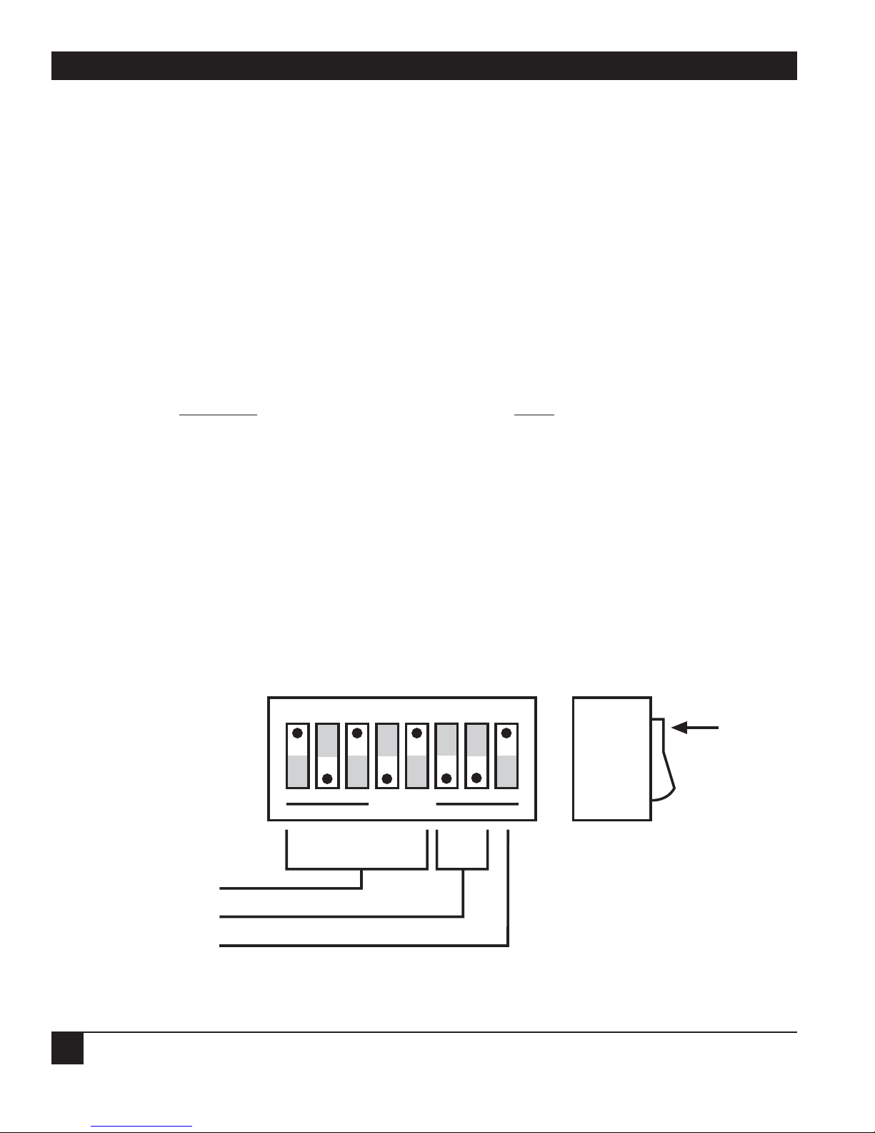
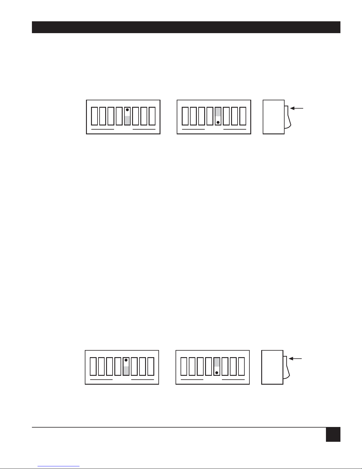
3.1 Configuration
Three internal DIP switches set the interface’s configuration.
NOTE
Selectable functions are read only at power-on and should only be set prior to applying
power to the interface.
The figures below and on the next page illustrate the factory-default conditions, which are:
Serial Por
t: IEEE:
9600 Baud Mode = System Controller
8 Data Bits Address = 10
2 Stop Bits Bus Terminator = CR-LF; EOI Disabled
No Parity Talk-Back Enabled
Serial Terminator = CR-LF
Echo Disabled
RTS/CTS Handshake
Figure 3-1. SW3 factory-default settings.
1 2 3 4 5
6
7 8
OPEN
SW3
IEEE Addr
IEEE Term
EOI
10
CR-LF
Disabled
Switch
Side
View
DOT
3. Getting Started
Page 15

13
CHAPTER 3: Getting Started
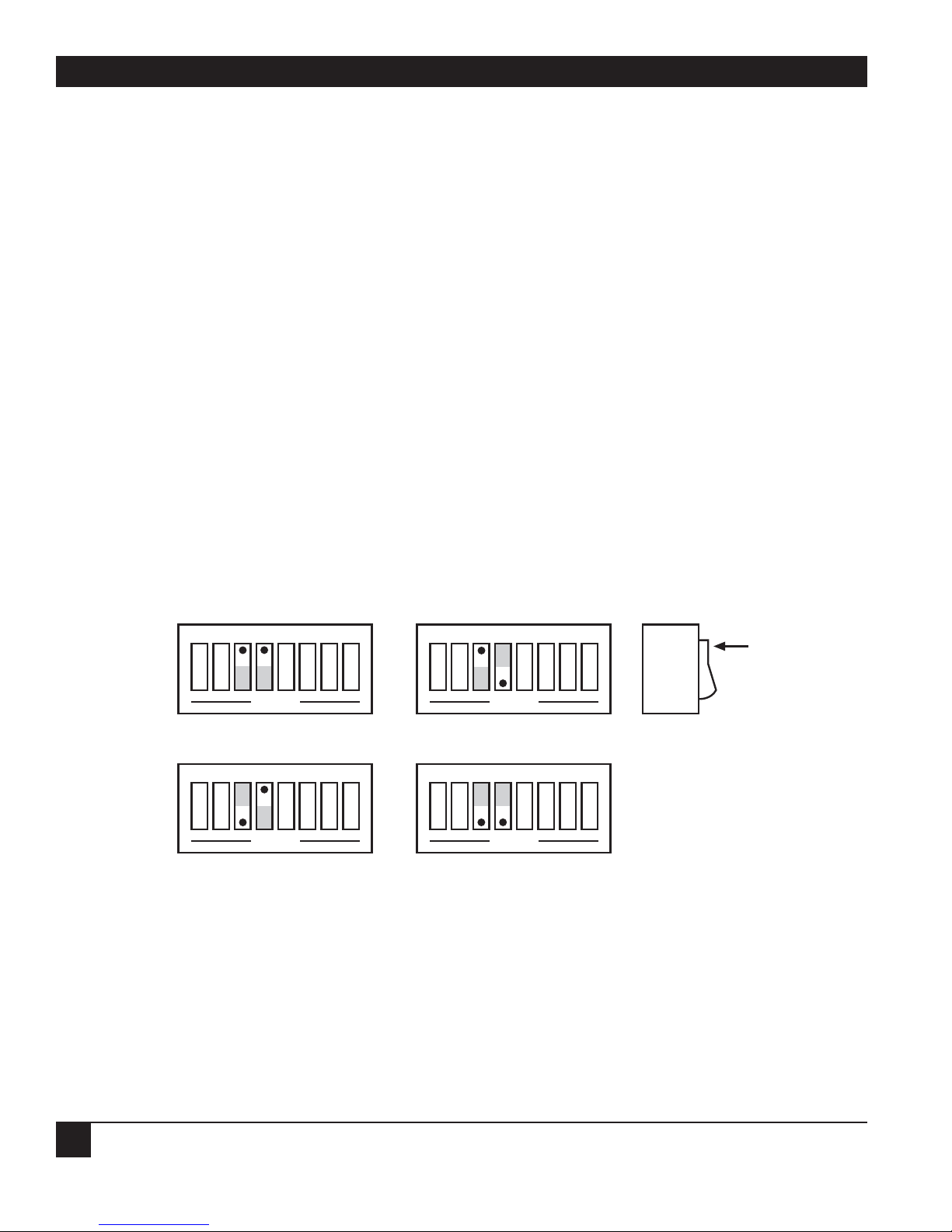
Figure 3-2. SW2 factory-default settings.
Figure 3-3. SW1 factory-default settings.
1 2 3 4 5 6 7 8
OPEN
SW1
Baud Rate
Handshake
Word Length
9600
RTS/CTS
8 Data Bits
Switch
Side
View
DOT
Pass-Thru Feature
Enabled
Stop Bits
2 Stop Bits
1 2 3 4 5 6 7 8
OPEN
SW2
Mode
Serial Term
Echo
SC
CR-LF
Switch
Side
View
DOT
Parity
No Echo
No Parity
Page 16

488 CONTROLLER
14
The 488 Controller is configured as an IEEE controller. In this mode, the 488 Controller allows an RS-232
host computer to control up to 14 IEEE 488 devices. This mode of operation is described in detail, along
with its command descriptions, in Chapters 4 and 5. These sections also cover the Peripheral mode of
operation.
The 488 Controller can be configured to transparently communicate with a single IEEE peripheral, such
as a plotter. This Controller Pass-Thru mode is described in detail in Chapter 6.
The 488 Controller may also be configured as a transparent IEEE Pass-Thru Peripheral. As a Pass-Thru
Peripheral, it allows an IEEE controller to communicate with an RS-232 device. The Peripheral Pass-Thru
operation mode is described in detail in Chapter 7.
To modify any of these defaults, follow this simple procedure:
1) Disconnect the power supply from the AC line and from the 488 Controller. Also disconnect any IEEE
or serial cables prior to disassembly.
WARNING
Never open the 488 Controller’s case while it is connected to the AC line. Failure to
observe this warning may result in equipment failure, personal injury, or death.
2) Place the 488 Controller upside down on a flat surface. Remove the four screws located near the rubber
feet.
3) Return the interface to the upright position and carefully remove the top cover.
4) Change whichever DIP-switch settings you need to change.
5) When you have made all of your changes, reverse this procedure to reassemble the 488 Controller.
3.2 Serial-Port Settings
The first parameters to configure are those that correspond to the RS-232 port. These include baud rate,
word length, number of stop bits, parity selection, and type of RS-232 handshake. Each of these is described
in Sections 3.2.1 through 3.2.6.
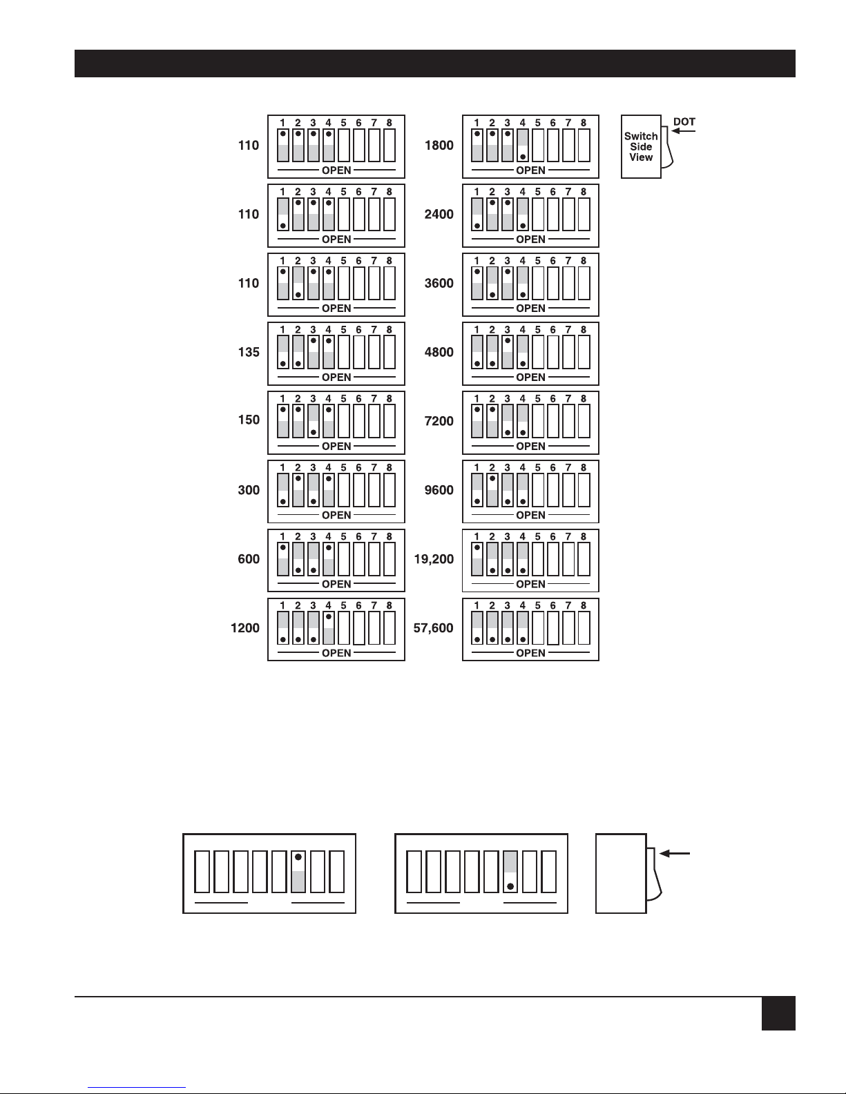
3.2.1 S
ERIAL
BAUD RATE
The “baud rate” is the number of serial bits per second transferred into and out of the serial interface.
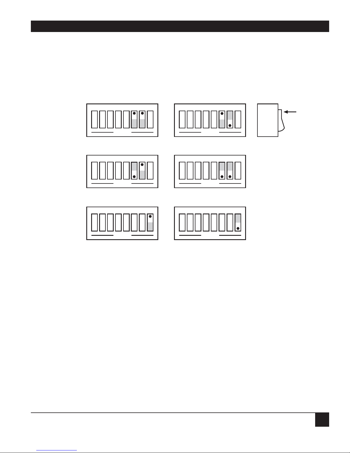
SW1-1 through SW1-4 determine the serial baud rate. The factory-default baud rate is 9600 baud. Baud rates
may be selected from 110 to 57,600 baud. Refer to the following diagram for specific baud rates.
Page 17
15
CHAPTER 3: Getting Started
Figure 3-4. Switch SW1: Selecting the serial baud rate.
3.2.2 SERIAL WORD LENGTH (DATA BITS)
SW1-6 determines the number of data bits, often referred to as word length, for each serial character
transmitted or received. The factory default is 8 data bits.
Figure 3-5. Switch SW1: Selecting the serial word length (data bits).
1 2 3 4 5
6
7 8
OPEN
8 Data Bits
1 2 3 4 5
6
7 8
OPEN
7 Data Bits
Switch
Side
View
DOT
Page 18
488 CONTROLLER
16
3.2.3 SERIAL S
TOP BITS
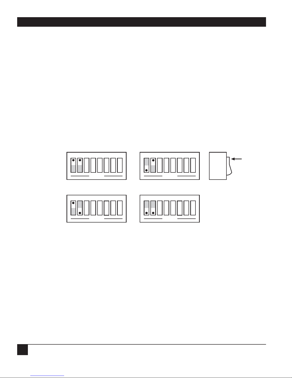
Switch SW1-8 determines the number of stop bits contained in each serial character transmitted
and received. The factory default is 2 stop bits.
Figure 3-6. Switch SW1: Selecting the serial stop bits.
3.2.4 S
ERIAL P
ARITY
Serial parity is selected with S2-6 through S2-8. The 488 Controller generates the selected parity during serial
transmissions but it does not check parity on data that is received. The factory default is parity disabled.
Figure 3-7. Switch SW2: Selecting the serial parity.
Switch
Side
View
DOT
1 2 3 4 567 8
OPEN
Mark Parity
1 2 3 4 567 8
OPEN
Odd Parity
1 2 3 4 567 8
OPEN
Space Parity
1 2 3 4 567 8
OPEN
Even Parity
1 2 3 4 567 8
OPEN
Parity Disabled
Switch
Side
View
DOT
1 2 3 4 5
6
7 8
OPEN
2 Stop Bits
1 2 3 4 5
6
7 8
OPEN
1 Stop Bit
Page 19
17
CHAPTER 3: Getting Started
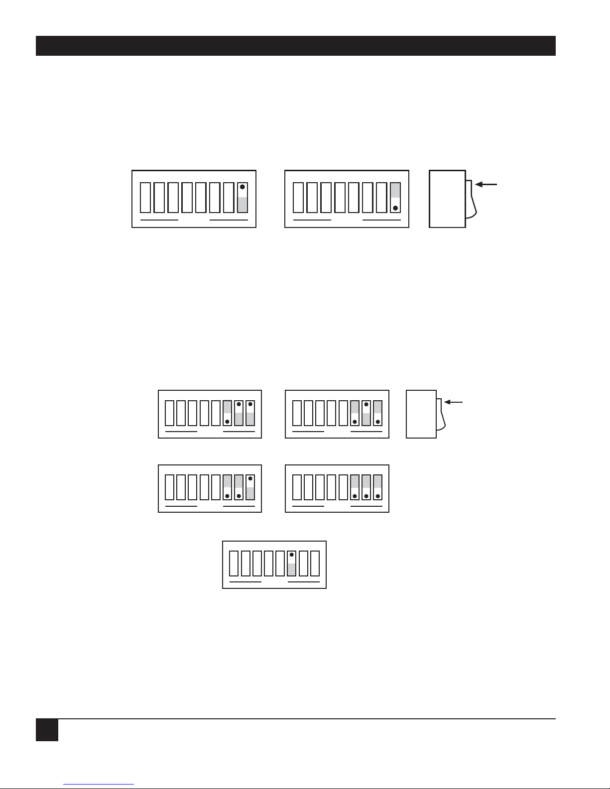
3.2.5 SERIAL E
CHO
Serial data sent to the 488 Controller will be echoed back to the serial host if SW2-5 is set to the open
position. The factory default is Echo Disabled.
Figure 3-8. Switch SW2: Enabling or disabling echo.
3.2.6 S
ERIAL HANDSHAKE
Switch SW1-5 is used to select hardware (RTS/CTS) or software (X-ON/X-OFF) serial handshake control.
With X-ON/X-OFF, the 488 Controller issues an X-OFF character (ASCII value of &H13) when its buffer
memory is near full. When the X-OFF character is sent, there are still more than 1000 character locations
remaining to protect against buffer overrun. When it is able to accept more information, the 488 Controller
issues an X-ON character (ASCII value of &H11). The 488 Controller also accepts X-ON/X-OFF on transmit
from the serial host it is communicating with. RTS/CTS serial control becomes inactive when X-ON/X-OFF
is enabled. The RTS output is, however, set to an active high state. The CTS input is not used for this
handshake and may be left floating (unconnected).
With RTS/CTS, the 488 Controller unasserts RTS (sets RTS low) when its buffer memory is near full. When
RTS is unasserted, there are still more than 1000 character locations remaining to protect against buffer
overrun. When it is able to accept more information, the 488 Controller asserts RTS (sets RTS high). The
488 Controller will not transmit data to the serial host if it detects the CTS input unasserted (low) when
configured for this hardware handshake.
The factory-default serial control is hardware, RTS/CTS.
Figure 3-9. Switch SW1: Selecting the serial handshake.
Switch
Side
View
DOT
1 2 3 4 5
6
7 8
OPEN
RTS/CTS
1 2 3 4 5
6
7 8
OPEN
X-ON/X-OFF
1 2 3 4 5
6
7 8
OPEN
Echo Disabled
1 2 3 4 5
6
7 8
OPEN
Echo Enabled
Switch
Side
View
DOT
Page 20
488 CONTROLLER
18
3.3 Selecting Terminator Substitution
In the Controller and Peripheral Modes, the 488 Controller is not sensitive as to whether CR or LF is used
as a serial input terminator to a command. In general, it requires only one of either to cause command
execution. The IEEE input terminator is fixed to LF. The switches that allow terminator selection, shown in
the following diagrams, set only the serial output and IEEE output terminators for these operation modes.
In the transparent Pass-Thru modes, the 488 Controller can be configured to provide RS-232-to-IEEE 488
and IEEE-488-to-RS-232 terminator substitution. This is useful when interfacing an RS-232 device which only
issues carriage return (CR) as an output terminator to an IEEE controller which expects a carriage return
followed by a line feed (CR-LF).
In the above case, the serial terminator should be selected for CR Only while the IEEE terminator is set to
CR-LF. When a serial CR character is received, it is discarded, and an IEEE CR-LF is substituted for it. In the
IEEE-to-RS-232 direction, the IEEE CR is unconditionally discarded. When it receives the IEEE LF, a serial
CR is substituted.
To make the 488 Controller totally data transparent in the Pass-Thru modes, set both the serial and IEEE
terminators to be CR Only or LF Only.
3.3.1 S
ERIAL TERMINATOR
SW2-3 and SW2-4 select the serial terminators for the serial input (Pass-Thru Modes Only) and output.
The factory default is CR-LF.
Figure 3-10. Switch SW2: Selecting the serial terminator.
Switch
Side
View
DOT
CR Only
1 2 3 4 5
6
7 8
OPEN
LF-CR
1 2 3 4 5
6
7 8
OPEN
1 2 3 4 5
6
7 8
OPEN
LF Only
1 2 3 4 5
6
7 8
OPEN
CR-LF
Page 21
19
CHAPTER 3: Getting Started
3.3.2 IEEE BUS T
ERMINATOR
SW3-6 through SW3-8 set the IEEE bus terminators used for data sent or received (Pass-Thru modes only)
by the 488 Controller. EOI, a line used to signal the end of a multiple character bus transfer, may also be
enabled. If enabled, EOI is asserted when the last selected bus terminator is sent. Factory default is CR-LF
with EOI disabled.
Figure 3-11. Switch SW3: Selecting the IEEE bus terminator.
3.4 Selecting the Mode
SW2-1 and SW2-2 set the major operating mode of the 488 Controller. There are four distinct modes
of operation.
1. System Controller
2. Peripheral
3. Controller Pass-Thru
4. Peripheral Pass-Thru
Switch
Side
View
DOT
1 2 3 4 5
6
7 8
OPEN
LF Only
1 2 3 4 5
6
7 8
OPEN
CR-LF
1 2 3 4 5
6
7 8
OPEN
CR Only
1 2 3 4 5
6
7 8
OPEN
LF-CR
1 2 3 4 5
6
7 8
OPEN
EOI Disabled
1 2 3 4 5
6
7 8
OPEN
EOI Enabled
Page 22
488 CONTROLLER
20
As a System Controller, the 488 Controller accepts simple high-level ASCII commands from a serial host. It
interprets these commands and performs the required bus action to bidirectionally communicate with up to
14 IEEE devices. As a Peripheral, the 488 Controller becomes a bus device. It accepts simple high-level ASCII
commands from a serial host and interprets these commands and status to communicate with another IEEE
controller. Applications include computer-controlled automatic test systems. These operation modes are
discussed in Chapters 4 and 5.
The IEEE Controller Pass-Thru (RS-232 to IEEE Converter) mode allows a serial host device to send data to
a single IEEE bus peripheral. Applications include interfacing a listen-only or addressable IEEE
printer/plotter to a serial printer port. Refer to Chapter 6 for more detailed information on the Controller
Pass-Thru operation mode.
The Peripheral Pass-Thru mode is used when interfacing a serial device to an IEEE controller. Data which
is sent by the IEEE controller to the 488 Controller is transmitted out its serial port. Data received from the
serial device is buffered by the 488 Controller until it is read by the IEEE controller. Refer to Chapter 7 for
more detailed information on the Peripheral Pass-Thru operation mode.
The factory default is the System Controller mode.
Figure 3-12. Switch SW2: Selecting the mode.
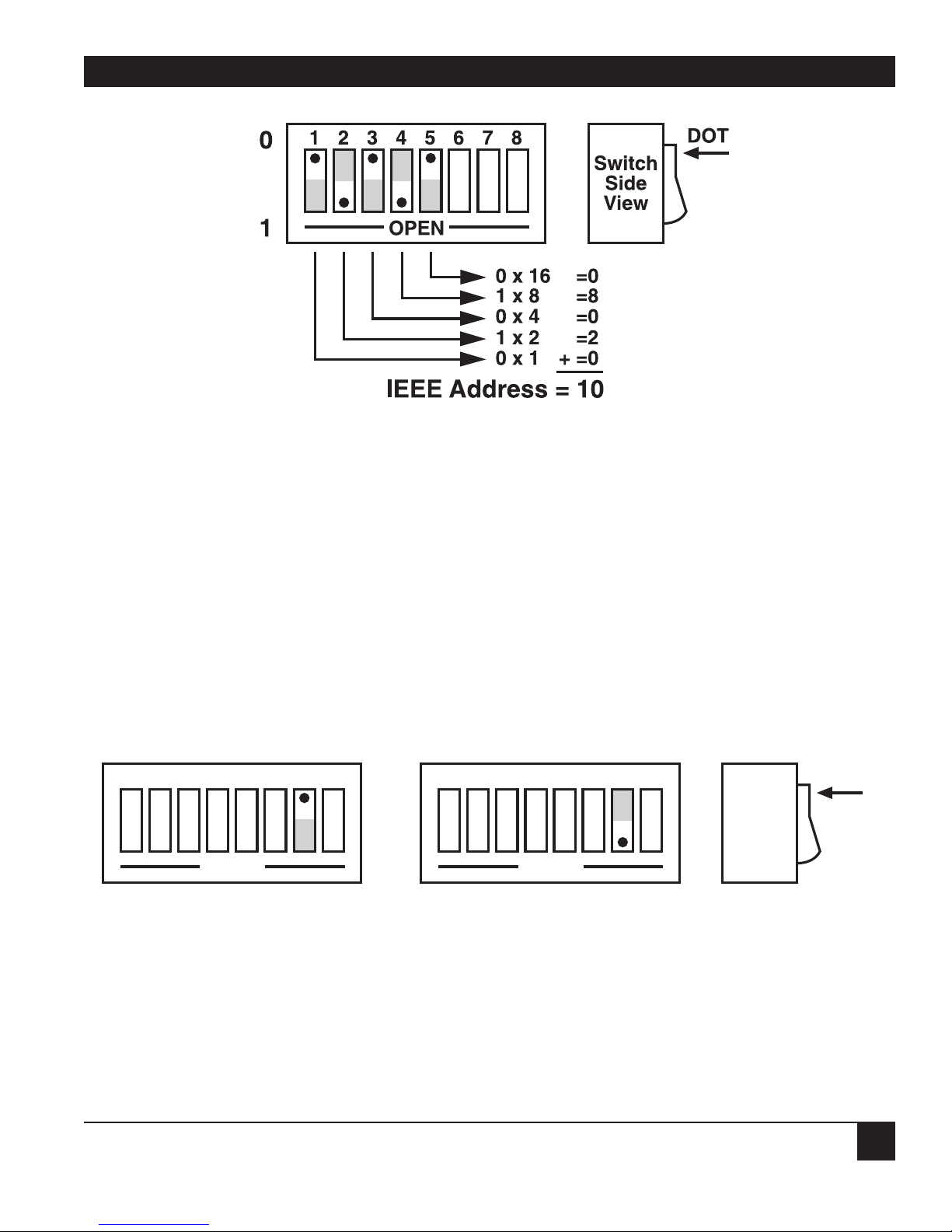
3.5 Selecting the IEEE Address
SW3-1 through SW3-5 select the IEEE bus address of the 488 Controller when in the System Controller,
Peripheral and Peripheral Pass-Thru modes. These same switches are used in the Controller Pass-Thru mode
to select the address of the device that will be controlled. (Refer to Chapter 7 for additional information.)
The address is selected by simple binary weighting, with SW3-1 being the least significant bit and SW3-5 the
most significant. The factory default is address 10.
Listen Only is a special type of Peripheral Pass-Thru operation. In the Listen Only mode the 488 Controller
accepts all data transmitted on the bus, ignoring any bus addressing, and transfers it out its serial port. The
488 Controller is set to Listen Only mode by setting its address to 31. If the IEEE address is set to 31 in the
System Controller, Peripheral, or Peripheral Pass-Thru mode, it is adjusted to address 30.
Switch
Side
View
DOT
1 2 3 4 5
6
7 8
OPEN
Controller Pass-Thru
1 2 3 4 5
6
7 8
OPEN
Peripheral Pass-Thru
1 2 3 4 5
6
7 8
OPEN
Peripheral
System Controller
1 2 3 4 5
6
7 8
OPEN
Page 23
21
CHAPTER 3: Getting Started
Figure 3-13. Switch SW3: Selecting the IEEE address.
3.6 Feature Selections
The functions of the remaining switches are dependent on the mode selected. A brief description of each
of these features follows. Refer to the listed sections for additional information.
3.6.1 CONTROLLER PASS-THRU FEATURES
In the IEEE Controller (RS-232-to-IEEE-488 converter) mode, SW1-7 determines whether the interface
should, after sending the IEEE bus terminators, address the attached bus device to talk. The factory default
is Talk-back On Terminator enabled.
Refer to Chapter 6 for complete details on these features.
Figure 3-14. Switch SW1: Enabling or disabling “Talk Back on Terminator” in Controller mode.
Switch
Side
View
DOT
1 2 3 4 5
6
7 8
OPEN
Talk-Back on
Terminator Disabled
1 2 3 4 5
6
7 8
OPEN
Talk-Back on
Terminator Enabled
Page 24
488 CONTROLLER
22
3.6.2 PERIPHERAL P
ASS-THRU FEATURES
In the Peripheral Pass-Thru (IEEE-488-to-RS-232 converter) mode, SW1-7 enables the interface to assert
the SRQ IEEE bus interface line to indicate that it has received the last-switch-selected serial terminator
character from the serial device.
Figure 3-15. Switch SW1: Enabling or disabling SRQ on last serial terminator in Peripheral mode.
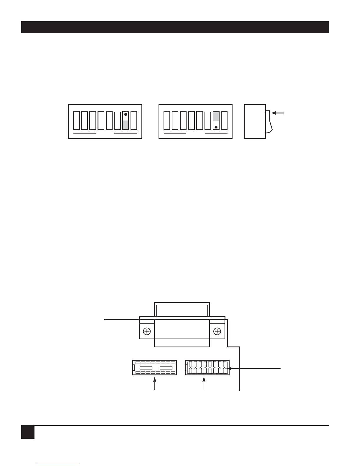
3.7 Serial Interface
The 488 Controller has the ability to output signal levels that are compatible with either RS-232 or RS-422.
An internal DIP shorting plug determines which electrical specification is chosen. If the interface is to be
connected to an IBM
®
PC or compatible, select the RS-232 level. If it will be connected to a Macintosh®, use
the RS-422 level. For connection to other computers, refer to the manufacturer’s manual to determine
which levels are supported.
3.7.1 RS-232/RS-422 S
IGNAL LEVEL SELECTION
The 488 Controller’s factory default signal levels are compatible with RS-232. To select RS-422 levels,
carefully remove the 8-position shorting plug with a small flat-blade screwdriver from J106. Install the
DIP jumper into J205, making certain that all shorting plug pins are inserted correctly.
Figure 3-16. Selecting RS-232 or RS-422 signal levels.
Switch
Side
View
DOT
1 2 3 4 5
6
7 8
OPEN
SRQ on Last
Terminator Disabled
1 2 3 4 5
6
7 8
OPEN
SRQ on Last
Terminator Enabled
Shorting Plug
RS-232
RS-422
Page 25
23
CHAPTER 3: Getting Started
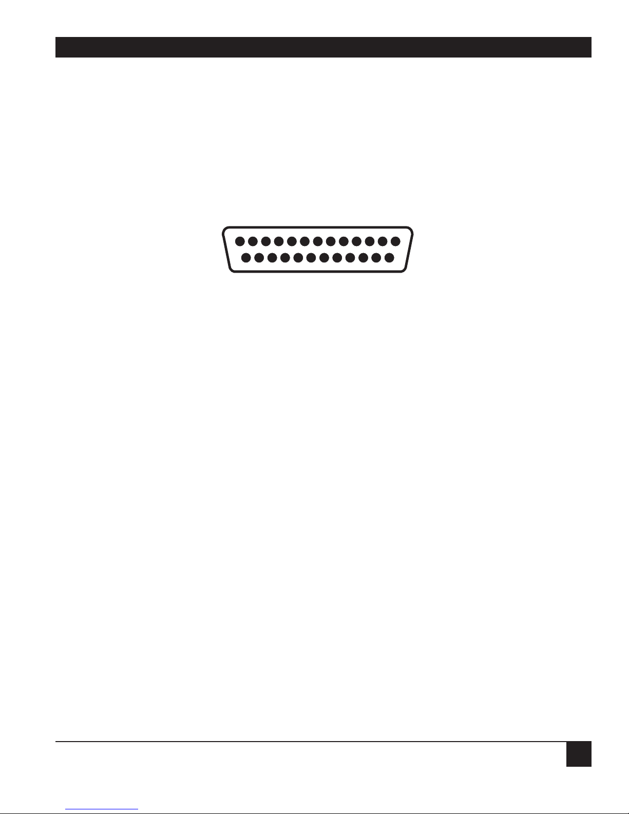
3.7.2 SERIAL S
IGNAL DESCRIPTIONS
The 488 Controller is equipped with a standard DB25 female connector on its rear panel and requires
a standard DB25 male mating connector. The 488 Controller’s connector is configured as DCE type
equipment for RS-232 communications, which means the 488 Controller always transmits data on Pin 3
and receives data on Pin 2. The following lists and describes the RS-232 and RS-422 signals provided on
the 488 Controller.
Figure 3-17. Rear view of the 488 Controller’s serial connector.
-RxD Receive Data—Input—Pin 2
This pin accepts serial data sent by the RS-232 or RS-422 host. The serial data is expected
with the word length, baud rate, stop bits, and parity selected by the internal switches. The
signal level is low true.
-TxD Transmit Data—Output—Pin 3
This pin transmits serial data to the RS-232 or RS-422 host. The serial data is sent with the
word length, baud rate, stop bits, and parity selected by the internal switches. The signal
level is low true.
CTS Clear To Send—Input—Pin 4
The CTS input is used as a hardware-handshake line to prevent the 488 Controller from
transmitting serial data when the RS-232 host is not ready to accept it. When RTS/CTS
handshake is selected on the internal switches, the 488 Controller will not transmit data
out -TxD while this line is unasserted (lowered). If the RS-232 host is not capable of driving
this line it can be connected to the Vtest output (Pin 6) of the 488 Controller. If X-ON/X-OFF
handshake is selected, the CTS line is not tested to determine if it can transmit data.
RTS Request To Send—Output—Pin 5
The RTS output is used as a hardware handshake line to prevent the RS-232/RS-422 host
from transmitting serial data if the 488 Controller is not ready to accept it. When RTS/CTS
handshake is selected on the internal switches, the 488 Controller will drive the RTS output
high when there are more than 1000 character locations available in its internal buffer. If
the number of available locations drops to less than 1000, the 488 Controller will unassert
(lower) this output. If X-ON/X-OFF handshake is selected, the RTS line will be permanently
driven active high.
13 1
25 14
-RXD
-TXD
CTS
RTS
+VTEST
GND
+VTEST
+RXD
+TXD
Page 26
488 CONTROLLER
24
+Vtest Test Voltage—Output—Pin 6
This pin is connected to +5 volts through a 1K resistor. It is also common to Vtest on pin 9.
Gnd Ground—Pin 7
This pin sets the ground reference point for the other RS-232 inputs and outputs.
+Vtest Test Voltage—Output—Pin 9
This pin is connected to 5 volts through a 1K resistor. It is also common to Vtest on pin 6.
+RxD Receive Data Plus—Input—Pin 14
This pin accepts serial data sent by the RS-422 host. The serial data is expected with the word
length, baud rate, stop bits, and parity selected by the internal switches. The signal level is
high true and only connected to this pin when RS-422 operation is selected. It is 180 degrees
out of phase with -RxD.
+TxD Transmit Data Plus—Output—Pin 16
This pin transmits serial data to the RS-422 host. The serial data is sent with the word length,
baud rate, stop bits, and parity selected by the internal switches. The signal level is high true
and only connected to this pin when RS-422 operation is selected. It is 180 degrees out of
phase with -TxD.
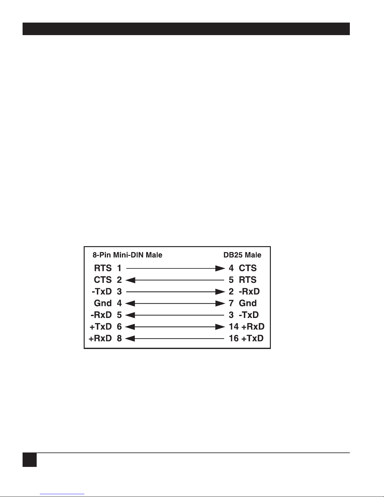
3.7.3 S
ERIAL-CABLE WIRING DIAGRAMS
If a cable was not purchased with the 488 Controller, the following diagrams will help you make your own
cable. Simple soldering skills and attention to detail will ensure successful construction.
Figure 3-18. Wiring diagram: Macintosh to 488 Controller.
Page 27
25
CHAPTER 3: Getting Started
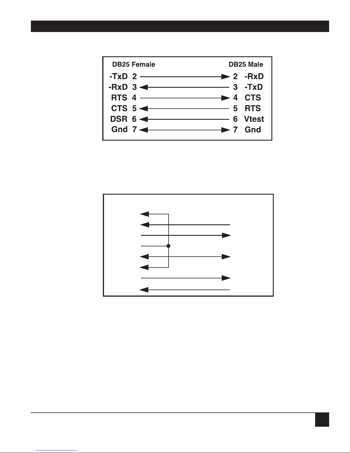
Figure 3-19. Wiring diagram: IBM PC or compatible with DB25
serial connector to 488 Controller (RS-232).
Figure 3-20. Wiring diagram: IBM AT
®
or compatible with DB9
serial connector to 488 Controller (RS-232).
NOTE
Standard AT 9-pin-to-25-pin adapter cables are not wired as shown above and will not work
with the 488 Controller.
DCD 1
-RxD 2 3 -TxD
-TxD 3 2 -RxD
DTR 4
Gnd 5 7 Gnd
DSR 6
RTS 7 4 CTS
DB9 Female DB25 Male
CTS 8 5 RTS
Page 28

488 CONTROLLER
26
3.8 General Operation
Refer to the following sections for specific operational modes. This section gives a general test of functionality. After setting the power-on defaults and reassembling the 488 Controller, plug the power-supply
connector into the rear jack on the interface.
CAUTION
Never plug the power supply into the 488 Controller while it is connected to AC line power.
If you do, you could damage the 488 Controller.
WARNING
The power supply provided with the interface is intended for indoor use only. Using it
outdoors could result in equipment failure, personal injury, or death.
After plugging the power supply connector into the 488 Controller, plug the power supply into AC line
power. Turn the rear-panel power switch ON (the “1” position). All the front-panel indicators should light
momentarily while the 488 Controller performs an internal ROM and RAM self-check. At the end of this
self-check, all indicators except POWER should turn off.
If there is an error in the ROM checksum, all of the LEDs will remain on. Flashing LEDs indicate a RAM
failure. Should such an error occur, turn the rear-panel switch to the OFF (0) position and retry the above
procedure.
If the front-panel indicators do not flash and the POWER indicator does not remain lit, there may not be
any power supplied to the interface. If this happens, check the AC line and the power supply’s rear-panel
connection.
If the controller operates properly, connect an interface cable to the 488 Controller’s rear (DB25)
connector. Connect the other end to the host’s serial port. Except for connecting IEEE bus instruments, the
488 Controller is installed and ready to use.
WARNING
The 488 Controller makes its earth ground connection through the serial interface cable. It
should only be connected to IEEE bus devices after being first connected to the host.
Failure to do so may allow the 488 Controller to float to a bus device test voltage. This
could result in damage to the 488 Controller, personal injury, or death.
Page 29

27
CHAPTER 3: Getting Started
3.9 Is Anyone Out There?
Before connecting any IEEE bus devices to the 488 Controller, try this simple operational check. The 488
Controller must be configured for either System Controller or Peripheral mode operation. This test will
not work in either of the Pass-Thru modes.
Running BASIC on the host, or any programming language which supports the serial ports, type the
following (or its equivalent).
OPEN "COM1:9600, N, 8, 2, cd, ds" AS 1 [Return]
PRINT #1,"HELLO" [Return]
LINE INPUT #1,A$ [Return]
PRINT A$ [Return]
The 488 Controller will respond with (and the host will display):
488 Controller Revision N.N Copyright (C) 1988
where N.N is the release and revision number of the firmware.
If you obtain the response above, then your 488 Controller is fine and ready to connect your host to the
powerful IEEE-488 General Purpose Interface Bus. If you did not receive the message above, check that the
interface cable is properly connected and fits. If the 488 Controller is not installed correctly, call Black Box
Technical Support.
Page 30

488 CONTROLLER
28
4.1 Introduction
There are four types of IEEE bus devices: Active Controllers, Peripherals, Talk-Only devices, and ListenAlways devices. Talk-Only and Listen-Always devices are usually used together, in simple systems, such as
a Talk-Only digitizer sending results to a Listen-Always plotter. In these simple systems, no controller is
needed, because the talker assumes that it is the only talker on the bus, and the listener(s) assume that
they are all supposed to receive all the data sent over the bus. This is a simple and effective method of
transferring data from one device to another, but is not adequate for more complex systems where, for
example, one computer is controlling many different bus devices.
In more complex systems, the Active Controller sends commands to the various bus Peripherals telling them
what to do. Commands such as Unlisten, Listen Address Group, Untalk, and Talk Address Group are sent by
the controller to specify which device is to send data, and which devices are to receive it. For more details
about the IEEE bus protocols, see Chapter 8.
When an IEEE bus system is first turned on, some device must be the Active Controller. This device is the
System Controller and always keeps some control of the bus. In particular, the System Controller controls
the Interface Clear (IFC) and Remote Enable (REN) bus management lines. By asserting Interface Clear,
the System Controller forces all the other bus devices to stop their bus operations, and regains control as
the Active Controller.
4.2 Operating Mode Transitions
The System Controller is initially the Active Controller. It can, if desired, pass control to another device
and thereby make that device the Active Controller. The System Controller remains the System Controller.
The device to which control is passed must be able to take on the Active Controller role. It would make no
sense to try to pass control to a printer. Control should only be passed to other computers that are capable,
and ready, to become the Active Controller. There must be exactly one System Controller on the IEEE bus.
All other potential controllers must be configured as Peripherals when they power on.
The state diagram on the next page shows the relationships between the various operating modes. The top
half of the state diagram shows the System Controller’s two operating states. At power-on, it is the active
controller. It directs the bus transfers by sending the bus commands mentioned previously. It also has
control of the Interface Clear and Remote Enable bus lines. The System Controller can pulse Interface
Clear to reset all other bus devices.
As shown in the diagram, the System Controller can pass control to some other bus device and thereby
become a Peripheral to the new Active Controller. If the System Controller receives control from the new
Active Controller, then it will once again become the Active Controller. The System Controller can also
force the Active Controller to relinquish control by asserting the Interface Clear signal.
The bottom half of the state diagram shows the two operating states of a Not System Controller device. At
power on, it is a Peripheral to the System Controller, which is the Active Controller. If it receives control
from the Active Controller, it becomes the new Active Controller. Even though it is the Active Controller, it
is still not the System Controller. The System Controller can force the Active Controller to give up control
by asserting Interface Clear. The Active Controller can also give up control by passing control to another
device, which may or may not be the System Controller.
4. IEEE Operating Modes
Page 31

29
CHAPTER 4: IEEE Operating Modes
Figure 4-1. IEEE bus operating modes state diagram.
In summary, a bus device is set in hardware as either the sole System Controller in the system, or as a nonSystem Controller. At power on, the System Controller is the Active Controller, and the other devices are
Peripherals. The System Controller can give up control by Passing Control, and can regain control by
asserting Interface Clear, or by receiving control. A Peripheral can become the Active Controller by
receiving control, and can give up control by Passing Control, or upon detecting Interface Clear.
Active
System
Controller
SC-CA
Active
Controller,
Not System
Controller
*SC-CA
System
Controller,
Not Active
SC-*CA
Peripheral,
Not System
Controller
*SC-*CA
Power On
Power On
Controller Active (CA) Peripheral (*CA)
Not System Controller (*SC)
Passes Control
Receives Control or
Asserts Interface Clear
Receives Control
Passes Control or
Detects Interface Clear
System Controller (SC)
Page 32

488 CONTROLLER
30
4.3 System Controller Mode
The most common 488 Controller configuration is as the System Controller, controlling several IEEE-bus
instruments. In this mode, the 488 Controller can perform all of the various IEEE-bus protocols necessary to
control and communicate with any IEEE-488-bus devices. As the System Controller in the Active Controller
mode, the 488 Controller can use all commands that are available for the Active Controller state, plus
control the Interface Clear and Remote Enable lines. The allowed bus commands and their actions are as
follows:
ABORT Pulse Interface Clear.
LOCAL Unassert Remote Enable, or send Go To Local to selected devices.
REMOTE Assert Remote Enable, optionally setting devices to Remote.
LOCAL LOCKOUT Prevent local (front-panel) control of bus devices.
CLEAR Clear all or selected devices.
TRIGGER Trigger selected devices.
ENTER Receive data from a bus device.
OUTPUT Send data to bus devices.
PASS CONTROL Give up control to another device which becomes the Active
Controller.
SPOLL Serial Poll a bus device, or check the Service Request state.
PPOLL Parallel Poll the bus.
PPOLL CONFIG Configure Parallel Poll responses.
PPOLL DISABLE Disable selected bus devices’ Parallel Poll response.
PPOLL UNCONFIG Disable all bus devices’ Parallel Poll response.
SEND Send low-level bus sequences.
RESUME Unassert Attention. Used to allow Peripheral-to-Peripheral transfers.
Page 33

31
CHAPTER 4: IEEE Operating Modes
4.4 System Controller, Not Active Controller Mode
After Passing Control to another device, the System Controller is no longer the Active Controller. It acts
as a Peripheral to the new Active Controller, and the allowed bus commands and their actions are modified
accordingly. However, it still maintains control of the Interface Clear and Remote Enable lines. The available
bus commands and their actions are:
ABORT Pulse Interface Clear.
LOCAL Unassert Remote Enable.
REMOTE Assert Remote Enable.
ENTER Receive data from a bus device as directed by the Active Controller.
OUTPUT Send data to bus devices as directed by the Active Controller.
REQUEST Set own Serial Poll request (including Service Request) status.
SPOLL Get own Serial Poll request status.
As a bus Peripheral, the 488 Controller must respond to the commands issued by the Active Controller. The
controller can, for example, address the 488 Controller to listen in preparation for sending data. There are
two ways to detect our being addressed to listen: through the STATUS command, or by detecting an event
with the ARM or ON DOMACRO commands.
The STATUS 1 command can be used to watch for commands from the Active Controller. The Operating
Mode, which is a “P” while the 488 Controller is a Peripheral, will change to a “C” if the Active Controller
Passes Control to the 488 Controller. The Addressed State will go from Idle (I) to Listener (L) or Talker (T)
if the 488 Controller is addressed to listen or to talk, and will go back to Idle (I) when the Active Controller
issues Unlisten (UNL), Untalk (UNT), or specifies another talker (TAG). The Triggered (T1) and Cleared
(C1) indicators will be set when the 488 Controller is triggered or cleared, and reset when STATUS 1 is read.
The Address Change indicator will be set (G1) when the address state changes. These indicators allow the
program to sense the commands issued to the 488 Controller by the Active Controller. The following BASIC
program fragment illustrates how to use the Address Change and Addressed State indicators to
communicate with the Active Controller.
Page 34

488 CONTROLLER
32
First, we check STATUS until it indicates that there has been an address change:
200 PRINT#1,"STATUS1"
210 INPUT#2 ST$
220 'Has there been no Address Change?
230 IF MID$(ST$,7,1)="0" THEN 200
240 'Are we still in the idle state?*
250 STATE$=MID$(ST$,9,1)
260 IF STATE$="I" THEN 200
270 'Are we addressed to listen?
280 IF STATE$="L" THEN 400
290 'Are we addressed to talk?
300 IF STATE$="T" THEN 500
310 PRINT "BAD ADDRESSED STATE VALUE: ";ST$: STOP
*This means “are we still in a state where there is no communication.”
If we are addressed to listen, then we ENTER a line from the controller and print it out.
400 'Listen state
410 PRINT#1,"ENTER"
420 LINE INPUT#1,A$
430 PRINT A$
440 GOTO 200
If we are addressed to talk, then we INPUT a line from the keyboard and OUTPUT it to the controller.
500 'Talk state
510 LINE INPUT A$
520 PRINT#1,"OUTPUT;";A$
530 GOTO 200
Page 35

33
CHAPTER 4: IEEE Operating Modes
You can also detect these conditions with the ARM or ON DOMACRO commands and handle them in an
exception as described in Chapter 5. The various arm conditions and their meanings are as follows:
SRQ The internal Service Request state is set. See the SPOLL command in
Chapter 5.
PERIPHERAL The 488 Controller is in the Peripheral (*CA) operating mode.
CONTROLLER The 488 Controller is the Active Controller (CA).
TRIGGER The 488 Controller, as a Peripheral, has received a Trigger bus command.
CLEAR The 488 Controller, as a Peripheral, has received a Clear bus command.
TALK The 488 Controller is in the Talk state and can OUTPUT to the bus.
LISTEN The 488 Controller is in the Listen state and can ENTER from the bus.
IDLE The 488 Controller is in neither the Talk nor Listen state.
CHANGE An Address Change has occurred, i.e. a change between Peripheral and
Controller, or among Talk, Listen, and Idle has occurred.
ERROR An error, either command or bus, has been detected by the 488 Controller.
4.5 Not System Controller Mode
If the 488 Controller is configured as not the System Controller then, at power on, it will be a bus
Peripheral. It might use a program like the one described previously to communicate with the Active
Controller. The bus commands available to the 488 Controller when it is not the System Controller and
not the Active Controller (*SC*CA) are:
ENTER Receive data from a bus device as directed by the Active Controller.
OUTPUT Send data to bus devices as directed by the Active Controller.
REQUEST Set own Serial Poll request (including Service Request) status.
SPOLL Get own Serial Poll request status.
Page 36

488 CONTROLLER
34
4.6 Active Controller, Not System Controller Mode
If the Active Controller passes control to the the 488 Controller, then the 488 Controller will become the
new Active Controller. This can be detected by the STATUS command or as an ARMed event. As an Active
Controller, but not the System Controller, the following bus commands are available:
ABORT Assert Attention and send My Talk Address to stop any bus transfers.
LOCAL Send Go To Local to selected devices.
LOCAL LOCKOUT Prevent local (front-panel) control of bus devices.
CLEAR Clear all or selected devices.
TRIGGER Trigger selected devices.
ENTER Receive data from a bus device.
OUTPUT Send data to bus devices.
PASS CONTROL Give up control to another device, which becomes the Active Controller.
SPOLL Serial Poll a bus device, or check the Service Request state.
PPOLL Parallel Poll the bus.
PPOLL CONFIG Configure Parallel Poll responses.
PPOLL DISABLE Disable the selected bus devices’ Parallel Poll response.
PPOLL UNCONFIG Disable all bus devices’ Parallel Poll response.
SEND Send low-level bus sequences.
RESUME Unassert Attention. Used to allow Peripheral-to-Peripheral transfers.
4.7 Controller Pass-Thru Mode
This mode is intended to provide bidirectional data-transparent conversion between an RS-232/RS-422 host
computer and an IEEE 488 peripheral, such as a printer or an HP
®
-IB plotter. This mode’s operation is
covered in Chapter 6 of this manual.
4.8 Peripheral Pass-Thru Mode
This mode provides bidirectional data transparent conversion between an IEEE 488 controller and a serial
device. This Peripheral Pass-Thru mode does not require the serial device to control data to it. There is no
command line, so this mode requires no serial commands. This operation mode is described in Chapter 7.
Page 37

35
CHAPTER 5: Command Descriptions
5.1 Introduction
This section contains a detailed description of each of the high-level commands available for the 488
Controller. There are two types of commands: bus commands and system commands. Bus commands
communicate with the IEEE 488 bus. System commands configure or request information from the
488 Controller.
Bus Commands:
ABORT PPOLL CONFIG
CLEAR PPOLL DISABLE
ENTER PPOLL UNCONFIG
LOCAL REMOTE
LOCAL LOCKOUT REQUEST
OUTPUT RESUME
PASS CONTROL SEND
PPOLL SPOLL
TRIGGER
System Commands:
ARM MACROENDM
COMMENT MASK
COUNT MEMORY
DELAY ON <event> DOMACRO
DISARM READ
DOMACRO RESET
ERASE STATUS
ERROR STERM
HELLO TERM
ID TIME OUT
TRACE
5. Command Descriptions
Page 38

488 CONTROLLER
36
5.2 Command-Description Format
Each command description is divided into several areas.
5.2.1 S
YNTAX
The command description’s syntax section describes the proper command syntax which must be sent to the
488 Controller using the IBM BASIC PRINT# command, or its equivalent in other languages, to the COM
port. The following conventions are used in the syntax descriptions:
No command, along with its options, may be more than 127 characters long. The OUTPUT command’s data
part is not constrained by this length. It is, however, limited to the available USER MEMORY. The OUTPUT
#count;data may be as long as necessary. Refer to the OUTPUT command for more information.
Enter items in capital letters, such as ENTER or OUTPUT, exactly as stated, except use abbreviations with
some commands to reduce serial transmission traffic.
Items in lower case, such as addr or count, represent parameters which must be substituted with an
appropriate value.
Blank spaces in commands are generally ignored. Thus, LOCAL LOCK OUT is the same as
LOCALLOCKOUT. Spaces are not ignored in four places: the OUTPUT command’s data part, within
quoted strings in a SEND command, after an apostrophe (') in a terminator specification (term), and after
the semicolon following the ID command.
The number sign (#) and the semicolon (;) must be present exactly as shown. A comma (,) represents an
address separator. You can use the slash (/) or period (.) in its place as the address separator.
Use optional semicolons ([;]) if desired.
Items enclosed in square brackets ([item]) are optional. Multiple items enclosed in square brackets
separated by vertical lines ([item1|item2|item3]) are optional; any one or none may be chosen. No more
than one item may be selected.
Ellipses (...) within square brackets mean that the items in the brackets may be repeated as many times as
desired.
Braces, or curly brackets ({item1|item2}), mean that exactly one of the enclosed items is required.
Bracket combinations are possible. For example, {term[term] [EOI] |EOI} allows the choice of “term,” “term
EOI,” “term term,” “term term EOI,” or just “EOI,” but does not allow the choice of “nothing.”
Numeric parameters (those that are given as numbers) are decimal unless preceded by &H, in which case
they are considered to be hexadecimal. Thus 100 is decimal 100, &H64 is hexadecimal 64 which equals
decimal 100, &HFF is decimal 255, and 0FF is invalid because F is not a valid decimal digit. The only
exception to this rule is that bus addresses, both primary and secondary, must be specified as two-digit
decimal numbers. Hexadecimal bus addresses are not allowed.
Several commands require additional or optional parameters. These are further described with each
command, but the more common ones are discussed next.
Page 39

37
CHAPTER 5: Command Descriptions
Bus Addressing
pri-addr A two-digit primary device address in the range of 00 to 30.
sec-addr An optional two-digit secondary device address in the range of 00 to 31.
addr An IEEE bus address. A numeric primary address optionally followed by a secondary
address. Thus addr is of the form...
{pri-addr [sec-addr]}
where pri-addr is a two-digit primary address in the range from 00 through 30 and
sec-addr is a two-digit secondary address from 00 through 31. Numeric addresses
must be given as two-digit numbers: for example, 05 for address 5, and 1601 for
primary address 16, secondary address 1.
[,addr] An optional bus addresses list, each address preceded by an address separator: either
a comma (,), a slash (/) or a period (.).
No more than 15 bus addresses are allowed in any single command.
Character Count
#count The number of characters to be transferred. A pound sign (#) followed by an integer
in the range of 1 to 65535 (2
16
-1). May be specified in hexadecimal by preceding it
with &H. The hexadecimal range is &H1 to &HFFFF. A zero character count is
invalid.
ASCII Characters
$char A single character whose ASCII value is the number char, a decimal number in the
range from 0 to 255, or a hexadecimal number in the range from &H0 to &HFF. For
example, $65 is the letter “A,” as is $&H41.
CR The carriage return character ($13, $&H0D).
LF The line feed character ($10, $&H0A).
'X Any printable character. The apostrophe is immediately followed, without any
intervening spaces, by a single character which is taken to be the character specified.
ASCII Character Strings
data An arbitrary characters string. No special forms given above ($char, CR, LF, or 'X)
are used. For example, CRLF as data is taken as the letters “C,” “R,” “L,” and “F,” not
as carriage return and line feed.
'data' An arbitrary characters string enclosed in apostrophes (') or quotes (").
Page 40

488 CONTROLLER
38
Terminators
term Any single character, specified as CR, LF, 'X, or $char as described previously. Part
of terminator sequence used to mark data and commands’ lines’ ends.
[term] An optional term character. term[term], means that one or two terminators may
be specified.
EOI The IEEE bus End-Or-Identify signal. When asserted during the transfer of a
character, EOI signals that that character is the last in the transfer. On input, EOI,
if specified, causes the input to stop. On output, EOI causes the bus EOI signal to
be asserted during transmission of the last character.
NONE The no-end-of-line-character indicator. When STERM NONE is specified, the 488
Controller does not append any serial output terminator(s) to serially transmitted
data.
5.2.2 R
ESPONSE
The command description’s response section describes the response that the user’s program should read
from the serial host’s COM port after sending the command. If a response is provided, it must be read to
maintain proper program sequence.
5.2.3 MODE
This command description section specifies the operating modes in which the command is valid.
The 488 Controller may be configured as the System Controller, in which case it will initially be the Active
Controller, or as a Not System Controller, in which case it will initially be in the Peripheral state. The 488
Controller configuration as System Controller or Not System Controller is fixed by a hardware switch setting
and cannot be changed by software, but the 488 Controller can change between Active Controller and
Peripheral as required (see Chapter 4).
The modes are referred to by their names and states, as given in the table below:
Description
State
System Controller SC
Not System Controller *SC
Active Controller CA
Peripheral (Not Active Controller) *CA
Active System Controller SCCA
System Controller, Not Active Controller SC*CA
Not System Controller, Not Active Controller *SC*CA
Not System Controller, Active Controller *SCCA
Page 41

39
CHAPTER 5: Command Descriptions
5.2.4 BUS STATES
This section describes the bus command and data transfers using IEEE bus mnemonics, abbreviated
as follows:
DIO lines
8 7654321
ATN Attention
data Data String
DCL Device Clear x 0 0 1 0 1 0 0
GET Group Execute Trigger x 0 0 0 1 0 0 0
GTL Go To Local x 0 0 0 0 0 0 1
IFC Interface Clear
LAG Listen Address Group x 0 1 a d d r n
LLO Local Lock Out x 0 0 1 0 0 0 1
MLA My Listen Address x 0 1 a d d r n
MTA My Talk Address x 1 0 a d d r n
PPC Parallel Poll Configure x 0 0 0 0 1 0 1
PPD Parallel Poll Disable x 1 1 1 0 0 0 0
PPE Parallel Poll Enable x 1 1 0 S P3 P2 P1
PPU Parallel Poll Unconfigure x 0 0 1 0 1 0 1
REN Remote Enable
SDC Selected Device Clear x 0 0 0 0 1 0 0
SPD Serial Poll Disable x 0 0 1 1 0 0 1
SPE Serial Poll Enable x 0 0 1 1 0 0 0
SRQ Service Request
TAG Talker Address Group x 1 0 a d d r n
TCT Take Control x 0 0 0 1 0 0 1
UNL Unlisten x 0 1 1 1 1 1 1
UNT Untalk x 1 0 1 1 1 1 1
(x = “don’t care”)
If a command is preceded by an asterisk, then that command is unasserted. For example, *REN states that
the remote enable line is unasserted. Conversely, REN without the asterisk states that the line becomes
asserted.
Page 42

488 CONTROLLER
40
5.3 Memory Use
Memory in the 488 Controller is dynamically allocated for the serial input, serial output, and macro buffers.
This allows for the most efficient partitioning of memory for any given application. This memory is kept in
the user “heap” (a vernacular for heap of memory) until required by the system.
At power on, each serial buffer is allocated a 127-byte minibuffer or queue. When the serial input (or
output) requires more buffer space, additional queues are allocated. When a queue is empty, it is released
from the input buffers so that it may be re-allocated when, and where, required. Macro queues are not
allocated unless a macro is defined.
There are approximately 240 available queues for a total of 29,000 bytes of buffer (character) space. Queues
are continually allocated and released as required. Of the 240 available queues, 230 are issued without
regard to controlling the receipt of additional serial input data.
When the serial input buffer requests one of the last 10 queues (1270 character locations left), it signals
the serial host that it should stop sending data. This is accomplished by either unasserting RTS or issuing
“X-OFF,” depending on which serial handshake control has been switch selected. When more than 10
queues become available, it asserts RTS or issues X-ON.
5.4. The Commands
The commands provided in the 488 Controller, in alphabetical order, are described on the following pages.
@ Command
The system command @, followed by a CR and/or LF, is used to unlock the 488 Controller from an
inappropriate command. An example of such a command would be requesting data from a nonexistent
device with timeouts disabled.
When the @ command is received, the serial handshake line (RTS) is unasserted. It is asserted when the
488 Controller can buffer commands. If X-ON/X-OFF handshake is selected, the software handshake state is
not modified.
Issuing the @ command clears the serial input (pending commands) and output (pending data) buffers.
It also is equivalent to issuing the following commands
DISARM
ERASE
ERROR OFF
ID;@
MASK OFF
REQUEST 0 (with *SRQ)
TIME OUT 0
TRACE OFF
Page 43

41
CHAPTER 5: Command Descriptions
The @ character, referred to as the ID character, can be changed or disabled by using the ID command.
If it is anticipated that the ID character may be part of the data within an OUTPUT or SEND command,
it should be disabled.
SYNTAX @
RESPONSE None
MODE Any
BUS STATES None
EXAMPLE PRINT #1,"@"
@@ Command
Sending the system command @@ causes the 488 Controller to return to power-on conditions. All data
buffers are cleared, and any software-programmable terminators are returned to the power-on conditions.
This is the only command which does not require a serial terminator to execute. Reset is executed upon
receipt of the second @.
When the @@ command is received, the serial handshake line (RTS) is unasserted. It is asserted when the
488 Controller can buffer commands. If X-ON/X-OFF handshake is selected, the software handshake state is
reset.
The @ character, referred to as the ID character, can be changed or disabled by using the ID command.
If you anticipate that the ID character may be part of the data within an OUTPUT or SEND command,
it should be disabled.
SYNTAX @@
RESPONSE None
MODE Any
BUS STATES: IFC,*IFC (SC)
EXAMPLE: PRINT #1,"@@"
ABOR
T Command
As the System Controller (SC), whether the 488 Controller is the Active Controller or not, the ABORT
command causes the Interface Clear (IFC) bus management line to be asserted for at least 500 microseconds. By asserting IFC, the 488 Controller regains bus control even if one of the devices has locked it up
during a data transfer. Asserting IFC also makes the 488 Controller the Active Controller. If a Non-System
Controller was the Active Controller, it will be forced to relinquish control to the 488 Controller. ABORT
forces all IEEE bus device interfaces into a quiescent idle state.
Page 44

488 CONTROLLER
42
If the 488 Controller is a Non-System-Controller in the Active Controller state (*SCCA), it asserts attention
(ATN), which halts any bus transactions, and sends its talk address to “untalk” any other talkers on the bus.
It does not (and cannot) assert IFC if in the *SC state.
SYNTAX ABORT or AB
RESPONSE None
MODE SC or *SCCA
BUS STATES IFC, *IFC (SC)
ATNMTA (*SCCA)
EXAMPLES PRINT#1,"ABORT"
PRINT#1,"AB" Using abbreviated form
ARM Command
The ARM command allows the 488 Controller to automatically send event messages to the serial host when
one or more of the specified events occur. The event messages that are returned are the same nonabbreviated strings as those used to program the events.
There are two types of events: level sensitive and edge sensitive. Level-sensitive events, such as SRQ, will be
reported every time they are ARMed while the event condition persists. Usually, some action must be taken
(for example, SPOLL) to clear the condition before re-issuing the ARM. Edge-sensitive events, such as
TRIGGER, are cleared when reported.
Regardless of the event sensitivity, the ARM command must be resent after the event message is reported to
reactivate the ARMed condition. The optional events include:
SRQ The event message SRQ is returned to the serial host when the state of the Service
Request Bus Line is detected in the asserted state. This event is level sensitive. If the
condition exists at the time the ARM SRQ command is issued, the 488 Controller will
return the event message immediately. If the ARM command is issued without any
specified events, the SRQ event is assumed. This provides upward compatibility with
the 488 Controller in previous 488 Controller systems.
PERIPHERAL The event message PERIPHERAL is returned to the serial host when the 488
Controller is forced from the Controller Active State (*SC-CA) to the Peripheral State
(*SC-*CA) when it receives IFC from the System Controller. This helps detect when
IFC is received in the *SC-CA state. This event is edge-sensitive.
CONTROLLER The event message CONTROLLER is returned to the serial host when the 488
Controller receives control of the bus and transitions from the Peripheral State
(*SC-*CA) to the Controller Active State (*SC-CA) . This occurs when the Take Control
interface message is received by the 488 Controller. This event is edge-sensitive.
TRIGGER The event message TRIGGER is returned to the serial host when the 488 Controller, as
a Peripheral (*CA), receives a Group Execute Trigger (GET) command from the
Active Controller. This event is edge-sensitive. When the event message is sent, the
internal status, as read by the STATUS 1 command, is cleared.
Page 45

43
CHAPTER 5: Command Descriptions
CLEAR The event message CLEAR is returned to the serial host when the 488 Controller,
as a Peripheral (*CA), receives a Device Clear (DCL) or a Selected Device Clear (SDC)
command from the Active Controller. This event is edge-sensitive. When the event
message is sent, the internal status, as read by the STATUS 1 command, is cleared.
TALK The event message TALK is returned to the serial host when the 488 Controller, as
a Peripheral (*CA), detects its My Talk Address (MTA) command from the Active
Controller. It indicates that the controller has requested information from the
488 Controller. This event is edge-sensitive.
LISTEN The event message LISTEN is returned to the serial host when the 488 Controller,
as a Peripheral (*CA), detects its My Listen Address (MLA) command from the Active
Controller. It indicates that the controller has information it wants to send to the 488
Controller. This event is edge-sensitive.
IDLE The event message IDLE is returned to the serial host when the 488 Controller, as a
Peripheral (*CA), transitions from a Talker or Listener state to an idle state (neither
Talker or Listener). It indicates that the controller has unaddressed the 488 Controller
with either an UNT or UNL command. This event is edge-sensitive. When the event
message is sent, the internal address-change status, as read by the STATUS 1 command,
is cleared. This event is tested before the CHANGE event and will clear the internal
CHANGE status only when the addressed-to-unaddressed transition occurs.
CHANGE The event message CHANGE is returned to the serial host when the 488 Controller, as
a Peripheral (*CA), detects an addressed state change. This occurs on transitions from
a Talker or Listener state to an idle state (neither Talker or Listener), or from a idle
state to a Talker or Listener state. This event is edge-sensitive. When the event message
is sent, the internal status, as read by the STATUS 1 command, is cleared.
This event is tested after the IDLE event. If IDLE is ARMed, the CHANGE event will
only be reported when an unaddressed-to-addressed transition occurs.
ERROR The event message ERROR is returned to the serial host when the 488 Controller
detects an error condition. The error condition may be an unrecognized command
from the serial host, an invalid parameter, or a bus error. Refer to Appendix B for
a listing of the error conditions which can be detected and reported by the 488
Controller. This event is level-sensitive. When the event message is sent, the error
status, as read by any of the STATUS commands, must be read before ARMing this
event again.
Page 46

488 CONTROLLER
44
Once a condition is ARMed, it remains ARMed until it is DISARMed, the event specified has occurred, or
the 488 Controller is reset.
The ARM and ON <event> DOMACRO commands are mutually exclusive. The last command issued takes
precedence.
SYNTAX ARM [;] [event[event]] or AR [;] [event[event]]
where event may include
Event
Abbreviated Form
SRQ SRQ
PERIPHERAL PE
CONTROLLER CO
TRIGGER TR
CLEAR CL
TALK T
LISTEN L
IDLE I
CHANGE CH
ERROR ER
If no event is specified, ARM SRQ is assumed for upward compatibility with the 488 Controller.
RESPONSE Event string sent when event occurs
MODE any
BUS STATES None
EXAMPLE:
10 PRINT#1,"ARM TALK" Enable Talk Condition
20 INPUT#1,A$ Input “TALK” Status Message
30 PRINT#1,"OUTPUT;This is a test"
40 GOTO 10 Output data and try again
Page 47

45
CHAPTER 5: Command Descriptions
CLEAR Command
The CLEAR command causes the Device Clear (DCL) bus command to be issued by the 488 Controller. If
the optional addresses are included, the Selected Device Clear (SDC) command is issued to all specified
devices. IEEE 488 bus devices which receive a Device Clear or Selected Device Clear command normally
reset to their power-on state.
SYNTAX CLEAR [addr[,addr]]
or
CL [addr[,addr]]
addr is a device address (primary with optional secondary).
, is the address separator—either a comma, a slash [/], or a period [.].
RESPONSE None
MODE CA
BUS STATES ATNDCL (all devices)
ATNUNL,MTA,LAG,SDC (selected devices)
EXAMPLES: PRINT #1,"CLEAR" Issue a Device Clear to all devices.
PRINT #1, "CL 12, 18" Issue a Selected Device Clear to devices 12 and 18.
COUNT Command
The COUNT command returns the loop count, appended with the serial output terminator(s), of the last
invoked macro buffer. If macro 1 requests a COUNT then calls macro 0, any subsequent COUNT requests
made by macro 1 will return the macro 0 loop COUNT. The following macro 1’s buffer contents illustrates
this.
MACRO 1 Creates macro buffer #1.
COUNT This will return macro #1’s loop count.
DOMACRO 0 This command executes macro #0.
COUNT This will return macro #0’s loop count, since it was the last macro to be invoked.
ENDM01
Page 48

488 CONTROLLER
46
If macro #1, in the previous example, was invoked multiple times, each time the loop counts will be reported
as described. This is due to the fact that looping is a re-invocation of the looped macro.
This command is only valid when contained within a macro. Execution outside of a macro will generate an
“INVALID COMMAND” error.
SYNTAX COUNT
RESPONSE numeric loop count (1 to 255) of last invoked macro buffer
MODE Any
BUS STATES None
EXAMPLE:
10 PRINT #l,"MACRO" Build macro #0
20 PRINT #l,"COMMENT 'Loop Number =\' "
30 PRINT #l,"COUNT"
40 PRINT #l,"ENDM"
50 PRINT #l,"DOMACRO0,5" Execute the macro five times
60 FOR N=1 TO 5
70 INPUT #l,L$:PRINT L$ Read Comment & Count
80 NEXT N
COMMENT Command
The COMMENT command is provided to allow the user to place comment lines in a macro buffer. The
COMMENT string is enclosed in either apostrophes (') or quotation marks ("). When the macro is
executed, the COMMENT string is sent to the serial host, with the serial output terminators appended. The
serial output terminators may be suppressed by including a back-slash [\] as the last character of the string.
SYNTAX COMMENT [;] 'data' or COM [;] 'data'
'data' is an ASCII string delimited by apostrophes or quotation marks.
RESPONSE data is returned to the serial host
MODE Any
BUS STATES None
EXAMPLES:
PRINT #1,"COMMENT 'This is a test comment' "
INPUT #1, C$ Read the comment string
PRINT C$ Print it to the screen
PRINT #1,"COMMENT 'Available Memory = \' "
PRINT #1,"MEMORY"
INPUT #1, C$ Read the comment string with suppressed serial output terminators
and appended memory value
PRINT C$ Print it to the screen
Page 49

47
CHAPTER 5: Command Descriptions
DELAY Command
The DELAY command allows the user to place time delays when executing a macro.
The amount of time delayed is specified in seconds in the range of 0 to 65535 (2
16
-1) seconds.
SYNTAX DELAY [;] time
time is specified in seconds, 0 to 65535 (2
16
-1)
RESPONSE None
MODE Any
BUS STATES None
EXAMPLE:
PRINT#1,"DELAY 20"
PRINT #1,"COMMENT 'I am back' "
INPUT #1, C$ Read the comment string
PRINT C$ Printed to the screen 20 seconds later
DISARM Command
The DISARM command prevents the 488 Controller from sending the event’s status message to the serial
host, even when the specified conditions occur. It is also used to disable the ON <event> DOMACRO
response. The user’s program can still check for the events by using the STATUS 1 command.
If the DISARM command is invoked without specifying any events, then all events will be disabled.
The ARM or ON <event> DOMACRO command may be used to re-enable the event responses.
SYNTAX DISARM [;] [event[event]] or DI[;] [event[event]]
event is one of SRQ, PERIPHERAL, CONTROLLER, TRIGGER, CLEAR, TALK,
LISTEN, IDLE, CHANGE, or ERROR.
RESPONSE None
MODE Any
BUS STATES None
EXAMPLES:
PRINT#1,"DISARM" Disable all conditions
PRINT#1,"DISARM SRQ" Do not respond to SRQ
Page 50

488 CONTROLLER
48
DOMACRO Command
This command is used to execute the contents of a macro buffer. A “NO MACRO” error will occur if the
specified macro buffer is empty. If the optional macro buffer number is omitted, macro 0 is assumed. By
specifying an optional count, the same macro will execute count number of times, up to 255. Macros can
execute other macros but cannot execute already executing macros. If a macro tries to invoke itself or an
already executing macro, a “MACRO RECURSION” error will be generated.
Refer to the macro command for the macro features’ description.
SYNTAX DOMACRO [;] [number[,count] ] or DO [;] [number[,count] ]
number is a macro buffer number, from 0 to 99. If omitted, buffer #0 is assumed.
count is the number of times to execute the macro, from 1 to 255.
RESPONSE Depends on the macro buffer’s contents.
MODE Any
BUS STATES Defined within the specified macro buffer commands
EXAMPLES:
PRINT #l;"DOMACRO" Execute the commands in macro0 buffer.
PRINT #l;"DO20" Execute the commands in macro20 buffer.
PRINT #l;"DO6,30" Execute the commands in macro6 buffer 30 times.
ENTER (Contr
oller mode) Command
The ENTER command reads data from the IEEE bus. If a device address (with optional secondary address)
is specified, that device will be addressed to talk. If no address is specified, the 488 Controller must already
be configured to receive data, either as a result of an immediately preceding ENTER command, or as a
result of a SEND sub-command. A timeout error will occur (if enabled) if the 488 Controller does not
receive a data byte within the time-out period after issuing the ENTER command.
If the character count, count, is specified, then exactly that number of characters will be read from the
device with the serial output terminators appended. Otherwise, ENTER terminates reception on detection
of the line feed (LF) character, which may be overridden by specifying the terminator in the ENTER
command.
If a terminator, term, option is specified, all CR and LF characters in the input data are unconditionally
discarded. When the specified terminator is detected, it is discarded and replaced with the serial
terminator(s) before being returned to the serial host. The optional terminator applies ONLY to the
ENTER command it is sent with. The terminator returns to a Line Feed on subsequent ENTER commands.
If the EOI option is specified, all characters are returned to the host until the EOI line is detected. The
character sent with EOI asserted is also returned followed by the serial output terminator(s).
SYNTAX ENTER [addr] [#count | term | EOI|; count |; term |; EOI]
or
EN [addr ] [#count | term | EOI|; count |; term |; EOI]
addr is the IEEE bus device address. count is the number of characters to ENTER.
term and EOI override the normal IEEE bus input LF terminator.
Page 51

49
CHAPTER 5: Command Descriptions
RESPONSE Device-dependent data. If count is specified, then count characters will be
returned, followed by the serial output terminators. Otherwise, the response ends
when the IEEE bus input terminator is detected and the serial output terminators
are appended to the returned data.
MODE CA
BUS STATES ATNUNL,MLA,TAG,*ATN, data, ATN (With addr)
*ATN, data, ATN (Without addr)
EXAMPLES:
PRINT#1,"ENTER16" Read data from device 16.
INPUT#1,A$
PRINT#1,"ENTER16" Read an entire line of data from device 16 even if it contains commas
LINE INPUT#l,A$ or other punctuation.
PRINT#1,"ENTER16;CR" Read data from device 16 until CR is encountered.
INPUT#1,A$
PRINT#1,"ENTER16 EOI" Read data until EOI is detected.
INPUT#1,A$
PRINT#1,"ENTER 0702" Read data from device 7, secondary address 2.
INPUT#1,A$
PRINT#1,"EN 12 #5" Read 5 bytes from device 12.
A$=INPUT$(5,#1) INPUT$ gets 5 bytes from file #1
PRINT#1,"ENTER #20" Read 20 more bytes.
A$=INPUT$(20,#1)
PRINT#1,"ENTER ;20" Read 20 more bytes.
A$=INPUT$(20,#l)
ENTER (Peripheral mode) Command
In Peripheral mode, the ENTER command receives data from the bus under Active Controller’s control.
The Active Controller must put the 488 Controller into the Listen state and configure some bus device to
provide the 488 Controller with data. The Listen state can be checked with the STATUS 1 command, can
cause a reported event message with the ARM command, or can force a macro execution with the ON
<event> DOMACRO command. A time-out error will occur (if enabled) if the 488 Controller does not
receive a data byte within the time-out period after issuing the ENTER command.
If the character count, count, is specified, then exactly that number of characters will be read from the
device with the serial output terminators appended. Otherwise, ENTER terminates reception on detection
of the line feed (LF) character, which may be overridden by specifying the terminator in the ENTER
command.
If a terminator, term, option is specified, all CR and LF characters in the input data are unconditionally
discarded. When the specified terminator is detected, it is discarded and replaced with the serial
terminator(s) before being returned to the serial host. The optional terminator applies ONLY to the
ENTER command it is sent with. The terminator returns to a Line Feed on subsequent ENTER commands.
Page 52

488 CONTROLLER
50
If the EOI option is specified, all characters are returned to the host until the EOI line is detected. The
character sent with EOI asserted is also returned followed by the serial output terminator(s).
SYNTAX ENTER[#count|term|EOI|;count|;term|;EOI]
or
EN [#count|term|EOI|;count|;term|;EOI]
count is the number of characters to ENTER. term and EOI override the normal
IEEE bus input LF terminator.
RESPONSE Device-dependent data. If count is specified, then count characters will be
returned followed by the serial output terminators. Otherwise the response ends
when the IEEE bus input terminator is detected and the serial output terminators
are appended to the returned data.
MODE *CA
BUS STATES Determined by the Active Controller
EXAMPLES:
PRINT#1,"ENTER" Read data into A$ until the default bus input terminator is detected.
INPUT#1,A$
PRINT#1,"ENTER CR" Read data until CR is encountered.
INPUT#1,A$
PRINT#1,"EN $000" Read data until a NULL is encountered.
INPUT#1,A$
PRINT#1,"ENTER EOI" Read data until EOI is detected.
INPUT#1,A$
PRINT#1,"ENTER #5" Read 5 bytes. INPUT$ gets 5 bytes from file #1.
A$=INPUT$(5,#1)
Page 53

51
CHAPTER 5: Command Descriptions
ERASE Command
The ERASE command is used to delete previously defined macro buffers and return the memory they
occupy back to the USER heap. Macro buffers can be individually specified by their number, or all macro
buffers may be erased and returned by a single ERASE command without a buffer number specifier.
SYNTAX ERASE[;][number]
number is a Macro Buffer number from 0 to 99. If not specified, all macro buffers
are erased.
RESPONSE None
MODE Any
BUS STATES None
EXAMPLES:
PRINT#1,"ERASE" Erase all macro buffers
PRINT#1,"ERASE 20" Erase macro buffer #20
ERROR Command
The ERROR command enables or disables automatic reporting of the 488 Controller error messages on
command completion. ERROR MESSAGE enables error message string reporting, ERROR NUMBER
enables error message number reporting, and ERROR OFF disables it. ERROR OFF is the default condition.
While macros are executing, error reporting is suspended until macro completion.
SYNTAX ERROR[;]{MESSAGE|NUMBER |OFF}
RESPONSE None
MODE Any
BUS STATES None
EXAMPLES
PRINT#1,"ERROR OFF" Disable error message reporting.
PRINT#1,"ERROR MESSAGE" Enable error message reporting.
PRINT#1,"ERROR NUMBER" Enable error number reporting.
Page 54

488 CONTROLLER
52
HELLO Command
The HELLO command verifies communication with the 488 Controller and reads the software revision
number. When the command is sent, the 488 Controller returns a string similar to the following:
488 Controller Revision N.N Copyright 2007
where N.N is the firmware’s revision and release number.
SYNTAX HELLO or HE
RESPONSE 488 Controller Revision N.N Copyright 2007
N.N is the firmware’s revision and release number
MODE Any
BUS STATES None
EXAMPLE:
PRINT#1,"HELLO" Get the HELLO response
INPUT#1,A$
PRINT A$ and display it.
ID Command
The ID command allows the user to change the @ or the @@ command character to any printable ASCII
character. If you issue the double ID character command, the ID character will default back to “@.”
The desired character must immediately follow the semicolon without intervening spaces. The @ and @@
command can be disabled by not including the character following the required semicolon. It can be reenabled by issuing the ID command with a valid character.
If the ID character and TIME OUTs are disabled, and an invalid bus address is specified within a command,
the only way to recover control is by repowering the interface. If you anticipate that the data part of an
OUTPUT or SEND command may contain the presently programmed ID character, it should be disabled.
SYNTAX ID; [ASCII]
ASCII is any printable ASCII character immediately following the semicolon (;)
RESPONSE None
MODE Any
BUS STATES None
EXAMPLES
PRINT #1, "ID;#" change the ID character to #
PRINT #1, "ID;" disable the ID commands
PRINT #1, "ID;@" re-enable the ID character to @
Page 55

53
CHAPTER 5: Command Descriptions
LOCAL Command
In the System Controller mode, the LOCAL command without optional addresses causes the 488 Controller
to unassert the Remote Enable line. This causes devices on the bus to return to manual operation. As the
Active Controller, with bus addresses specified, bus devices are placed in the local mode by the Go To Local
(GTL) bus command. If addresses are specified, the state of the Remote Enable line is not affected.
SYNTAX LOCAL or LO
RESPONSE None
MODE SC
BUS STATES *REM
EXAMPLE:
PRINT#1,"LOCAL" Unassert the REN Line
SYNTAX LOCAL addr[,addr] or LO addr[,addr]
addr is a bus device address
RESPONSE None
MODE CA
BUS STATES ATNUNL, MTA, LAG,GTL
EXAMPLE:
PRINT#1,"LOCAL 12,16" Send Go To Local to devices 12 and 16
LOCAL LOCKOUT or LOL Command
The LOCAL LOCKOUT command causes the 488 Controller to issue a Local Lockout IEEE bus command.
Bus devices that support this command are thereby inhibited from being controlled manually from their
front panels.
SYNTAX LOCAL LOCKOUT or LOL
RESPONSE None
MODE CA
BUS STATES ATNLLO
EXAMPLES:
PRINT#1,"LOCAL LOCKOUT" Send Local Lockout command.
PRINT#1,"LOL" Same as above.
Page 56

488 CONTROLLER
54
MACROENDM Command
The MACRO command allows the user to build a file of sequential commands and execute them with a
single DOMACRO command. The 488 Controller is capable of storing up to 100 different macros.
Defining a macro is initiated by issuing the MACRO command. Each subsequent character following this
command, including terminators and intervening spaces, is saved in a buffer up to, and including, the
ENDM. After the ENDM, the 488 Controller appends the macro number to the macro buffer as a two-digit
decimal number. The macro can then be executed by issuing a DOMACRO command. Any syntax errors
that are included within the macro are not checked until the macro is executed.
If a macro has not been defined, it does not consume any memory from the USER heap. If a macro has been
defined, any macro buffer previously allocated is returned to the USER heap prior to requesting memory to
redefine the macro. The initial size of an allocated macro buffer is 127 character locations (bytes). If more
than 127 bytes are required to store the macro, additional memory is allocated in 127-byte increments. If
there is no available memory in the USER heap, an “OUT OF MEMORY” error occurs and any memory
allocated to that macro is returned to the heap.
Other useful commands with macros follow. You should refer to the command description for complete
information.
COMMENT The COMMENT command allows the user to send a predefined ASCII string to the
serial host when the macro is executed.
COUNT The COUNT command returns the macro loop count of the last executed macro. This
command is only valid during macro execution.
DOMACRO The DOMACRO command executes a macro. An optionally specified loop count can
be included with this command to execute the macro multiple times. This loop count
is the value returned with the COUNT command.
ERASE The ERASE command is used to delete a macro and return its memory to the USER
heap. A specific macro can be deleted or all can be ERASEd.
ONDOMACRO The ON <event> DOMACRO command enables macro execution upon detection of
an event, such as SRQ being asserted by a bus device. This feature is mutually exclusive
with the ARM command.
READ The READ command allows the macro buffer to be transmitted back to the serial host.
It is sent exactly as it was built with the exception of the macro number appended to
the ENDM portion. This command requires making a copy of the specified macro
buffer. If there is no available memory in the USER heap for this copy, an “OUT OF
MEMORY” error occurs.
TRACE The TRACE ON command allows the embedded macro commands within the macro
buffer to be echoed out the serial port to the host computer as the macro is executed.
This allows trace debugging during macro execution. This feature is disabled with the
TRACE OFF command.
Page 57

55
CHAPTER 5: Command Descriptions
SYNTAX MACRO[;][number]
[command list]
ENDM
or
MA[;][number]
[command list]
ENDM
number is a macro buffer number from 0 to 99. If no number is specified, Macro 0 is
assumed.
RESPONSE Dependent on the included command list
MODE Any
BUS STATES Defined by the included command list
EXAMPLE:
10 PRINT #1,"MACRO 10" Build Macro #10
20 PRINT #1,"OUTPUT16;Q00B1X"
30 PRINT #1,"COMMENT 'Memory Left =\"
40 PRINT #1,"MEMORY"
50 PRINT #1,"TRIGGER16/10"
60 PRINT #1,"ENTER16"
70 PRINT #1,"ENTER10"
80 PRINT #1,"ENDM" End Macro Mode
90 PRINT #1,"DOMACRO 10" Execute the Macro
100 INPUT #1,M$:PRINT M$ Read Comment & Memory
110 INPUT #1,R$:PRINT R$ Read data from 'ENTER16'
120 INPUT #1,R$:PRINT R$ Read data from 'ENTER10'
130 PRINT #1,"DOMACRO 10;8 Execute it 8 more times
140 FOR N = 1 TO 8 Read data 8 times
150 INPUT #1,M$:PRINT M$ Read Comment & Memory
160 INPUT #1,R$:PRINT R$ Read data from 'ENTER16'
170 INPUT #1,R$:PRINT R$ Read data from 'ENTER10'
180 NEXT N
190 PRINT #1,"READ 10" Request a copy of Macro
200 WHILE NOT EOF(1) Loop until entire Macro
210 MA$=MA$+INPUT$(1,#1) Buffer has been received
220 WEND
230 PRINT MA$
MASK Command
The MASK command is used to mask the high bit (MSB) of serial input data. Some serial host computers set
the most significant bit when using eight-bit serial data lengths. When the MASK ON command is issued,
each serial character received is logically ANDed with &H7F (127 decimal).
MASK OFF is the power-on default. In default operation, all serial input data is automatically masked with
&H7F. The exception to this is any data which follows a semicolon (;), an apostrophe ('), or a quotation
mark ("). After a MASK ON command, all characters are masked.
Page 58

488 CONTROLLER
56
SYNTAX MASK {ON | OFF}
RESPONSE None
MODE Any
BUS STATES None
EXAMPLE:
PRINT#1,"MASK ON"
MEMOR
Y Command
The MEMORY command returns the amount of memory which, at the time the command is executed,
is available in the USER heap.
SYNTAX MEMORY or ME
RESPONSE numeric value of the remaining memory in the USER heap
MODE Any
BUS STATES None
EXAMPLE:
PRINT#1,"MEMORY" Request amount of available memory
INPUT#1,M : PRINT M
ON <event> DOMACRO Command
The ON <event> DOMACRO command allows the 488 Controller to automatically execute a macro when
one or more of the specified events occur. The events are polled between commands; when one of the
events is detected as true, its assigned macro is executed. Once executed, the event is disabled from further
execution and must be re-enabled with another ON <event> DOMACRO command.
There are two types of events: level-sensitive and edge-sensitive. Level-sensitive events, such as SRQ, will cause
macro execution every time they are enabled while the event condition persists. Usually, some action must
be taken (for example, SPOLL) to clear the condition prior to re-issuing the ON <event> DOMACRO
command. Edge-sensitive events, such as TRIGGER, are cleared when the macro executes.
Regardless of the event sensitivity, the ON <event> DOMACRO command must be resent after the macro
executes to reactivate the event condition. The optional events include:
SRQ This event is level-sensitive. If the condition exists at the time the ON SRQ DOMACRO
command is issued, the 488 Controller will execute the assigned macro immediately.
PERIPHERAL This event occurs when the 488 Controller is forced from the Controller Active State
(*SC-CA) to the Peripheral State (*SC-*CA) by receipt of IFC from the System
Controller. This can be useful in detecting receipt of IFC when in the *SC-CA state.
This event is edge-sensitive.
Page 59

57
CHAPTER 5: Command Descriptions
CONTROLLER This event occurs when the 488 Controller receives control of the bus and transitions
from the Peripheral State (*SC-*CA) to the Controller Active State (*SC-CA). This
occurs when the Take Control interface message is received by the 488 Controller.
This event is edge-sensitive.
TRIGGER This event occurs when the 488 Controller, as a Peripheral (*CA), receives a Group
Execute Trigger (GET) command from the Active Controller. This event is edgesensitive. When the macro is executed, the internal status, as read by the STATUS 1
command, is cleared.
CLEAR This event occurs when the 488 Controller, as a Peripheral (*CA), receives a Device
Clear (DCL) or a Selected Device Clear (SDC) command from the Active Controller.
This event is edge-sensitive. When the macro is executed, the internal status, as read by
the STATUS 1 command, is cleared.
TALK This event occurs when the 488 Controller, as a Peripheral (*CA), detects its My Talk
Address (MTA) command from the Active Controller. It indicates that the controller
has requested information from the 488 Controller. This event is edge-sensitive.
LISTEN This event occurs when the 488 Controller, as a Peripheral (*CA), detects its My Listen
Address (MLA) command from the Active Controller. It indicates that the controller
has information it wants to send to the 488 Controller. This event is edge-sensitive.
IDLE This event occurs when the 488 Controller, as a Peripheral (*CA), transitions from a
Talker or Listener state to a idle state (neither talker or listener). It indicates that the
controller has unaddressed the 488 Controller with either an UNT or UNL command.
This event is edge-sensitive. When the macro is executed, the internal status, as read by
the STATUS 1 command, is cleared. This event is tested prior to the CHANGE event
and will clear the internal CHANGE status only when the addressed to unaddressed
transition occurs.
CHANGE This event occurs when the 488 Controller, as a Peripheral (*CA), detects an
addressed state change. This occurs on transitions from a talker nor listener state to an
idle state (neither talker or listener), or from an idle state to a talker or listener state.
This event is edge-sensitive. When the macro is executed, the internal status, as read by
the STATUS 1 command, is cleared. This event is tested after the IDLE event. If IDLE
is enabled, the CHANGE event’s macro will only execute when an unaddressed to an
addressed transition occurs.
ERROR This event occurs when the 488 Controller detects an error condition. The error
condition may be an unrecognized command from the serial host, an invalid
parameter or a bus error. Refer to Appendix B for a listing of the error conditions
which can be detected by the 488 Controller. This event is level-sensitive. When the
macro is executed, the error status, as read by any of the STATUS commands, must be
read before enabling this event again.
Page 60

488 CONTROLLER
58
Once a condition is enabled it remains enabled until it is DISARMed, the event specified has occurred, or
until the 488 Controller is reset.
The ON <event> DOMACRO and ARM commands are mutually exclusive. The last command issued takes
precedence.
SYNTAX ON {<event>} DOMACRO[number] or ON {<event>} DO[number]
where <event> must include one of the following options
Event
Abbr Form
SRQ SRQ
PERIPHERAL PE
CONTROLLER CO
TRIGGER TR
CLEAR CL
TALK T
LISTEN L
IDLE I
CHANGE CH
ERROR ER
RESPONSE None
MODE any
BUS STATES None
EXAMPLE:
10 PRINT#1,"MACRO 0" Create Macro #0
20 PRINT#1,"COMMENT 'I have received an SRQ' "
30 PRINT#1,"ENDM"
40 PRINT#1,"ON SRQ DOMACRO 0"
Enable Macro 0 for On SRQ
As a peripheral, the ON LISTEN DOMACRO can be used to input data from the active controller.
10 PRINT#1,"MACRO 20" Create Macro # 20
20 PRINT#1,"ENTER"
30 PRINT#1,"ON LISTEN DOMACRO 20"
Re-enable for the next MLA
40 PRINT#1,"ENDM"
50 PRINT#1,"ON LISTEN DOMACRO 20"
Enable it for Listen
The data will be transmitted out to the serial host without having to re-issue an ENTER command from the
host each time.
Page 61

59
CHAPTER 5: Command Descriptions
The next example is an abbreviated form of the previous. Although not as clear, it would require less userheap memory if there were more being done in the Macro.
10 PRINT#1,"MA20" Create Macro # 20
20 PRINT#1,"EN"
30 PRINT#1,"ON L DO20"
Re-enable for the next MLA
40 PRINT#1,"ENDM"
50 PRINT#1,"ON L DO20"
Enable it for Listen
OUTPUT (Contr
oller mode) Command
The OUTPUT command sends data to the IEEE bus. The Remote Enable line is first asserted if the 488
Controller is the System Controller. If device addresses are specified, those devices will then be addressed to
listen. If addresses are not specified, the 488 Controller must already be configured to send data, either as a
result of an immediately preceding OUTPUT command or as the result of a SEND command.
If the character count, count, is specified, then exactly that number of characters will be sent to the bus
devices. Otherwise, OUTPUT terminates data transfer upon detection of a serial CR of LF terminator from
the serial input. The serial input terminator(s) are replaced with the bus output terminator(s) before being
sent to the bus devices.
The number of characters that can be set to a bus device is limited by the available user heap. The exception
to this is OUTPUT #count, in which the number of bytes is limited to 65,535.
The IEEE bus output terminators can be modified with the TERM command. Refer to this command
description for complete information.
SYNTAX OUTPUT[addr[,addr]][#count];data
or
OU[addr[,addr]][#count];data
addr is a bus-device address. Up to 15 addresses may be specified.
count is the number of characters to OUTPUT.
data is a string of characters to OUTPUT terminated by the serial terminator(s).
(unless count is specified, in which case no terminator is needed).
RESPONSE None
MODE CA
BUS STATES REN (if SC), *ATN, data (without addr)
REN (if SC), ATNMTA, UNL, LAG, *ATN, data (with addr)
EXAMPLES:
PRINT#1,"OUTPUT 22;R0C0T1X" Send "R0C0T1X" to device 22.
PRINT#1,"OUTPUT 06,12;ABC" Send "ABC" to devices 6 and 12.
PRINT#1,"OUTPUT;XYZ" And send them "XYZ".
PRINT#1,"OUTPUT 0602;DEF" Send "DEF" to device 6, sec addr 2.
PRINT#1,"OUTPUT06#26;abcdefghijklmnopqrstuvwxyz"
Send the 26 letters of the alphabet terminators to device 6.
Page 62

488 CONTROLLER
60
OUTPUT (Peripheral mode) Command
In Peripheral mode the OUTPUT command sends data to the IEEE bus under control of the Active
Controller. The Active Controller must put the 488 Controller into the Talk state and configure some bus
device to accept the transferred data. The Talk state can be checked with the STATUS 1 command, can
cause a reported condition via the ARM command, or force execution of a macro with the ON TALK
DOMACRO command. A time-out error will occur, if enabled, if no bus device accepts the data within the
time out period after issuing the OUTPUT command.
If the character count, count, is specified then exactly that number of characters will be sent to the bus
devices. Otherwise, OUTPUT terminates data transfer upon detection of the serial CR of LF terminator(s)
from the serial input. The serial terminator(s) are replaced with the bus output terminator(s) before being
sent to the bus devices.
The number of characters that can be set to a bus device is limited by the available user heap. The
exception to this is OUTPUT #count, in which the number of bytes is limited to 65,535.
The IEEE bus output terminators can be modified with the TERM command. Refer to the description of
the TERM command for complete information.
Even as a Peripheral, the 488 Controller might be the System Controller. If it is, then it will assert Remote
Enable before sending any data.
SYNTAX OUTPUT [#count];data
or
OU [#count];data
count is the number of characters to OUTPUT.
data is a string of characters to OUTPUT terminated by the serial output
terminator(s) unless count is specified.
RESPONSE None
MODE *CA
BUS STATES Determined by the Controller, REN asserted if SC
EXAMPLES:
PRINT#1,"OUTPUT;DC VOLTS" Send "DC VOLTS".
PRINT#1,"OUTPUT#5;ABCDE" Send "ABCDE" without any bus terminators.
P
ASS CONTROL Command
The PASS CONTROL command allows the 488 Controller to give control to another controller on the bus.
After passing control, the 488 Controller enters the Peripheral mode (*CA). If the 488 Controller was the
System Controller, then it remains the System Controller but it is no longer the Active Controller. The
Controller now has command of the bus until it passes control to another device or back to the 488
Controller. The System Controller can regain control of the bus at any time by issuing an ABORT
command.
SYNTAX PASS CONTROL addr or PA addr
addr is the bus address of the device to which control is passed
RESPONSE None
Page 63

61
CHAPTER 5: Command Descriptions
MODE CA
BUS STATES ATNUNL, MLA, TAG, UNL,TCT, *ATN
EXAMPLES:
100 PRINT#1,"PASS CONTROL 22" Control is passed to device 22.
110 PRINT#1,"STATUS 1" Wait until we are controller again.
120 INPUT#1,A$
130 IF LEFT$(A$,1)<>"C" THEN 110 Use STATUS 1 to check
140 <rest of program>
The next example uses the ARM command to determine when control been given back to the 488
Controller.
100 PRINT#1,"PA 22" Control is passed to device 22.
110 PRINT#1,"ARM CO"
120 INPUT#1,A$ Wait until we are controller
130 <rest of program>
PPOLL Command
The Parallel Poll command, PPOLL, is used to request status information from many bus devices
simultaneously. If a device requires service then it will respond to a Parallel Poll by asserting one of the eight
IEEE bus data lines (DIO1 through DIO8, with DIO1 being the least significant). In this manner, up to eight
devices may simultaneously be polled by the controller. More than one device can share any particular DIO
line. In this case it is necessary to perform further Serial Polling to determine which device actually requires
service.
Parallel polling is often used upon detection of a Service Request (SRQ), though it may also be performed
periodically by the controller. In either case, PPOLL will respond with a number from 0 to 255
corresponding to the eight binary DIO lines.
Not every device supports parallel polling. Refer to the manufacturer’s documentation for each bus device
to determine if Parallel Poll capabilities are supported.
SYNTAX PPOLL
RESPONSE Number in the range of 0 to 255
MODE CA
BUS STATES ATNEOI,<parallel poll response>, *EOI
EXAMPLE:
PRINT#1 "PPOLL" Conduct a Parallel Poll
INPUT#1,PPSTAT Receive the PPOLL status
PRINT PPSTAT
Page 64

488 CONTROLLER
62
PPOLL CONFIG or PPC Command
PPOLL CONFIG (Parallel Poll Configure) configures the Parallel Poll response of a specified bus device.
Not all devices support Parallel Polling and, among those that do, not all support software control of their
Parallel Poll response. Some devices are configured by internal switches.
The Parallel Poll response is set by a four-bit binary number (S P2 P1 P0), response. The most significant bit
of response is the Sense (S) bit. The Sense bit is used to determine when the device will assert its Parallel
Poll response. Each bus device has an internal individual status (ist). The Parallel Poll response will be
asserted when this ist equals the Sense bit value. ist is normally a logical “1” when the device requires
attention, so the S bit should normally also be a logical “1.” If the S bit is “0,” then the device will assert its
Parallel Poll response when its ist is a logical “0,” i.e. it does not require attention. However, the meaning of
ist can vary between devices, so refer to your IEEE bus device documentation.
The remaining 3 least significant bits of response, P2, P1, and P0, specify which DIO bus data line will be
asserted by the device in response to a Parallel Poll. These bits form a binary number with a value from 0
through 7, specifying data lines DIO1 through DIO8, respectively.
SYNTAX PPOLL CONFIG addr;response
or
PPOLL C addr;response
or
PPC addr;response
addr is a bus address.
response is the decimal equivalent of the four binary bits S, P2, P1, and P0.
RESPONSE None
MODE CA
BUS STATES ATNUNL, MTA, LAG, PPC, PPE
EXAMPLES:
PRINT #1,"PPC23;&H0D"
Configure device 23 to assert DIO6 when it desires service and it is Parallel Polled (&H0D = 1101 binary;
S = 1, P2P1P0 = 101 = 5 decimal = DIO6).
PPOLL DISABLE or PPD Command
PPOLL DISABLE disables the Parallel Poll response of selected bus devices.
SYNTAX PPOLL DISABLE addr[,addr]
or
PPOLL D addr[,addr]
or
PPD addr[,addr]
addr is a bus device address
RESPONSE None
MODE CA
BUS STATES ATNUNL, MTA, LAG, PPC, PPD
Page 65

63
CHAPTER 5: Command Descriptions
EXAMPLE:
PRINT#1,"PPOLL DISABLE18,06,13"
Disable Parallel Poll response of devices 18, 6, and 13.
PPOLL UNCONFIG or PPU Command
PPOLL UNCONFIG (Parallel Poll Unconfigure) disables the Parallel Poll response of all bus devices.
SYNTAX PPOLL UNCONFIG or PPOLL U or PPU
RESPONSE None
MODE CA
BUS STATES ATNPPU
EXAMPLE:
PRINT #1,"PPOLL UNCONFIG
Disable the Parallel Poll response of all bus devices.
READ Command
The READ command is used to inspect the contents of a defined macro buffer. Macro buffers can be
individually specified by their number. When a READ command is received, a copy of the macro buffer
requested is sent to the serial output. If there is not enough memory in the user heap to make the copy, an
“OUT OF MEMORY” error is generated.
SYNTAX READ[;][number]
number is a macro buffer number from 0 to 99. If not specified, Macro 0 is assumed.
RESPONSE The contents of the macro buffer are returned to the serial output.
MODE Any
BUS STATES None
EXAMPLES:
PRINT#1,"READ" Read the contents of Macro 0
PRINT#1,"READ 20" Read the contents of Macro 20
Page 66

488 CONTROLLER
64
REMOTE Command
The REMOTE command asserts the Remote Enable (REN) bus management line. If the optional bus
addresses are specified, then REMOTE also addresses those devices to listen, placing them in the Remote
addressed state.
SYNTAX REMOTE or REM
RESPONSE None
MODE SC
BUS STATES REN
EXAMPLES:
PRINT #1,"REMOTE" Assert Remote Enable
SYNTAX REMOTE addr[,addr] or REM addr [,addr]
addr is a bus device address
RESPONSE None
MODE SCCA
BUS STATES REN, ATNUNL, MTA, LAG
PRINT #1,"REMOTE16,28" Assert Remote Enable and address devices 16 and 28 to listen.
REQUEST Command
In Peripheral mode, the 488 Controller is able to request service from the Active Controller by asserting the
Service Request bus signal. The REQUEST command sets the Serial Poll status (including Service Request)
of the 488 Controller. REQUEST takes a numeric argument in the range of 0 to 255 (&H0 to &HFF) that is
used to set the Serial Poll status. When the 488 Controller is Serial Polled by the Controller, it returns this
byte on the DIO data lines.
The data lines are numbered DIO8 through DIO1. DIO8 is the most and corresponds to a value of 128
(&H80). DIO7 is the next most significant line and corresponds to a value of 64 (&H40). DIO7 has a special
meaning: It is the Request For Service (rsv) bit. REQUEST always forces this bit to a “1” which generates a
service request (SRQ) to the controller.
When the 488 Controller is Serial Polled, all eight bits of the Serial Poll status are returned to the Controller.
The rsv bit is cleared when the 488 Controller is Serial Polled by the Controller. This causes the 488
Controller to stop asserting SRQ.
SYNTAX REQUEST [;][status] or REQ [;][status]
status is the service request status in the range of 0 to 255. If status is not specified,
only rsv (DIO7) is asserted.
RESPONSE None
MODE *CA
Page 67

65
CHAPTER 5: Command Descriptions
BUS STATES SRQ
EXAMPLES:
PRINT#1,"REQUEST";2+4 Generate an SRQ (64) with DIO2 (2) and DIO3 (4) set in the Serial
Poll Response.
PRINT#1,"REQUEST" Generate an SRQ (64)
RESET Command
The system command RESET provides a warm start of the interface. Issuing the RESET command clears the
serial input (pending commands) and output (pending data) buffers and reinitializes the internal IEEE
controller hardware. It is equivalent to issuing the following commands:
ABORT (If System Controller)
DISARM
ERASE
ERROR OFF
LOCAL (If System Controller)
REQUEST 0 (With rsv cleared if peripheral)
TIME OUT 0
TRACE OFF
Clear CHANGE, TRIGGER, and CLEAR STATUS.
The RESET command provides a warm start of the interface as well as clearing all error conditions. Upon
detection of the RESET command, the 488 Controller unasserts its serial output handshake line (RTS). It reasserts it when it is capable of accepting serial input data. If X-ON/X-OFF handshake is selected, the
handshake state is not affected by the RESET command.
SYNTAX RESET or RESE
RESPONSE None
MODE Any
BUS STATES IFC,*IFC,*REN (if SC)
EXAMPLE:
PRINT#1,"RESET"
Page 68

488 CONTROLLER
66
RESUME Command
The RESUME command unasserts the Attention (ATN) bus signal. As the Active Controller, Attention is
normally kept asserted by the 488 Controller but it must be unasserted to allow transfers to take place
between two Peripheral devices. In this case, the 488 Controller SENDs the appropriate talk and listen
addresses, and the must unassert Attention with the RESUME command.
SYNTAX RESUME or RESU
RESPONSE None
MODE CA
BUS STATES *ATN
EXAMPLE:
PRINT#1,"RESUME" Unassert ATTENTION line.
SEND Command
The SEND command provides byte-by-byte control of data and control transfers on the bus and gives greater
flexibility than the other commands. The command can specify exactly which operations will be executed by
the 488 Controller.
The following sub-commands are available within the SEND command:
UNT Send the multiline Untalk command. ATN is asserted.
UNL Send the multiline Unlisten command. ATN is asserted.
MTA Send My (the 488 Controller’s) Talk Address. ATN is asserted.
MLA Send My (the 488 Controller’s) Listen Address. ATN is asserted.
TALK addr Send Talk Address addr device (TAG). ATN is asserted.
LISTEN addr [,addr] Send Listen Addresses (LAG). ATN is asserted.
DATA {'data'|char[,char]} Send character strings data or characters with numeric ASCII values char
with ATN unasserted.
EOI {'data'|char[,char]} Send character strings data or characters with numeric ASCII values char
with ATN unasserted. EOI is asserted on the last character.
CMD {'data'|char[,char]} Send character strings data or characters with numeric ASCII values char
with ATN asserted.
ENTER Request data from a device terminating on LF. ATN is unasserted.
The DATA, EOI and, CMD subcommands send data bytes or characters over the bus. The characters to be
sent are specified either as a quoted string ('data') or as individual ASCII values (char[,char]). For example,
DATA'R0X' sends the characters R, 0, and X to the active listeners, and DATA 13,&H0A sends carriagereturn and line-feed. Multiple ASCII char bytes may be specified by separating them with commas.
Page 69

67
CHAPTER 5: Command Descriptions
The EOI subcommand is identical to the DATA subcommand except that the End Or Identify (EOI) signal
is asserted on the transfer of the last character.
The CMD subcommand sends the data bytes with Attention (ATN) is asserted. This tells the bus devices that
the characters are to be interpreted as IEEE bus commands, rather than as data. EOI is not asserted during
CMD transfers. For example CMD &H3F same as Unlisten (UNL). Note that it is not possible to assert EOI
during the transfer of a command byte because EOI and ATN together specify parallel poll.
The ENTER subcommand inputs data from the active talker, setup from either a TALK addr subcommand
or a previous ENTER command. Addresses are not allowed to be specified as options to this subcommand.
The ENTER subcommand will terminate upon detection of a Line Feed (LF) character.
Note that the maximum length of the SEND command, including any subcommands, is 127 characters. If
large amounts of data must be transferred using the SEND command, then multiple SEND commands must
be used so that they are each less than 127 characters long. For example:
PRINT#1,"SEND UNT UNL MTA LISTEN 16 DATA 1,2,3,4,5,6"
is equivalent to
PRINT#1,"SEND UNT UNL MTA LISTEN 16"
PRINT#1,"SEND DATA 1,2,3"
PRINT#1,"SEND DATA 4,5,6"
In this way, a long SEND command can be broken up into shorter commands.
SYNTAX SEND [;] subcommand [subcommand] or SE [;] subcommand [subcommand]
RESPONSE None or device data
MODE CA (any subcommands)
Any (DATA, EOI and ENTER subcommands only)
BUS STATES user defined
EXAMPLES:
PRINT#1,"SEND MTA UNL LISTEN 16 DATA 'T1S0R2X' "
is the same as
PRINT#1,"OUTPUT16;T1S0R2X"
PRINT#1,"SEND CMD128,0,10 DATA156,35 EOI'ABC' "
sends the following byte sequence:
Data
ATN EOI
10000000 ATN *EOI
00000000 ATN *EOI
00001010 ATN *EOI
10011100 *ATN *EOI
00100011 *ATN *EOI
01000001 *ATN *EOI
01000010 *ATN *EOI
01000011 *ATN EOI
Page 70

488 CONTROLLER
68
SPOLL Command
In Active Controller mode the SPOLL command performs a Serial Poll of the bus device specified and
responds with a number from 0 to 255 representing the decimal equivalent of the eight-bit device response.
If rsv (DIO7, decimal value 64) is set, then that device is signaling that it requires service. The meanings of
the other bits are device-specific. Serial Polls are normally performed in response to assertion of the Service
Request (SRQ) bus signal by some bus device. If multiple addresses are specified, the 488 Controller will
serial poll each device in sequence and output each device’s response to the serial port with the serial output
terminator(s) appended.
In Active Controller mode, with no bus address specified, the SPOLL command returns the external SRQ
status. If the SRQ line is asserted, the 488 Controller will return a “64.” If it is not asserted, the 488
Controller will return a “0.”
In Peripheral mode the SPOLL command is issued without an address and returns 488 Controller’s own
serial poll status. If rsv (DIO7, decimal value 64) is set, then the 488 Controller has not been Serial Polled
since issuing the last REQUEST command. rsv is reset whenever the 488 Controller is Serial Polled by the
Controller.
SYNTAX SPOLL [addr[,addr]] or SP [addr[,addr]]
addr is the bus device(s) to be Serial Polled
RESPONSE 0 or 64 (without addr)
0 to 255(with addr)
MODE CA
BUS STATES ATNUNL, MLA, TAG, SPE, *ATN, data, ATNSPD, UNT
EXAMPLES:
PRINT#1,"SPOLL 16" Serial Poll device 16
INPUT#1,SPSTAT Receive the Spoll status
IF SPSTAT AND 64 THEN Test rsv
PRINT#1,"SPOLL" Check the SRQ status
INPUT#1,SRQ
IF SRQ<>0 THEN If SRQ is asserted then
PRINT#1,"SPOLL 10,12,16"
INPUT#1,SP10,SP12,SP16 Get SPOLL response from devices 10, 12, and 16.
SYNTAX SPOLL or SP
RESPONSE 0 to 255
MODE *CA
BUS STATES None
EXAMPLES:
PRINT#1,"SPOLL" Get own Spoll Status
INPUT#1,SPSTAT
IF (SPSTAT AND 64) = 0 THEN
rsv will be reset if we have been Spolled.
Page 71

69
CHAPTER 5: Command Descriptions
STATUS Command
STATUS is a system command which is useful for determining which mode the 488 Controller is in, its
current address or the type of ERROR that has occurred. At power-up, issuing the STATUS command will
cause the 488 Controller to return the string...
CONTROLLER 10
After issuing a PASS CONTROL or PERIPHERAL command the 488 Controller will respond with...
PERIPHERAL 10
If PASS CONTROL was issued and the 488 Controller then receives control again it will respond with....
CONTROLLER 10
This is useful for checking when control is returned after a PASS CONTROL has been issued.
If an ERROR has occurred, as indicated on the front panel of the 488 Controller, issuing the STATUS
command will cause an error message to be returned to the host. Once the error message is sent by the 488
Controller the error condition is cleared. Refer to Appendix B for explanations of error messages.
The 488 Controller also includes an extended status command, STATUS 1. The STATUS 1 command
returns various items detailing the current state of the 488 Controller. They are returned as one long
character string as follows:
Item
Starting Col # Cols. Values
Operating mode 1 1 C: Controller
P: Peripheral
Bus address 3 2 Two-digit decimal number 00 to 30
Address change 6 2 G0: Address status change has not occurred.
G1: Address status change has occurred.
Addressed state 9 1 T: Talker
L: Listener
I: Idle
Service Request 11 2 S0: SRQ is not asserted.
S1: SRQ is asserted.
Error code 14 3 Enn: Letter “E” followed by 2-digit error code.
Refer to Appendix B for Error explanations.
Triggered 18 2 T0: No IEEE Trigger command received.
T1: Received the IEEE Trigger command.
Cleared 21 2 C0: No IEEE Clear command received.
C1: Received the IEEE command.
Error description 24 17 Text of error message
Page 72

488 CONTROLLER
70
The Operating Mode (C or P) indicates whether or not the 488 Controller is the Active Controller. If the
488 Controller Passes Control to another device, then the Operating Mode indicator will change from “C” to
“P.” When the 488 Controller regains control, then the indicator will again be “C.” If the 488 Controller is
not the System Controller, then it will initially be a Peripheral, and thus the indicator will be “P.” It will, of
course, become “C” when the 488 Controller receives control from the Active Controller.
The Bus Address is the IEEE bus device address assigned to the 488 Controller by the internal hardware
switch.
The Address Change (G0, G1) indicator is set whenever the 488 Controller transitions from the idle state to
a Talker or Listener, or from a Talker or Listener state to an idle state. It will not indicate when a change is
made from a listener to a talker or a talker to a listener. The address change is reset when STATUS 1 is read.
The Addressed State is the current talker/listener state of the 488 Controller. As a Peripheral, the 488
Controller can check this status to see if it has been Addressed to Talk or Addressed to Listen by the Active
Controller. In this way the desired direction of data transfer can be determined.
The Service Request indicator reflects the external SRQ status. If the SRQ line is asserted, S1 will be
reported. If it is unasserted, S0 will be reported.
The Error Code is 00 when no error has occurred. If it is nonzero, then the appropriate error message is
appended to the STATUS 1 response. For more details about the individual errors, refer to Appendix B. The
Error Code is reset to 00 when STATUS is read.
The Triggered (T0, T1) and Cleared (C0, C1) indicators are set when, as a Peripheral, the 488 Controller
has received a GET (Group Execute Trigger) or SDC/DCL (Selected Device Clear/Device Clear) bus
command. These two indicators are cleared when STATUS1 is read.
By issuing the STATUS 2 command, only the numeric error value is returned to the serial output port. If no
error has occurred, the value sent is 0. The error condition is clear when reported.
SYNTAX STATUS [;][number] or ST [;][number]
number is 0 to 2. If not specified, 0 is assumed.
RESPONSE Character string as described previously
MODE Any
BUS STATES None
EXAMPLES:
PRINT#1,"STATUS" Read the 488 Controller status
INPUT#1,A$
PRINT A$ and display it.
CONTROLLER 10 Example of displayed STATUS 0
PRINT#1, "STATUS1" Read the 488 Controller extended status and display it.
INPUT#1,A$
PRINT A$
C 10 G0 I S0 E00 T0 C0 OK Example of STATUS 1
PRINT#1,"STATUS2" Read the 488 Controller error status and display it.
INPUT#1,A
PRINT A
0 Example of displayed STATUS 2
Page 73

71
CHAPTER 5: Command Descriptions
STERM Command
The STERM command sets the end-of-line terminators for output to the serial host. All output to the serial
port is terminated by the serial output terminator(s). All input from the serial host must be terminated by
either a Line Feed (LF) or Carriage Return (CR) except OUTPUT #count.
During INPUT, the 488 Controller takes the data it receives from the bus device until it detects the LF of
other optionally specified input terminating condition. It strips all CR and LF from the input data and
appends the serial output terminator(s) before sending it to the serial host. The default serial terminators
for output are set by internal DIP switches and are factory set for CR LF.
SYNTAX STERM[;]{term[term]|[NONE]} or STE[;]{term[term]|[NONE]}
term is one of CR, LF, $char, or 'X, specifying a terminator character.
RESPONSE None
MODE Any
BUS STATES None
EXAMPLES:
PRINT#1,"STERM CR" Set the serial output terminator to carriage return.
PRINT#1,"STERM NONE" Disable sending any serial output terminators.
PRINT#1,"STERM $&H0D" Set the serial output terminator to carriage-return.
PRINT#1,"STERM $0" Set the serial output terminator to NULL.
Page 74

488 CONTROLLER
72
TERM Command
The TERM command sets the end-of-line terminators for output to IEEE bus devices. All output to IEEE bus
devices, except OUTPUT #count, is terminated by the IEEE bus output terminator. All ENTER input from
IEEE bus devices is terminated on a Line Feed (LF) or optionally specified with the ENTER command.
During OUTPUT, the 488 Controller takes the data it receives from the user’s program, strips all CR and LE
characters from it (except OUTPUT #count) and appends the IEEE bus output terminator before sending it
to the IEEE bus device. The default terminators for output are set by internal DIP switches and are factoryset to CR LF, which is appropriate for most bus devices.
EOI has a different meaning when specified for input than when it is specified for output. During input,
EOI specifies that input will be terminated upon detection of the EOI bus signal, regardless of which
characters have been received. During output, EOI specifies that the EOI bus signal is to be asserted during
the last byte transferred.
SYNTAX TERM[;]{term[term][EOI]|[EOI]|[NONE]}
or
TE[;]{term[term][EOI]|[EOI]|[NONE]}
term is one of CR, LF, $char, or 'X, specifying a terminator character.
RESPONSE None
MODE Any
BUS STATES None
EXAMPLES:
PRINT#1,"TERM CR LF EOI" Set output bus terminators to carriage-return line-feed, with EOI
asserted on line-feed.
PRINT#1,"TERM LF EOI" Set output terminator to LF with EOI.
PRINT#1,"TERM 'Z" Set bus terminator to the letter “Z.”
PRINT#1,"TERM $0 EOI" Set output term to NULL with EOI.
TIME OUT Command
The TIME OUT command sets the number of seconds that the 488 Controller will wait for a transfer before
declaring a timeout error. The 488 Controller checks for timeout errors on every byte (including command
bytes as a controller) it transfers.
Timeout checking may be suppressed by specifying timeout after zero seconds. The default timeout is 0
seconds, or timeout disabled.
SYNTAX TIME OUT[;][n] or TI[;][n]
n is the number of seconds to allow in the range of 0 to 65535. If n is zero or
unspecified, ignore timeouts.
RESPONSE None
MODE Any
Page 75

73
CHAPTER 5: Command Descriptions
BUS STATES None
EXAMPLES:
PRINT#1,"TIME OUT 10" Wait 10 seconds before timeout
PRINT#1,"TIME OUT 3600" Wait an hour before timeout
PRINT#1,"TIME OUT 0" Ignore timeouts.
TRACE Command
The TRACE ON command allows the embedded macro commands within the macro buffer to be echoed
out the serial port to the host computer as the macro is executed. This allows trace debugging during macro
execution. This feature is disabled with the TRACE OFF command.
SYNTAX TRACE{ON |OFF}
RESPONSE Echoes macro commands during macro execution
MODE Any
BUS STATES None
EXAMPLES:
PRINT#1,"TRACR ON" Enable Tracing
PRINT#1,"DOMACRO 0" Execute and trace macro #0
TRIGGER Command
The TRIGGER command issues a Group Execute Trigger (GET) bus command to the specified devices. If
no addresses are specified, then the GET will only affect those devices that are already in the listen state as a
result of a previous OUTPUT or SEND command.
SYNTAX TRIGGER[addr[,addr]]
or
TR[addr[,addr]]
addr is a bus device address to be triggered.
RESPONSE None
MODE CA
BUS STATES ATNGET (without addr)
ATNUNL, MTA, LAG, GET (with addr)
EXAMPLES:
PRINT#1,"TRIGGER02,04,16" Issue Group Execute Trigger to devices 2, 4, and 16.
PRINT#1,"TRIGGER" Trigger all current listeners.
Page 76

488 CONTROLLER
74
6.1 Introduction
The Controller Pass-Thru mode allows a serial RS-232 or RS-422 host device to transparently send data to a
single IEEE bus peripheral or to multiple peripherals if they occupy the same bus address. Applications
include interfacing a listen-only or addressable IEEE printer/plotter to a serial printer port.
Once the 488 Controller has initialized itself after power-on, it waits for several input data. When the data
are received, it addresses the selected IEEE device to listen with the following bus sequence:
ATNUNL,MTA,LAG,*ATN
The data received from the serial host is placed into a circular serial input buffer. Simultaneously, characters
are removed from that buffer and sent to the IEEE bus device. The serial terminator(s), if present, are not
sent. Instead, the IEEE terminators are substituted and sent in their place.
So long as the serial input buffer is not empty, the 488 Controller will continue to send data from it to the
IEEE bus device. If the serial input buffer becomes emptied, the 488 Controller will command the IEEE bus
device to talk if the talk-back feature is enabled. This allows the 488 Controller to be used as a controller
with devices, such as plotters or instruments, that return status and other information to the host computer.
When the 488 Controller addresses the IEEE bus device to talk, it uses the following bus sequence:
ATNUNL,MLA,TAG,*ATN
The 488 Controller then accepts data from the IEEE device and returns it to the host until the last selected
IEEE terminator is detected. The IEEE bus terminators are replaced by the serial terminators, and these are
then sent to the serial host.
If the IEEE device has been addressed to talk but does not respond or finish transmission by the time
additional characters are received into the circular serial input buffer, the talk sequence will be aborted to
allow additional serial information to be sent to the IEEE device.
6.2 Serial and IEEE Terminator Substitution
The 488 Controller can be configured to provide serial-to-IEEE-488 and IEEE-488-to-serial terminator
substitution. This is useful when interfacing a serial host that only issues carriage return [CR] as an output
terminator to an IEEE peripheral that expects a carriage return followed by a line feed [CR-LF].
In this previous example, the serial terminator should be selected for CR Only while the IEEE terminator is
set for CR-LF. When a serial CR character is received, it is discarded and replaced by an IEEE CR followed by
an IEEE LF. In the IEEE-to-serial direction, the IEEE CR is unconditionally discarded. Upon receipt of the
IEEE LF, a serial CR is substituted.
The 488 Controller can be made totally data transparent by setting both the serial and IEEE terminators to
be CR Only or LF Only. Refer to Chapter 3 for the proper switch settings for both the IEEE and serial
terminators.
6. Controller Pass-Thru Operation
Page 77

75
CHAPTER 6: Controller Pass-Thru Operation
6.3 IEEE Address Selection
SW3-1 through SW3-5 select the IEEE bus address of the IEEE peripheral the 488 Controller will be
communicating with. In Pass-Thru mode, these switches set the address of the IEEE device that will be controlled, not the
address of the 488 Controller. The address of the 488 Controller is automatically adjusted so that address
conflicts will not occur. The address is selected by simple binary weighting, with SW3-1 being the least
significant bit and SW3-5 the most significant. If address 31 (reserved on the IEEE bus) is selected in the
controller mode, address 30 is assigned as the device it will be communicating with. The following figure
shows the IEEE address selection of 10.
Figure 6-1. SW3 view for IEEE address selection.
6.4 Talk Back On Terminator
A switch-selectable talk-back feature is included to provide bidirectional communication with the IEEE
device. Whether the talk-back feature should be enabled depends on the application.
SW1-7 is used to determine whether the interface should address the attached bus device to talk after
sending the selected IEEE bus terminator(s). This feature is commonly used to provide bidirectional
communication with a single IEEE instrument. Talk back will only occur if there is no serial data to output to
the IEEE device.
Figure 6-2. SW1 view for talk-back selection.
Switch
Side
View
DOT
1 2 3 4 5
6
7 8
OPEN
Talk-Back on
Terminator Disabled
1 2 3 4 5
6
7 8
OPEN
Talk-Back on
Terminator Enabled
Switch
Side
View
DOT
1 2 3 4 5
6
7 8
OPEN
0
1
0 x 16
1 x 8
0 x 4
1 x 2
0 x 1
=0
=8
=0
=2
+ =0
IEEE Address = 10
Page 78

488 CONTROLLER
76
When the serial input buffer becomes empty, the 488 Controller checks the last characters sent to the IEEE
bus device. If these were the IEEE bus terminators and talk-back is enabled, the IEEE bus device is addressed
to talk. Any data received by the 488 Controller from the bus device is sent to the serial host.
When the last IEEE bus terminator is detected from the IEEE device, the 488 Controller disables the device
from sending additional information by asserting Attention (ATN) on the bus.
If the IEEE device does not respond or finish transmission by the time additional characters are received
into the serial input buffer, the talk sequence will be aborted to allow additional serial information to be sent
to the IEEE device.
The following is an example of how this feature can be used to communicate with a single IEEE instrument.
The program example is written in BASIC on an IBM PC or compatible and communicates with a Keithley
Model 196 DMM.
10 '
20 ' Example Program using 488 Controller with the Talk Back on Terminator Feature
25 ' Enabled to Communicate with a Keithley Model 196 DMM
30 '
40 '
50 ' Open BASIC's serial communications port
60 OPEN "COM1: 9600, N, 8, 2" AS 1
70 ' Set the Model 196 DMM to the 30-VDC range
80 PRINT #l,"F0R3X"; ' The ; suppresses terminators
90 ' Request 10 Readings from 196
100 FOR N=1 to 10
110 PRINT #l," " ' Output terminator
120 LINE INPUT #l, A$ ' Get Reading from 196
130 PRINT A$ ' Print it on the screen
140 NEXT N
150 END
6.5 Plotter Applications
To use the 488 Controller to interface an HP-IB plotter to a serial computer port, you will need the following
information about your system.
l. The serial data format that the application (plotting or graphics) program expects the plotter to
communicate with. These parameters include baud rate, word length, stop bits, parity, and serial
control.
Some programs allow these parameters to be selected by the user. Other graphics programs depend on
the RS-232 version of the plotter defaults. Usually, Hewlett-Packard plotters use 9600 baud, 7 data bits,
1 stop bit, even parity, and X-ON/X-OFF serial control. Since these plotters are available with serial
interfaces, the operator’s manual of your IEEE plotter should contain this information.
2. The IEEE bus address of your plotter. This address is usually set by a DIP switch located on the rear of
the plotter. The first five switches set the address which, for Hewlett-Packard plotters, is usually address
5. Refer to the plotter’s operator’s manual for exact information.
Page 79

77
CHAPTER 6: Controller Pass-Thru Operation
Set the 488 Controller’s internal DIP switches to match the parameters determined above. Other parameters
which should be selected include:
1. Talk Back Enabled.
2. Serial Terminators set to CR Only.
3. IEEE Terminators set to CR Only with EOI enabled.
The following shows the 488 Controller’s internal switch settings required to use a Hewlett-Packard 7580A
plotter on an IBM PC or compatible. Because PCs and compatibles output RS-232 levels, the shorting DIP
jumper should be set to the RS-232 position (J206).
Figure 6-3. Selecting RS-232 signal levels.
After configuration, turn on the plotter and the 488 Controller. The 488 Controller’s front-panel LEDs
should all light momentarily while it performs an internal ROM and RAM test. All LEDs should go out
except for the Power and Talk LED. The Talk LED indicates that the 488 Controller has detected the plotter
on the IEEE bus and has addressed it to listen.
When the serial host begins to send data to the 488 Controller, the Receive LED will flash. If it does not, this
indicates that the 488 Controller is not receiving data from the serial host. Verify the cables are connected
properly and the serial cable wiring. Verify the serial data format, word length, stop bits, and parity.
Shorting Plug
RS-232
RS-422
Page 80

488 CONTROLLER
78
6.6 Printer Applications
Most of the information given for plotter applications applies to applications for interfacing IEEE 488
printers to a serial host. Some high-end printers have a secondary command setting, which must be disabled
for the 488 Controller to control them. The 488 Controller does not use secondary commands to control
IEEE peripherals, such as printers or plotters. Refer to the printer’s instruction manual if there is a question
as to whether the printer requires secondary commands.
Figure 6-4. 488 Controller settings for use with an HP 7580A plotter on an IBM PC.
1 2 3 4 5
6
7 8
OPEN
SW3
IEEE Addr
IEEE Term
EOI
5
CR Only
Enabled
Switch
Side
View
DOT
Switch
Side
View
DOT
1 2 3 4 5 6 7 8
OPEN
SW1
Baud Rate
Handshake
Word Length
9600
X-ON/X-OFF
7 Data Bits
Talk-Back on Terminator
Enabled
Stop Bits
1 Stop Bit
1 2 3 4 567 8
OPEN
SW2
Mode
Serial Term
CPT
CR
Switch
Side
View
DOT
Echo
Parity
No Echo
Even
Page 81

79
CHAPTER 7: Peripheral Pass-Thru Operation
7.1 Introduction
The Peripheral Pass-Thru mode of operation is useful in interfacing a serial device, such as a serial printer,
plotter, or instrument, to an IEEE controller. Data sent by the IEEE controller to the 488 Controller is
buffered and transmitted out its serial port. Data received from the serial device is buffered by the 488
Controller until read by the IEEE controller. The 488 Controller can buffer approximately 30,000 bytes
of data from both the IEEE input and the serial input.
The 488 Controller will refuse to accept more data from the IEEE controller when its buffer memory is full.
It does this by preventing completion of the bus handshaking sequences. It will also request that additional
serial data not be sent by negating its Request To Send (RTS) output or by transmitting the X-OFF ASCII
character. The serial handshake used depends on the handshake selection (refer to Chapter 3).
7.2 Serial and IEEE Input Buffers
Memory in the 488 Controller is dynamically allocated for the serial input and IEEE input buffers. This
allows for the most efficient partitioning of memory for any given application.
At power on, or device clear, each buffer is allocated a 127-byte mini-buffer or queue. When the serial input
[or IEEE input] requires more buffer space, additional queues are allocated. When a queue is empty, it is
released from the input buffers so that it may be re-allocated when, and where, required.
There are approximately 240 available queues for a total of 30,000 bytes of buffer (character) space. Queues
are continually allocated and released as required by the serial and IEEE input. Of the 240 available queues,
230 are issued without regard to controlling the receipt of additional serial or IEEE input data.
When the serial input buffer requests one of the last 10 queues (in other words, when there are 1270
character locations left), it signals the serial host that it should stop sending data. This is accomplished by
either unasserting RTS or issuing X-OFF, depending on which serial handshake control has been switch
selected. When more than 10 queues become available, it asserts RTS or issues X-ON.
The IEEE bus input signals that the IEEE input (or serial output) buffer is full when the number of queues
available drops below 10 (1280 character locations left). When the number of available queues drops to 4
or less (512 character locations left), the IEEE interface of the 488 Controller stops accepting data from the
bus. This bus hold-off will only occur until additional queues (more than 4) become available. At that time it
will resume accepting bus data.
7. Peripheral Pass-Thru Operation
Page 82

488 CONTROLLER
80
7.3 IEEE Data Transfers
The following methods may be used by the IEEE controller when sending data to the 488 Controller:
7.3.1 B
LIND BUS DATA TRANSFERS
If the IEEE controller does not mind waiting an indefinite time for data space in the buffer to become
available, the data can simply be sent to the 488 Controller. This is referred to as blind data transfer, because
the IEEE controller is blind as to whether or not the 488 Controller is capable of accepting data. In this case,
the bus controller’s output data transfer will be held off by the 488 Controller if it is unable to buffer the
data. It will resume accepting IEEE input data when memory becomes available. This type of control might
be appropriate in a single-user environment.
To illustrate how this would appear, let’s assume the 488 Controller is connected to a serial device which will
accept data at 1200 baud or 110 bytes per second. The IEEE bus controller is capable of sending data to the
488 Controller at a rate of 5000 bytes per second. The data would be transferred on the bus at 5000
characters per second for slightly over 6 seconds, filling over 31,000 locations. At that time, the IEEE input
would hold off additional data transfers until 128 characters are sent out the serial port at a rate of 110
characters per second. This 110 cps would then become the average bus-data acceptance rate of the 488
Controller.
If the controller is set to detect a data time-out error, then it will do so if the 488 Controller holds off IEEE
input data transfers for too long. The error can be used to alert the operator to the problem, such as a
printer out of paper, so that it can be corrected. If the controller then restarts transmission exactly where it
left off, no data will be lost.
If data is requested by the controller and no serial input data is available in the 488 Controller, the bus will
hang until serial data is received. If no serial data is received it will hang forever or until the controller times
out.
Page 83

81
CHAPTER 7: Peripheral Pass-Thru Operation
7.3.2 CONTROLLED B
US DATA TRANSFERS
If the controller must avoid waiting for the serial device, it can “serial-poll” the 488 Controller. Serial poll is a
method by which the controller can inquire the internal status of the interface without disturbing any data
being transferred, slowing data transfers or locking up the bus. You should refer to the programming
manual of your controller to determine the method of performing serial polls.
When serial polled, the 488 Controller provides eight bits of status information to the controller. The most
significant bit (DIO8) of the 488 Controller’s serial-poll byte is set to a logical “1” when the IEEE input
buffer is NOT EMPTY. The term NOT EMPTY is used to signify that not all of the previous data sent to the
interface has been transmitted to the serial device. If it is NOT EMPTY, the controller may avoid sending any
more data to the 488 Controller. If this bit is a logical “0,” then the serial device has accepted all previous
data and the IEEE controller may send more.
Another bit (DIO4) of the serial-poll byte is used to indicate additional information concerning the IEEE
input buffer. This bit is set to a logical “1” when there are 1280 or fewer locations in the buffer for data. It is
cleared, set to a logical “0,” when there are more than 1280 locations available. This bit is referred to as the
IEEE input buffer FULL bit.
When serial data is received, DIO5 of the serial-poll byte is set, “1,” to indicate to the IEEE controller that
the serial input buffer is NOT EMPTY. If set, it indicates that at least one character is available in the serial
input buffer to be read by the IEEE controller. Once all of the serial input data is read by the IEEE
controller this bit is reset.
The 488 Controller can generate a request for service on the bus when it receives the last serial terminator.
To enable this feature, the Pass-Thru Feature switch, located on the internal switch bank of SWl, must be set
to open. When enabled, the 488 Controller will assert the IEEE bus SRQ line and set serial-poll status bits
DIO7 and DIO3 when the last serial terminator is detected. The IEEE controller must perform a serial poll
on the interface to clear the SRQ. If the Pass-Thru Feature switch is in the closed position, there will not be
any indication in the serial-poll status byte that a serial terminator has been received.
Figure 7-1. SW1 view for selecting SRQ on last terminator.
Switch
Side
View
DOT
1 2 3 4 5
6
7 8
OPEN
SRQ on Last
Terminator Enabled
1 2 3 4 5
6
7 8
OPEN
SRQ on Last
Terminator Disabled
Page 84

488 CONTROLLER
82
7.4 Serial Poll Status Byte Register
The following shows and describes the serial-poll status information provided by the 488 Controller.
DIO8 IEEE Input Buffer Not Empty
This bit is set when the IEEE input buffer contains one or more data bytes that have not been
sent out the serial port. It is cleared, set to “0,” when the buffer is empty.
Figure 7-2. Serial poll status byte.
DIO7 rsv
This bit is defined by the IEEE 488 specification and is used to indicate to the bus controller
that the 488 Controller is the bus device that requested service. It is cleared when the
interface is serial polled by the controller.
DIO6 Not Defined—Always “0”
DIO5 Serial Input Buffer Not Empty
This bit is set when the serial input buffer contains one or more data bytes which have not
been sent out the IEEE bus. It is cleared, set to “0,” when the buffer is empty.
DIO4 IEEE Input Buffer Full
When this bit is set, it indicates that the 488 Controller may hold off the controller on
subsequent data transfers. The interface may continue to accept an additional 512 characters,
but this is depends on the serial input buffer size.
DIO3 Received Last Serial Terminator
If the Peripheral SRQ feature is enabled, the 488 Controller will issue a request for service
by asserting the SRQ line and setting this bit along with the rsv bit (DI07). It is cleared, along
with rsv, when serial-polled by the controller. If this feature is not enabled, this bit is always “0.”
DIO8 DIO7 DIO6 DIO5 DIO4 DIO3 DIO2 DIO1
128 64 32 16 8 4 2 1
IEEE Input Buffer Not Empty
Request Service—rsv bit
Not Used—Always "0"
Serial Input Buffer Not Empty
IEEE Input Buffer Full
Last Serial Input Terminator
Serial Handshake
Not Used—Always "0"
Page 85

83
DIO2 Serial Handshake
This bit indicates the present state of the serial handshake. If it is set to “1,” the serial device
connected to the 488 Controller is capable of accepting serial data. If it is set to “0,” the RTS
line is unasserted, if the 488 Controller is configured for hardware handshake, or the X-OFF
character has been received, if the 488 Controller is configured for X-ON/X-OFF software
handshake.
DIO1 Not Used—Always “0”
7.5 Use of Serial and Bus Terminators
The 488 Controller can be configured to provide serial-to-IEEE-488 and IEEE-488-to-serial terminator
substitution. This is useful when interfacing a serial device that only issues carriage return [CR] as an
output terminator to an IEEE controller that expects a carriage return followed by a line feed [CR-LF].
In this previous case, the serial terminator should be selected for CR Only while the IEEE terminator is set to
CR-LF. When a serial CR character is received, it is discarded and replaced with an IEEE CR followed by an
IEEE LF. In the IEEE-to-serial direction, the IEEE CR is unconditionally discarded. Upon receipt of the IEEE
LF, a serial CR is substituted.
The 488 Controller can be made totally data-transparent by setting both the serial and IEEE terminators to
be CR Only or LF Only. To decide which terminators are appropriate, see the instruction manuals for the
serial device and the IEEE controller. For selection of the 488 Controller’s serial and bus terminators, refer
to Chapter 3.
7.6 IEEE 488 Bus Implementation
As a pass-thru bus peripheral, the 488 Controller implements many of the capabilities defined by the IEEE
488 1978 specification. These are discussed in the following subsections. The 488 Controller does not
support or respond to these bus uniline and multiline commands:
Remote Enable (REN)
Go to Local (GTL)
Group Execute Trigger (GET)
Local Lockout (LLO)
Take Control (TCT)
Parallel Poll (PP)
Parallel Poll Configure (PPC)
Parallel Poll Unconfigure (PPU)
Parallel Poll Disable (PPD)
7.6.1 M
Y TALK ADDRESS (MTA)
When the 488 Controller is addressed to talk, it retrieves data from the serial input buffer and outputs it to
the IEEE 488 bus. It substitutes the selected IEEE bus terminators for the received serial terminators. The
488 Controller will continue to output serial input-buffer data as long as the IEEE controller allows.
7.6.2 M
Y LISTEN ADDRESS (MLA)
When the 488 Controller is addressed to listen, it accepts data from the active talker and outputs this data
through the serial interface. It substitutes the selected serial terminators for the received IEEE bus
terminators.
CHAPTER 7: Peripheral Pass-Thru Operation
Page 86

488 CONTROLLER
84
7.6.3 DEVICE CLEAR
(DCL AND SDC)
Device Clear resets the 488 Controller’s IEEE input and serial input buffers. Any pending data and Service
Requests (SRQ), including the information they convey, are lost. In addition, the X-ON serial control
character is transmitted if X-ON/X-OFF is enabled.
7.6.4 I
NTERFACE CLEAR (IFC)
IFC places the 488 Controller in the Talker/Listener Idle State. It clears any pending requests for service
(SRQ). The condition which caused the SRQ remains unmodified.
7.6.5 S
ERIAL POLL ENABLE (SPE)
When Serial Poll Enabled, the 488 Controller sets itself to respond to a serial poll with its serial-poll status
byte if addressed to talk. When the serial poll byte is accepted by the controller, any pending SRQs are
cleared. The 488 Controller will continue to try to output its serial-poll response until it is “Serial Poll
Disabled” by the controller.
7.6.6 S
ERIAL POLL DISABLE (SPD)
Disables the 488 Controller from responding to serial polls by the controller.
7.6.7 U
NLISTEN (UNL)
UNL places the 488 Controller in the Listener Idle State.
7.6.8 U
NTALK (UNT)
UNT places the 488 Controller in the Talker Idle State.
7.7 IEEE Address Selection
SW3-1 through SW3-5 select the IEEE bus address of the 488 Controller when in the Peripheral Pass-Thru
mode. The address is selected by simple binary weighting, with SW3-1 being the least significant bit and
SW3-5 the most significant. The following figure shows the IEEE address of the 488 Controller set to 10.
Figure 7-3. SW3 view for IEEE address selection.
L
ISTEN ONLY MODE
Listen Only is a special type of Peripheral operation. In the Listen Only mode the 488 Controller accepts all
data transmitted on the bus and transfers it out its serial port. The 488 Controller is set to Listen Only mode
by setting its address to 31 (switches SW3-1 through SW3-5 all open).
Page 87

85
CHAPTER 8: IEEE 488 Primer
8.1 History
The IEEE 488 bus is an instrumentation-communication bus adopted by the Institute of Electrical and
Electronic Engineers in 1975 and revised in 1978. The 488 Controller conforms to this most recent revision,
designated IEEE 488-1978.
Before this standard was adopted, most instrumentation manufacturers offered their own versions of
computer interfaces. This placed the burden of system hardware design on the end user. If your application
required the products of several different manufacturers, then you might need to design several different
hardware and software interfaces.
The popularity of the IEEE 488 interface (sometimes called the General Purpose Interface Bus or GPIB)
is due to the total specification of the electrical and mechanical interface as well as the data transfer and
control protocols. The use of the IEEE 488 standard has moved the responsibility of the user from design
of the interface to design of the high-level software that is specific to the measurement application.
8.2 General Structure
The main purpose of the GPIB is to transfer information between two or more devices. A device can either
be an instrument or a computer. Before any information transfer can take place, it is first necessary to
specify which will do the talking (send data) and which devices will be allowed to listen (receive data). The
decision of who will talk and who will listen usually falls on the System Controller, which is, at power-on, the
Active Controller.
The System Controller is similar to a committee chairman. On a well-run committee, only one person may
speak at a time and the chairman is responsible for recognizing members and allowing them to have their
say. On the bus, the device that is recognized to speak is the Active Talker. There can only be one Talker at
a time if the information transferred is to be clearly understood by all. The act of “giving the floor” to that
device is called Addressing to Talk. If the committee chairman cannot attend the meeting, or if other
matters require his attention, he can appoint an acting chairman to take control of the proceedings. For
the GPIB, this device becomes the Active Controller.
At a committee meeting, everyone present usually listens. This is not the case with the GPIB. The Active
Controller selects which devices will listen and commands all other devices to ignore what is being
transmitted. A device is instructed to listen by being Addressed to Listen. This device is then referred
to as an Active Listener. Devices that are to ignore the data message are instructed to Unlisten.
The reason some devices are instructed to Unlisten is quite simple. Suppose a college instructor is
presenting the day’s lesson. The students are told to raise their hands if the instructor has exceeded their
ability to keep up while taking notes. If a hand is raised, the instructor stops his discussion to allow the
slower students the time to catch up. In this way, the instructor is certain that each and every student receives
all the information he is trying to present. Since there are a lot of students in the classroom, this exchange
of information can be very slow. In fact, the rate of information transfer is no faster than the rate at which
the slowest note-taker can keep up. The instructor, though, may have a message for one particular student.
The instructor tells the rest of the class to ignore this message (Unlisten) and tells it to that one student at
a rate which he can understand. This information transfer can then happen much quicker, because it need
not wait for the slowest student.
The GPIB transfers information in a similar way. This method of data transfer is called handshaking. More
on this later.
8. IEEE 488 Primer
Page 88

488 CONTROLLER
86
For data transfer on the IEEE 488, the Active Controller must
a) Unlisten all devices to protect against eavesdroppers.
b) Designate who will talk by addressing a device to talk.
c) Designate all the devices who are to listen by addressing those devices to listen.
d) Indicate to all devices that the data transfer can take place.
Figure 8-1. IEEE 488 bus structure.
Device 1
System Controller
Able to Talk,
Listen, and Control
Device 2
DMM
Able to Talk
and Listen
Device 3
Printer
Only Able to Listen
Device 4
Frequency Counter
Only Able to Talk
To Other Devices
Data Bus
Data Byte
Transfer
Control
General
Interface
Management
DAV
NRFD
NDAC
IFC
ATN
SRQ
REN
EOI
DIO1-8
Page 89

87
CHAPTER 8: IEEE 488 Primer
8.3 Send It To My Address
In the previous discussion, the terms “Addressed to Talk” and “Addressed to Listen” were used. These terms
require some clarification.
The IEEE 488 standard permits up to 15 devices to be configured within one system. Each of these devices
must have a unique address to avoid confusion. In a similar fashion, every building in town has a unique
address to prevent one home from receiving another home’s mail. Exactly how each device’s address is set is
specific to the device’s manufacturer. Some are set by DIP switches in hardware, others by software. Consult
the manufacturer’s instructions to determine how to set the address.
Addresses are sent with universal (multiline) commands from the Active Controller. These commands
include My Listen Address (MLA), My Talk Address (MTA), Talk Address Group (TAG), and Listen
Address Group (LAG).
8.4 Bus Management Lines
Five hardware lines on the GPIB are used for bus management. Signals on these lines are often referred
to as uniline (single line) commands. The signals are “active low”: a low voltage represents a logical “1”
(asserted), and a high voltage represents a logical “0” (unasserted).
8.4.1 A
TTENTION (ATN)
ATN is one of the most important lines for bus management. If Attention is asserted, then the information
contained on the data lines is to be interpreted as a multiline command. If it is not, then that information
is to be interpreted as data for the Active Listeners. The Active Controller is the only bus device that has
control of this line.
8.4.2 I
NTERFACE CLEAR (IFC)
The IFC line is used only by the System Controller. It is used to place all bus devices in a known state.
Although device configurations vary, the IFC command usually places the devices in the Talk and Listen
Idle states (neither Active Talker nor Active Listener).
8.4.3 R
EMOTE ENABLE (REN)
When the System Controller sends the REN command, bus devices will respond to remote operation.
Generally, the REN command should be issued before any bus programming is attempted. Only the
System Controller has control of the Remote Enable line.
8.4.4 E
ND OR IDENTIFY (EOI)
The EOI line is used to signal the last byte of a multibyte data transfer. The device that is sending the data
asserts EOI during the transfer of the last data byte. The EOI signal is not always necessary, as the end of the
data may be indicated by some special character such as carriage return.
The Active Controller also uses EOI to perform a Parallel Poll by simultaneously asserting EOI and ATN.
8.4.5 S
ERVICE REQUEST (SRQ)
When a device desires the immediate attention of the Active Controller, it asserts SRQ. It is then the
Controller’s responsibility to determine which device requested service. This is accomplished with a
Serial Poll or a Parallel Poll.
Page 90

488 CONTROLLER
88
8.5 Handshake Lines
The GPIB uses three handshake lines in an “I’m ready—Here’s the data—I’ve got it” sequence. This handshake protocol assures reliable data transfer, at the rate determined by the slowest Listener. One line is
controlled by the Talker, while the other two are shared by all Active Listeners. The handshake lines, like
the other IEEE 488 lines, are active low.
8.5.1 D
ATA
VALID (DAV)
The DAV line is controlled by the Talker. The Talker verifies that NDAC is asserted (active low) which
indicates that all Listeners have accepted the previous data byte transferred. The Talker then outputs data
on the bus and waits until NRFD is unasserted (high) which indicates that all Addressed Listeners are ready
to accept the information. When NRFD and NDAC are in the proper state, the Talker asserts DAV (active
low) to indicate that the data on the bus is valid.
8.5.2 N
OT READY FOR DATA (NRFD)
This line is used by the Listeners to inform the Talker when they are ready to accept new data. The Talker
must wait for each Listener to unassert this line (high), which they will do at their own rate when they are
ready for more data. This assures that all devices that are to accept the information are ready to receive it.
8.5.3 N
OT DATA
A
CCEPTED (NDAC)
The NDAC line is also controlled by the Listeners. This line indicates to the Talker that each device
addressed to listen has accepted the information. Each device releases NDAC (high) at its own rate,
but the NDAC will not go high until the slowest Listener has accepted the data byte.
Figure 8-2. IEEE bus handshaking.
1st Data Byte 2nd Data Byte
Valid ValidNot
Valid
Not
Valid
DAV
Source
DIO-8
(composite)
NFRD
Acceptor
NDAC
Acceptor
All
Ready
None
Ready
All
Ready
None
Ready
None
Accept
All
Accept
None
Accept
All
Accept
Page 91

89
CHAPTER 8: IEEE 488 Primer
8.6 Data Lines
The GPIB provides eight data lines for a bit-parallel/byte-serial data transfer. These eight data lines use
the convention of DIOl through DIO8 instead of the binary designation of D0 to D7. The data lines are
bidirectional and are active low.
8.7 Multiline Commands
Multiline (bus) commands are sent by the Active Controller over the data bus with ATN asserted.
These commands include addressing commands for talk, listen, Untalk, and Unlisten.
8.7.1 GO T
O LOCAL (GTL)
This command allows the selected devices to be manually controlled. (&H01)
8.7.2 L
ISTEN A
DDRESS GROUP (LAG)
There are 31 (0 to 30) listen addresses associated with this group. The 3 most significant bits of the data
bus are set to 001, while the 5 least significant bits are the address of the device being told to listen.
8.7.3 U
NLISTEN (UNL)
This command tells all bus devices to Unlisten. The same as Unaddressed to Listen. (&H3F)
8.7.4 T
ALK ADDRESS
GROUP (TAG)
There are 31 (0 to 30) talk addresses associated with this group. The 3 most significant bits of the
data bus are set to 010 while the 5 least significant bits are the address of the device being told to talk.
8.7.5 U
NTALK (UNT)
This command tells bus devices to Untalk. The same as Unaddressed to Talk. (&H5F)
8.7.6 L
OCAL LOCKOUT (LLO)
Issuing the LLO command prevents manual control of the instrument’s functions. (&H11)
8.7.7 D
EVICE CLEAR (DCL)
This command causes all bus devices to be initialized to a predefined or power up state. (&H14)
8.7.8 S
ELECTED DEVICE CLEAR (SDC)
This causes a single device to be initialized to a pre-defined or power up state. (&H04)
8.7.9 S
ERIAL POLL DISABLE (SPD)
The SPD command disables all devices from sending their Serial Poll status byte. (&H19)
8.7.10 S
ERIAL POLL ENABLE (SPE)
A device which is Addressed to Talk will output its Serial Poll status byte after SPE is sent and ATN
is unasserted. (&H18)
8.7.11 G
ROUP EXECUTE TRIGGER (GET)
This command usually signals a group of devices to begin executing a triggered action. This allows actions
of different devices to begin simultaneously. (&H08)
8.7.12 T
AKE CONTROL (TCT)
This command passes bus control responsibilities from the current Controller to another device which has
the ability to control. (&H09)
Page 92

488 CONTROLLER
90
8.7.13 SECONDARY C
OMMAND GROUP (SCG)
These are any one of the 32 possible commands (0 to 31) in this group. They must immediately follow a talk
or listen address. (&H60 to &H7F)
8.7.14 P
ARALLEL POLL CONFIGURE (PPC)
For devices capable of performing a Parallel Poll, this command determines which data bit they are to assert
in response to a Parallel Poll. (&H05)
8.7.15 P
ARALLEL POLL UNCONFIGURE (PPU)
This disables all devices from responding to a Parallel Poll. (&H15)
8.8 More On Service Requests
Most of the commands covered, both uniline and multiline, are the responsibility of the Active Controller
to send and the bus devices to recognize. Most of these happen routinely by the interface and are totally
transparent to the system programmer. Other commands are used directly by the user to provide optimum
system control. Of the uniline commands, SRQ is very important to the test system and the software designer
has easy access to this line by most devices. Service Request is the method by which a bus device can signal to
the Controller that an event has occurred. It is similar to an interrupt in a microprocessor-based system.
Most intelligent bus peripherals have the ability to assert SRQ. A DMM might assert it when its measurement
is complete, if its input is overloaded, or for any of an assortment of reasons. A power supply might SRQ if its
output has current limited. This is a powerful bus feature that removes the burden from the System
Controller to periodically inquire, “Are you done yet?” Instead, the Controller says, “Do what I told you
to do and let me know when you’re done” or “Tell me when something is wrong.”
Since SRQ is a single line command, there is no way for the Controller to determine which device requested
the service without additional information. This information is provided by the multiline commands for
Serial Poll and Parallel Poll.
8.8.1 S
ERIAL POLL
Suppose the Controller receives a service request. For this example, let’s assume there are several devices
which could assert SRQ. The Controller issues an SPE (Serial Poll Enable) command to each device
sequentially. If any device responds with DIO7 asserted, it indicates to the Controller that it was the device
that asserted SRQ. Often the other bits will indicate why the device wanted service. This Serial Polling
sequence, and any resulting action, is under control of the software designer.
8.8.2 P
ARALLEL POLL
The Parallel Poll is another way the Controller can determine which device requested service. It provides the
who but not necessarily the why. When bus devices are configured for Parallel Poll, they are assigned one bit
on the data bus for their response. By using the Status bit, the logic level of the response can be
programmed to allow logical OR/AND conditions on one data line by more than one device. When SRQ is
asserted, the Controller (under user’s software) conducts a Parallel Poll. The Controller must then analyze
the eight bits of data received to determine the source of the request. Once the source is determined, a
Serial Poll might be used to determine the why.
Of the two polling types, the Serial Poll is the most popular due to its ability to determine the who and why.
In addition, most devices support Serial Poll only.
Page 93

91
CHAPTER 9: Theory of Operation & Board Layout
9.1 Theory of Operation
The heart of the 488 Controller is a 6809 microprocessor [U101] supported by 8K bytes of firmware EPROM
[U102 (2764)] and 32K bytes of static RAM [U103 (58256)]. A Versatile Interface Adapter [U104 (65B22)]
is used to generate real-time interrupts for the firmware operating system.
The front-panel annunciators are also driven by U104 through an inverter [U113 (74LS04)]. The IEEE
488 bus interface is accomplished by a TMS9914A [U106] controller with drivers U107 and U108. The
serial interface is provided by the UART [6551 (U105)]. If RS-232 levels are chosen, they are provided
by the RS-232 transceiver (U209). If RS-422 levels are selected, the differential driver [26LS30 (U207)]
and receiver [26LS33 (U208)] are used.
The internal DIP switches [SWl, SW2, and SW3] are read via 74HCT244 tri-state buffers [U201, U202, and
U203]. Power is supplied by an external unregulated 9-volt wallmount supply. Regulation to the required
+5 volts is provided by U206 [7805].
Decoding of the microprocessor address space is accomplished with a Programmable Logic Array [U110
(16L8)]. The Memory space allocation is:
Address
Device Part Number Function
$0000-$7FFF U103 58258 Static RAM
$A000-$A007 U106 9914A IEEE Controller
$A800-$A807 U105 6551 UART
$B000-$B00F U104 65B22 VIA
$B800 U201 74HCT244 SW1 (S201)
$B801 U202 74HCT244 SW2 (S202)
$B802 U203 74HCT244 SW3 (S203)
$E000-$FFFF U102 2764 Programmed EPROM
9. Theory of Operation & Board Layout
Page 94

488 CONTROLLER
92
9.2 Board Layout
Figure 9-1. The 488 Controller’s motherboard.
Page 95

93
CHAPTER 9: Theory of Operation & Board Layout
Figure 9-2. The interface converter’s serial I/O board.
Page 96

488 CONTROLLER
94
@@
If followed immediately by a CR or LF, unlocks the 488 Controller from an
inappropriate command, such as an ENTER from a non-existent bus
device.
@@ @@
Return 488 Controller to power-on conditions.
ABORT AB[ORT]
Send IFC (SC) or MTA (*SCCA). Stops bus activity.
ARM AR[M][;][event[event]]
Enables transmission of event serial messages.
CLEAR CL[EAR][addr[,addr]]
Clear all or selected devices.
COUNT COUNT
Returns the loop count of the last invoked Macro buffer.
COMMENT COM[MENT][;]'data'
Sends data to the serial host when executed.
DELAY DELAY[;]time
Waits until time (in seconds) has elapsed before continuing.
DISARM DI[SARM][;][event[event]]
Disables transmission of event messages and ON <event> DOMACRO
actions.
DOMACRO DO[MACRO][;][number[,loop]]
Execute commands in the number MACRO buffer loop number of times.
ENTER EN[TER][addr][#count|term|EOI]
EN[TER][addr][;count|;term|;EOI]
Direct I/O. Read from bus device.
ERASE ERASE[;][number]
Erase selected or all MACRO buffers.
ERROR ERROR[;]{MESSAGE|NUMBER|OFF}
Select automatic error reporting.
HELLO HE[LLO]
Read the 488 Controller revision identification.
ID ID;[ASCII]
Change the ID character to ASCII.
LOCAL LO[CAL][addr[,addr]]
Unassert REN line (SC) or send Go To Local commands (CA).
Appendix A: 488 Controller
Command Summary
Page 97

95
APPENDIX A: 488 Controller Command Summary
LOCAL LOCKOUT LOCAL L[OCKOUT] or LOL
Prevent bus devices from acting upon manual (front panel) controls.
MACROENDM MA[CRO][command list]ENDM
Build a MACRO with all the commands between MACRO and ENDM.
MASK MASK{ON|OFF}
Enable or disable serial input mask [&H7F] on OUTPUT and delimited
string data.
MEMORY ME[MORY]
Report the amount of memory in the user heap.
OUTPUT OU[TPUT][addr[,addr]][#count];data
Direct I/O. Send data to bus device(s).
ONDOMACRO ON <event> DO[MACRO][number]
Enable Macro buffer number execution on <event>.
PASS CONTROL PA[SS CONTROL] addr
Make another bus device the Active Controller.
Enter the Peripheral (*CA) state.
PPOLL PPOLL
Read the Parallel Poll response from all bus devices.
PPOLL CONFIG PPOLL C[ONFIG] addr,response or PPC addr,response
Set the Parallel Poll response of a bus device. Response is the decimal
equivalent of four bits: S P2 P1 P0.
PPOLL DISABLE PPOLL D[ISABLE]addr[,addr] or PPD addr[,addr]
Prevent bus device(s) from responding to a Parallel Poll.
PPOLL UNCONFIG PPOLL U[NCONFIG] or PPU
Prevent all devices from responding to a Parallel Poll.
READ READ[;][number]
Send a copy of the specified number Macro buffer out to the serial host.
REMOTE REM [OTE ] [ addr [, addr ] ]
Assert the Remote Enable line. Optionally address the specified devices to
listen, placing them in the Remote State.
REQUEST REQ[UEST] [;] [status]
Generate a service request (SRQ) with the status value in the serial-poll
status register.
RESET RESE[T]
Warm-start the 488 Controller to default parameters. Also ABORT if SC.
RESUME RESU [ME]
Unassert Attention. Used to allow Peripheral-to-Peripheral data transfers.
SEND SE[ND] [; ] [subcommand [subcommand]]
Send low-level bus sequences. Sub-commands include: UNT, UNL, MTA,
MLA, LISTEN addr [,addr], TALK addr, ENTER, DATA'data', char,
EOI 'data', char and CMD 'data', char.
Page 98

488 CONTROLLER
96
SPOLL SP [OLL] [addr [ ,addr]
Read device (s ') Serial Poll response. Get internal SRQ state (CA), or
Serial Poll status (*CA).
STATUS ST [ATUS] [; ] [number]
Read the status of 488 Controller. Used to reset error conditions.
STERM STE [RM] [; ] { term [term] | NONE}
Set the serial output terminator.
TERM TE [RM] [; ] { term [ term] [ EOI ] | EOI | NONE}
Set the serial output terminator.
TIME OUT TI [ME OUT] [;] [time]
Set the number of time, in seconds, to wait for a bus transfer before a
timeout error will be declared. Checking for Time Out is suppressed by
specifying 0 seconds.
TRACE TRACE {ON | OFF}
Enable or disable tracing during macro buffer execution.
TRIGGER TR [IGGER] [addr [,addr] ]
Trigger bus devices to listen for activity followed by Group Execute Trigger.
Page 99

97
APPENDIX B: 488 Controller Error Messages
The following error messages are returned if an error condition exists and the STATUS command is
executed. The error condition is reset after the message is sent. Only the most recent error is maintained.
Error No. Error Text and Description
00 OK
01 INVALID ADDRESS
Caused by an invalid address outside the allowable IEEE 488 bus range of 00 to 30 for
primary addresses and 00 to 31 for secondary addresses.
02 INVALID COMMAND
Caused by an unrecognized command or invalid parameter.
03 WRONG MODE
Caused by trying to execute a command not allowed within the present state of the
interface (for example, REMOTE16 as a peripheral).
04 Unassigned—Reserved
05 Unassigned—Reserved
06 NO MACRO
A DOMACRO or READ command was received but the Macro buffer specified is empty.
07 MACRO OVERFLOW
No memory is available to allocate as a Macro buffer.
08 COMMAND OVERFLOW
More than 127 characters were received and interpreted as a command.
09 ADDRESS OVERFLOW
More than 15 primary-address/secondary-address pairs were received.
10 MESSAGE OVERFLOW
No memory is available to buffer the received data of the OUTPUT command.
11 NOT A TALKER
As the Active Controller, an un-addressed OUTPUT, a SEND DATA, or a SEND CMD
was received and the 488 Controller was not in the Talk Addressed State.
12 NOT A LISTENER
As the Active Controller, an un-addressed ENTER or a SEND ENTER was received and
the 488 Controller was not in the Listen Addressed State.
13 BUS ERROR
The 488 Controller tried to output data to the bus but there was no active listener to
accept it.
Appendix B: 488 Controller
Error Messages
Page 100

488 CONTROLLER
98
Error No. Error Text and Description
14 TIMEOUT—WRITE
The specified TIME OUT time has elapsed before the last command or data byte sent
by the 488 Controller was accepted by an external device.
15 TIMEOUT—READ
The specified TIME OUT time has elapsed while the 488 Controller was waiting for a
data byte from an external device.
16 OUT OF MEMORY
The 488 Controller was unable to perform the last command requested because of the
lack of sufficient memory in the USER heap.
17 MACRO RECURSION
A DOMACRO command specified a Macro buffer that was already executing.
 Loading...