

Page 1

Integrate serial devices onto an IEEE 488 bus,
communicate with serial equipment,
or extend the bus.
Integrate serial devices onto an IEEE 488 bus,
communicate with serial equipment,
or extend the bus.
232↔488 Interface Converter
© 2007. All rights reserved. Black Box Corporation.
FREE 24-hour Tech Support: 724-746-5500
blackbox.com
Page 2
2 of 4
6/14/07
#10470
724-746-5500 blackbox.com
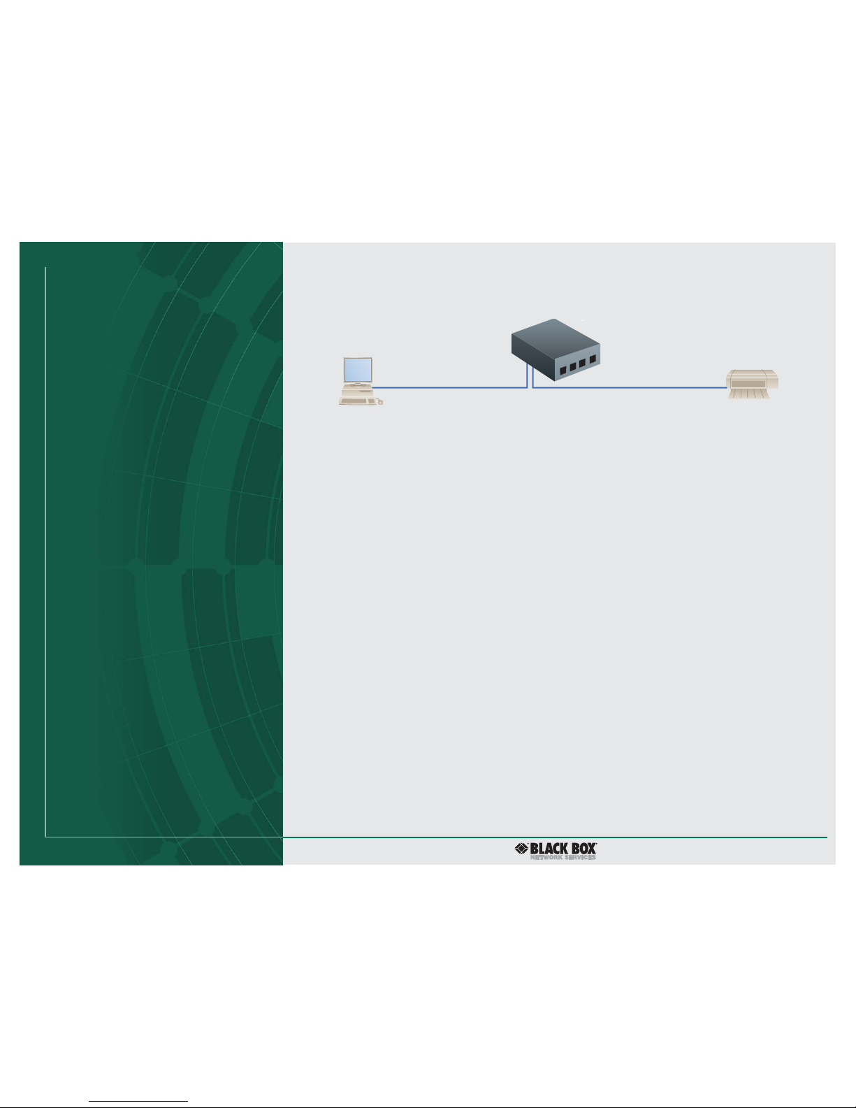
RS-232 PC
232↔488 Interface
Converter
(IC026A-R3)
IEEE 488 printer
or plotter
Up to 4000 ft. (1219.2 m)
Up to 65.6 ft. (20 m)
Connect an RS-232 PC to an IEEE 488 printer or plotter with the converter.
FEATURES
• Requires no programming changes for
most applications.
• Runs at speeds up to 57.6 kbps.
• Interface is RS-232 or RS-422.
OVERVIEW
Whether your industrial applications include oscilloscopes,
meters, plotters, printers, or other industrial equipment,
Black Box has the converter you need.
Imagine being able to control an industrial device from
your RS-232 PC. With the converter, you can attach an RS-232
device to an IEEE 488 device. The distance between the
converter and the IEEE 488 device can be up to 4000 feet
(1219.2 m). The distance between the RS-232 device and the
converter can be up to 65.6 feet (20 m). (See the diagram
pictured above.)
Interconnecting IEEE 488 and serial devices is easy with the
232↔488 Interface Converter. The device can operate in either
of two modes: In controller mode, it enables an RS-232 device
to control an IEEE 488 device, such as a printer or plotter.
In peripheral mode, it can transfer data from an IEEE 488
controller to a serial device.
And because it runs at a wide range of speeds—from
110 bps to 57.6 kbps—it’s flexible for your application.
The converter’s dynamically allocated 32K buffer is there
when and where you need it. It will store data from whichever
port is active. Because no specific buffer is allocated to each
port, no buffer space is wasted and incoming data has access
to storage when it needs it.
The converter’s transparent to data format, so it will work
with spreadsheets (such as Lotus
®
) or CAD programs (such
as AutoCAD
®
).
A self-testing feature checks the microprocessor and
program each time you power on. All you have to do is plug
in the unit and turn on the power. The lights on the front
panel blink once to indicate proper operation. A steady light
indicates a problem area, except for the power light, which
always stays on.
You can run RS-232 or RS-422, so you don’t need another
converter to work with your RS-422 equipment.
And even if you have an older HP
®
74xx or 75xx plotter, the
unit adapts your old plotter to the serial communications port
of your PC.
The converter comes with an external wallmount power
supply (9 VDC) that plugs into the back of the unit.
NOTE: This unit is compatible with any IEEE 488 device except tape
drives, hard drives, or HP 2500, HP 2600, or HP 2900 printers.
Page 3

3 of 4
6/14/07
#10470
724-746-5500 blackbox.com
IEEE 488.
IEEE 488 (also known as GPIB or General Purpose Interface
Bus) is an international standard for a parallel interface
that has greatly simplified the connection of sensors and
programmable instruments to a computer. With it, instruments from different manufacturers can be connected by
a single standard cable.
Two IEEE 488 standards are in use: the older IEEE 488.1
standard, which deals with the hardware only, and the newer
IEEE 488.2 standard, which also addresses software issues like
data formats and error handling.
IEEE 488.1 is a clearly defined mechanical, hardware,
and electrical protocol specification. It doesn’t address data
formats, status reporting, message-exchange protocol, or
common configuration or device-specific commands.
IEEE 488.2 enhances the IEEE 488.1 standard by specifying
data formats, status reporting, error handling, controller
functionality, and common instrument commands. It focuses
mainly on the software protocol issues and thus maintains
compatibility with the hardware-oriented IEEE 488.1
standard. IEEE 488.2 systems tend to be more compatible
and reliable.
Most devices can be adapted to the IEEE 488 specification.
The specification says nothing about the function of the
device itself, or about the form of the device’s data. Instead,
it defines a separate interface that can be added to the
device. Only the signals passing into the interface from the
IEEE 488 bus and from the device are defined in the standard.
There are three classes of devices that can be connected
to the IEEE 488 bus: Listeners, Talkers, and Controllers.
Some devices include more than one of these functions.
The IEEE 488 standard allows a maximum of 15 devices to be
connected on one bus. A minimum system consists of one
Controller and one Talker or Listener device.
A Controller is the device that sends instructions. It’s
possible to have several Controllers on the bus at once but
only one may be active at a time. The Controller that’s in
charge at the moment is called the Active Controller.
The Controller that’s in charge of the entire bus is called
the System Controller. It has several unique capabilities,
including the ability to send Interface Clear (IFC) and Remote
Enable (REN) commands. IFC clears all device interfaces
and returns control to the System Controller. REN allows
devices to respond to bus data once they are addressed to
listen. The System Controller may optionally pass control to
another Controller, which then becomes the Active Controller.
A Listener is a device that can receive data from the bus
when instructed by the Controller. A Talker transmits data on
the bus when instructed. The Controller can set up a Talker
and a group of Listeners to send data between groups of
devices.
The IEEE 488 interface system consists of 16 signal lines
and 8 ground lines. The 16 signal lines are divided into 3
groups (8 data lines, 3 handshake lines, and 5 interfacemanagement lines).
The lines DIO1 through DIO8 are used to transfer
addresses and control information and data. The formats
for addresses and control bytes are defined by the IEEE 488
standard. Data formats are undefined and may be ASCII
or binary. DIO1 is the Least Significant Bit.
The three handshake lines (NRFD, NDAC, DAV) control
the transfer of message bytes among devices and form the
method for acknowledging the transfer of data. This
handshaking process guarantees that bytes on the data lines
are sent and received without any transmission errors. It’s
one of the unique features of the IEEE 488 bus.
The Not Ready for Data (NRFD) handshake line is asserted
by a Listener to indicate it is not yet ready for the next data
or control byte. Note that the Controller will not see NRFD
released (meaning the devices are ready for data) until all
devices have released it.
The Not Data Accepted (NDAC) handshake line is asserted
by a Listener to indicate it has not yet accepted the data or
control byte on the data lines. Note that the Controller will
not see NDAC released (i.e., data accepted) until all devices
have released it.
The Data Valid (DAV) handshake line is asserted by
the Talker to indicate that a data or control byte has been
placed on the data lines and has had the minimum specified
stabilizing time. The byte can now be safely accepted by
the devices.
Five interface management lines (ATN, EOI, IFC, REN, SRQ)
manage the flow of control.
The Attention (ATN) signal is asserted by the Controller
to indicate that it is placing an address or control byte on the
data bus.
The End or Identify (EOI) signal has two uses. A Talker
may assert EOI simultaneously with the last byte of data to
indicate end-of-data. Or the Controller may assert EOI along
with ATN to initiate a parallel poll. Although many devices
do not use parallel poll, all devices should use EOI to end
transfers.
Technically Speaking
Page 4

4 of 4
6/14/07
#10470
724-746-5500 blackbox.com
Item Code
To link an RS-232 device to a 488 bus, order…
232↔488 Interface Converter
IC026A-R3
You may also need…
IEEE 488 Cable (with Molded Connectors)
6.6-ft. (2-m) EXN02M
13.1-ft. (4-m) EXN04M
Individually Shielded Low-Capacitance Cables,
Extra Distance, PVC, 4-Conductor ERN04A
TECH SPECS
General:
Certification — FCC, CE
Data Buffer — 32 KB, dynamically allocated
Data Format — 7 or 8 data bits, 1 or 2 stop bits; parity odd, even, mark,
space, or disabled
User Controls — Power switch (external), IEEE and Serial parameter
switches (internal); Jumper selection of RS-232 or RS-422 operation
(internal)
Interface — IEEE 488; RS-232/RS-422
Indicators — (5) LEDs: Talk, Listen, Send, Receive, Power
Environment — 32 to 122°F (0 to 50°C); Up to 70% to 95°F (35°C) relative
humidity; Linearly derate 3% relative humidity/degrees C from 95 to
122°F (35 to 50°C)
Power — Input: 100–240 VAC, autosensing, 50–60 Hz, 0.5 A maximum;
Output: 9 VDC, 15 W maximum, 1.7 A
Size — 2.7"H x 5.4"W x 7.5"D (6.9 x 13.7 x 19.1 cm)
Weight — 2.5 lb. (1.1 kg);
Power supply: 0.9 lb. (0.4 kg)
IEEE 488 Interface:
Implementation — C1, C2, C3, C4, and C28 controller subsets; Serial to IEEE:
SH1, AH1, T6, TE0, L4, LE0, SR1, RL0, PP0, DC1, DT0, E1
Terminators — Selectable CR, LF, LF-CR, and CR-LF with EOI
Connectors — Standard IEEE 488 connector with metric studs
Serial Interface:
Character Set — Asynchronous bit serial
Data Format — Selectable 7 or 8 data bits; 1 or 2 stop bits; odd, even,
mark, space, and no parity on transmit
Duplex — Full with Echo/No Echo
EIA RS-232C — AB, BA, BB, CA, CB
EIA RS-422A — Balanced voltage on TxD and RxD
Input Voltage — ±3 volts minimum; 15 volts maximum
Output Voltage — ±5 volts minimum (RS-232C); 5 volts typical (RS-422A)
Serial Control — Selectable CTS/RTS or X-ON/X-OFF
Speed — Selectable 110, 300, 600, 1200, 1800, 2400, 3600, 4800, 7200,
9600, 19,200, and 57,600 bps
Terminators — Selectable CR, LF, LF-CR, and CR-LF
Connectors — DB25 male, DCE configured
The Interface Clear (IFC) signal is used by the System
Controller in order to initialize all device interfaces to a
known state.
The Remote Enable (REN) signal is used by the System
Controller. REN enables a device to go into remote mode
when addressed to listen. When in remote mode, a device will
ignore its local front-panel controls.
The Service Request (SRQ) line is like an interrupt: it may
be asserted by any device to request the Controller to take
some action. The Controller must determine which device
is asserting SRQ by conducting a serial poll. The requesting
device releases SRQ when it’s polled.
Recognize any of these situations?
• You wait more than 30 minutes to get through
to a vendor’s tech support.
• The so-called “tech” can’t help you or gives you
the wrong answer.
• You don’t have a purchase order number and the
tech refuses to help you.
• It’s 9 p. m. and you need help, but your vendor’s
tech support line is closed.
According to a survey by Data Communications
magazine, 90% of network managers surveyed say
that getting the technical support they need is extremely
important when choosing a vendor. But even though
network managers pay anywhere from 10 to 20% of their
overall purchase price for a basic service and support
contract, the technical support and service they receive
falls far short of their expectations— and certainly isn’t
worth what they paid.
At Black Box, we guarantee the best value and the
best support. You can even consult our Technical Support
Experts before you buy if you need help selecting just
the right component for your application.
Don’t waste time and money— call Black Box today.
Why Buy From Black Box?
Exceptional Value. Exceptional
Tech Support. Period.
 Loading...