

Page 1
CUSTOMER
SUPPORT
INFORMATION
Order toll-free in the U.S.: Call 877-877-BBOX (outside U.S. call 724-746-5500)
FREE technical support 24 hours a day, 7 days a week: Call 724-746-5500 or fax 724-746-0746
Mailing address: Black Box Corporation, 1000 Park Drive, Lawrence, PA 15055-1018
Web site: www.blackbox.com • E-mail: info@blackbox.com
JANUARY 2001
FX700A
FX701A
FX702A
Voice Pro
Page 2

1
FCC INFORMATION
FEDERAL COMMUNICATIONS COMMISSION
AND
INDUSTRY CANADA
RADIO FREQUENCY INTERFERENCE STATEMENTS
This equipment generates, uses, and can radiate radio frequency energy and if not
installed and used properly, that is, in strict accordance with the manufacturer’s
instructions, may cause interference to radio communication. It has been tested
and found to comply with the limits for a Class A computing device in accordance
with the specifications in Subpart J of Part 15 of FCC rules, which are designed to
provide reasonable protection against such interference when the equipment is
operated in a commercial environment. Operation of this equipment in a
residential area is likely to cause interference, in which case the user at his own
expense will be required to take whatever measures may be necessary to correct
the interference.
Changes or modifications not expressly approved by the party responsible
for compliance could void the user’s authority to operate the equipment.
This digital apparatus does not exceed the Class A limits for radio noise emission from
digital apparatus set out in the Radio Interference Regulation of Industry Canada.
Le présent appareil numérique n’émet pas de bruits radioélectriques dépassant les limites
applicables aux appareils numériques de la classe A prescrites dans le Règlement sur le
brouillage radioélectrique publié par Industrie Canada.
Page 3

2
VOICE PRO
FCC REQUIREMENTS FOR
TELEPHONE-LINE EQUIPMENT
1. The Federal Communications Commission (FCC) has established rules which
permit this device to be directly connected to the telephone network with
standardized jacks. This equipment should not be used on party lines or coin
lines.
2. If this device is malfunctioning, it may also be causing harm to the telephone
network; this device should be disconnected until the source of the problem
can be determined and until the repair has been made. If this is not done, the
telephone company may temporarily disconnect service.
3. If you have problems with your telephone equipment after installing this
device, disconnect this device from the line to see if it is causing the problem.
If it is, contact your supplier or an authorized agent.
4. The telephone company may make changes in its technical operations and
procedures. If any such changes affect the compatibility or use of this device,
the telephone company is required to give adequate notice of the changes.
5. If the telephone company requests information on what equipment is
connected to their lines, inform them of:
a. The telephone number that this unit is connected to.
b. The ringer equivalence number.
c. The USOC jack required: RJ-11C.
d. The FCC registration number.
Items (b) and (d) can be found on the unit’s FCC label. The ringer
equivalence number (REN) is used to determine how many devices can be
connected to your telephone line. In most areas, the sum of the RENs of all
devices on any one line should not exceed five (5.0). If too many devices are
attached, they may not ring properly.
6. In the event of an equipment malfunction, all repairs should be performed by
your supplier or an authorized agent. It is the responsibility of users requiring
service to report the need for service to the supplier or to an authorized
agent.
Page 4

3
INDUSTRY CANADA CERTIFICATION NOTICE
CERTIFICATION NOTICE FOR
EQUIPMENT USED IN CANADA
The Industry Canada label identifies certified equipment. This certification means
that the equipment meets certain telecommunications-network protective,
operation, and safety requirements. Industry Canada does not guarantee the
equipment will operate to the user’s satisfaction.
Before installing this equipment, users should ensure that it is permissible to be
connected to the facilities of the local telecommunications company. The
equipment must also be installed using an acceptable method of connection. In
some cases, the company’s inside wiring associated with a single-line individual
service may be extended by means of a certified connector assembly (extension
cord). The customer should be aware that compliance with the above conditions
may not prevent degradation of service in some situations.
Repairs to certified equipment should be made by an authorized maintenance
facility—in this case, Black Box. Any repairs or alterations made by the user to this
equipment, or equipment malfunctions, may give the telecommunications
company cause to request the user to disconnect the equipment.
Users should ensure for their own protection that the electrical ground
connections of the power utility, telephone lines, and internal metallic water pipe
system, if present, are connected together. This precaution may be particularly
important in rural areas.
CAUTION:
Users should not attempt to make such connections themselves, but
should contact the appropriate electric inspection authority, or
electrician, as appropriate.
The LOAD NUMBER (LN) assigned to each terminal device denotes the
percentage of the total load to be connected to a telephone loop which is used by
the device, to prevent overloading. The termination on a loop may consist of any
combination of devices, subject only to the requirement that the total of the load
numbers of all the devices does not exceed 100.
Page 5

4
VOICE PRO
NORMAS OFICIALES MEXICANAS (NOM)
ELECTRICAL SAFETY STATEMENT
INSTRUCCIONES DE SEGURIDAD
1. Todas las instrucciones de seguridad y operación deberán ser leídas antes de
que el aparato eléctrico sea operado.
2. Las instrucciones de seguridad y operación deberán ser guardadas para
referencia futura.
3. Todas las advertencias en el aparato eléctrico y en sus instrucciones de
operación deben ser respetadas.
4. Todas las instrucciones de operación y uso deben ser seguidas.
5. El aparato eléctrico no deberá ser usado cerca del agua—por ejemplo, cerca
de la tina de baño, lavabo, sótano mojado o cerca de una alberca, etc..
6. El aparato eléctrico debe ser usado únicamente con carritos o pedestales que
sean recomendados por el fabricante.
7. El aparato eléctrico debe ser montado a la pared o al techo sólo como sea
recomendado por el fabricante.
8. Servicio—El usuario no debe intentar dar servicio al equipo eléctrico más allá
a lo descrito en las instrucciones de operación. Todo otro servicio deberá ser
referido a personal de servicio calificado.
9. El aparato eléctrico debe ser situado de tal manera que su posición no
interfiera su uso. La colocación del aparato eléctrico sobre una cama, sofá,
alfombra o superficie similar puede bloquea la ventilación, no se debe colocar
en libreros o gabinetes que impidan el flujo de aire por los orificios de
ventilación.
10. El equipo eléctrico deber ser situado fuera del alcance de fuentes de calor
como radiadores, registros de calor, estufas u otros aparatos (incluyendo
amplificadores) que producen calor.
11. El aparato eléctrico deberá ser connectado a una fuente de poder sólo del
tipo descrito en el instructivo de operación, o como se indique en el aparato.
Page 6

5
NOM STATEMENT
12. Precaución debe ser tomada de tal manera que la tierra fisica y la polarización
del equipo no sea eliminada.
13. Los cables de la fuente de poder deben ser guiados de tal manera que no
sean pisados ni pellizcados por objetos colocados sobre o contra ellos,
poniendo particular atención a los contactos y receptáculos donde salen del
aparato.
14. El equipo eléctrico debe ser limpiado únicamente de acuerdo a las
recomendaciones del fabricante.
15. En caso de existir, una antena externa deberá ser localizada lejos de las lineas
de energia.
16. El cable de corriente deberá ser desconectado del cuando el equipo no sea
usado por un largo periodo de tiempo.
17. Cuidado debe ser tomado de tal manera que objectos liquidos no sean
derramados sobre la cubierta u orificios de ventilación.
18. Servicio por personal calificado deberá ser provisto cuando:
A: El cable de poder o el contacto ha sido dañado; u
B: Objectos han caído o líquido ha sido derramado dentro del aparato; o
C: El aparato ha sido expuesto a la lluvia; o
D: El aparato parece no operar normalmente o muestra un cambio en su
desempeño; o
E: El aparato ha sido tirado o su cubierta ha sido dañada.
Page 7

6
VOICE PRO
TRADEMARKS USED IN THIS MANUAL
Any trademarks mentioned in this manual are acknowledged to be the property of the
trademark owners.
Page 8

7
CONTENTS
Contents
Chapter Page
Quick Start Guide . . . . . . . . . . . . . . . . . . . . . . . . . . . . . . . . . . . . . . . . . . . . 10
1. Specifications. . . . . . . . . . . . . . . . . . . . . . . . . . . . . . . . . . . . . . . . . . . . . . 17
2. Introduction . . . . . . . . . . . . . . . . . . . . . . . . . . . . . . . . . . . . . . . . . . . . . . 18
2.1 Overview. . . . . . . . . . . . . . . . . . . . . . . . . . . . . . . . . . . . . . . . . . . . . . . 18
2.2 Preparing for Installation . . . . . . . . . . . . . . . . . . . . . . . . . . . . . . . . . 18
2.3 Power Supply . . . . . . . . . . . . . . . . . . . . . . . . . . . . . . . . . . . . . . . . . . . 19
2.4 Telephone Company (CO) Lines . . . . . . . . . . . . . . . . . . . . . . . . . . 19
2.5 Telephone Extensions . . . . . . . . . . . . . . . . . . . . . . . . . . . . . . . . . . . 19
2.6 Key System or PBX . . . . . . . . . . . . . . . . . . . . . . . . . . . . . . . . . . . . . . 20
2.7 Additional Installation Items . . . . . . . . . . . . . . . . . . . . . . . . . . . . . . 20
2.8 Optional Equipment . . . . . . . . . . . . . . . . . . . . . . . . . . . . . . . . . . . . . 20
3. Installation . . . . . . . . . . . . . . . . . . . . . . . . . . . . . . . . . . . . . . . . . . . . . . . . 21
3.1 Overview. . . . . . . . . . . . . . . . . . . . . . . . . . . . . . . . . . . . . . . . . . . . . . . 21
3.2 Connecting the Telephone Company Lines. . . . . . . . . . . . . . . . . . 22
3.2.1 Voice Pro 2 x 6 (FX700A) Configuration . . . . . . . . . . . . . . . . 22
3.2.2 Voice Pro 4 x 8 (FX701A) Configuration . . . . . . . . . . . . . . . . 22
3.2.3 Voice Pro 4 x 12 (FX702A) Configuration . . . . . . . . . . . . . . . 23
3.3 Connecting the Station Ports . . . . . . . . . . . . . . . . . . . . . . . . . . . . . . 23
3.3.1 Equipment Connections . . . . . . . . . . . . . . . . . . . . . . . . . . . . . 23
3.3.2 Key System or PBX Connections . . . . . . . . . . . . . . . . . . . . . . . 24
3.4 Connecting a Computer or Fax Machine . . . . . . . . . . . . . . . . . . . . 24
3.5 Installing the Power Supply . . . . . . . . . . . . . . . . . . . . . . . . . . . . . . . 25
3.6 System Startup . . . . . . . . . . . . . . . . . . . . . . . . . . . . . . . . . . . . . . . . . . 26
3.7 Installing an External Music Source . . . . . . . . . . . . . . . . . . . . . . . . 27
3.8 Battery Backup. . . . . . . . . . . . . . . . . . . . . . . . . . . . . . . . . . . . . . . . . . 27
3.9 Voice Pro Indicators and Buttons . . . . . . . . . . . . . . . . . . . . . . . . . . 28
3.9.1 Top Panel Indicators . . . . . . . . . . . . . . . . . . . . . . . . . . . . . . . . 28
3.9.2 Hardware Reset Button . . . . . . . . . . . . . . . . . . . . . . . . . . . . . . 28
4. Programming the Voice Pro System . . . . . . . . . . . . . . . . . . . . . . . . . . . 29
4.1 Quick Reference Program Guide. . . . . . . . . . . . . . . . . . . . . . . . . . . 29
4.2 Quick Start: Program Your Voice Pro System . . . . . . . . . . . . . . . . . 30
4.3 Program Your Voice Pro from a Remote
Touch-tone Telephone . . . . . . . . . . . . . . . . . . . . . . . . . . . . . . . . . . . 33
4.4 Voice Pro System Program Guide . . . . . . . . . . . . . . . . . . . . . . . . . . 33
Page 9

8
VOICE PRO
Chapter Page
4.5 System Operating Tips . . . . . . . . . . . . . . . . . . . . . . . . . . . . . . . . . . . 56
4.6 Auto Attendant Mode . . . . . . . . . . . . . . . . . . . . . . . . . . . . . . . . . . . . 58
4.7 Key System or PBX Operation . . . . . . . . . . . . . . . . . . . . . . . . . . . . . 59
4.7.1 Ringing Assignments . . . . . . . . . . . . . . . . . . . . . . . . . . . . . . . . 59
4.7.2 Standard Operation . . . . . . . . . . . . . . . . . . . . . . . . . . . . . . . . . 59
5. Using the Voice Pro System . . . . . . . . . . . . . . . . . . . . . . . . . . . . . . . . . . 60
5.1 To Make a Call. . . . . . . . . . . . . . . . . . . . . . . . . . . . . . . . . . . . . . . . . . 60
5.2 Flash Key . . . . . . . . . . . . . . . . . . . . . . . . . . . . . . . . . . . . . . . . . . . . . . 62
5.3 Call Waiting . . . . . . . . . . . . . . . . . . . . . . . . . . . . . . . . . . . . . . . . . . . . 63
5.4 Call Pickup . . . . . . . . . . . . . . . . . . . . . . . . . . . . . . . . . . . . . . . . . . . . . 64
5.5 Conference Calls . . . . . . . . . . . . . . . . . . . . . . . . . . . . . . . . . . . . . . . . 64
5.6 Door Chime Box . . . . . . . . . . . . . . . . . . . . . . . . . . . . . . . . . . . . . . . . 67
5.7 Fax Switching . . . . . . . . . . . . . . . . . . . . . . . . . . . . . . . . . . . . . . . . . . . 68
5.8 Place a Call on Hold . . . . . . . . . . . . . . . . . . . . . . . . . . . . . . . . . . . . . 69
5.9 Hold Recall . . . . . . . . . . . . . . . . . . . . . . . . . . . . . . . . . . . . . . . . . . . . 69
5.10 Call Screening . . . . . . . . . . . . . . . . . . . . . . . . . . . . . . . . . . . . . . . . . 70
5.10.1 How Does Call Screening Work? . . . . . . . . . . . . . . . . . . . . . . 70
5.10.2 Enable/Disable Call Screening (Local) . . . . . . . . . . . . . . . . 71
5.10.3 Enable Call Screening (Remote). . . . . . . . . . . . . . . . . . . . . . 71
5.10.4 Disable Call Screening (Remote) . . . . . . . . . . . . . . . . . . . . . 71
5.11 Call Transfer . . . . . . . . . . . . . . . . . . . . . . . . . . . . . . . . . . . . . . . . . . 71
5.11.1 Announced Transfer . . . . . . . . . . . . . . . . . . . . . . . . . . . . . . . 72
5.11.2 Unannounced Transfer . . . . . . . . . . . . . . . . . . . . . . . . . . . . . 72
5.11.3 Transfer to a Voice Mailbox. . . . . . . . . . . . . . . . . . . . . . . . . . 72
5.12 Paging. . . . . . . . . . . . . . . . . . . . . . . . . . . . . . . . . . . . . . . . . . . . . . . . 73
5.13 Call Forwarding . . . . . . . . . . . . . . . . . . . . . . . . . . . . . . . . . . . . . . . . 73
5.14 Intercom Calls . . . . . . . . . . . . . . . . . . . . . . . . . . . . . . . . . . . . . . . . . 75
5.14.1 Placing an Intercom Call . . . . . . . . . . . . . . . . . . . . . . . . . . . . 75
5.14.2 Receiving an Intercom Call . . . . . . . . . . . . . . . . . . . . . . . . . . 75
5.15 Music on Hold . . . . . . . . . . . . . . . . . . . . . . . . . . . . . . . . . . . . . . . . . 75
5.16 Virtual Extensions . . . . . . . . . . . . . . . . . . . . . . . . . . . . . . . . . . . . . . 76
5.17 Two-Way Recording . . . . . . . . . . . . . . . . . . . . . . . . . . . . . . . . . . . . 77
5.18 Access Your Voice Mailbox . . . . . . . . . . . . . . . . . . . . . . . . . . . . . . . 78
5.19 Voice Mailbox Options . . . . . . . . . . . . . . . . . . . . . . . . . . . . . . . . . . 79
5.20 Program Your Voice Mailbox . . . . . . . . . . . . . . . . . . . . . . . . . . . . . 85
5.20.1 Changing Your Password . . . . . . . . . . . . . . . . . . . . . . . . . . . . 85
5.20.2 Recording Your Personal Greeting . . . . . . . . . . . . . . . . . . . . 86
5.20.3 Programming Message Alert . . . . . . . . . . . . . . . . . . . . . . . . . 86
5.20.4 Disabling Message Alert . . . . . . . . . . . . . . . . . . . . . . . . . . . . . 87
Page 10

9
CONTENTS
Chapter Page
5.21 Caller Options . . . . . . . . . . . . . . . . . . . . . . . . . . . . . . . . . . . . . . . . . 87
5.21.1 Direct Dialing an Extension. . . . . . . . . . . . . . . . . . . . . . . . . . 88
5.21.2 Accessing the Phone Directory . . . . . . . . . . . . . . . . . . . . . . . 88
5.21.3 Access a Voice Mailbox and Leave a Message. . . . . . . . . . . . 88
5.22 Additional Tips for Using the System . . . . . . . . . . . . . . . . . . . . . . 90
5.22.1 Accessing Telephone Company Features . . . . . . . . . . . . . . . 90
5.22.2 Using the Speed Dial Feature . . . . . . . . . . . . . . . . . . . . . . . . 90
Appendix: Programming Changes Record . . . . . . . . . . . . . . . . . . . . . . . . 91
Page 11

10
VOICE PRO
Quick Start Guide
Step 1: Remove the contents from the box.
You should have received:
• Voice Pro system
• Power supply (wall-mounted transformer that plugs into an AC outlet)
• This users’ manual
• Double-ended, 7-ft. (2.1-m) line cords ([2] for FX700A, [6] for FX701A and
FX702A)
• 6-in. (15.2-cm) line cords ([2] for FX700A, [4] for FX701A and FX702A)
• Line splitter that plugs into a phone jack ([1] for FX700A, [2] for FX701A
and FX702A)
• Extension splitter that allows a 2-line phone to plug into two extensions on
the Voice Pro ([1] for FX7000A, [2] for FX701A and FX702A)
• (1) 6-ft. (1.8-m) double-ended 3.5-mm music cord
• (1) template to wallmount the Voice Pro
Step 2: Power on the Voice Pro.
a. Place the Voice Pro on the desk or (using the wallmount template) mount
the Voice Pro on the wall.
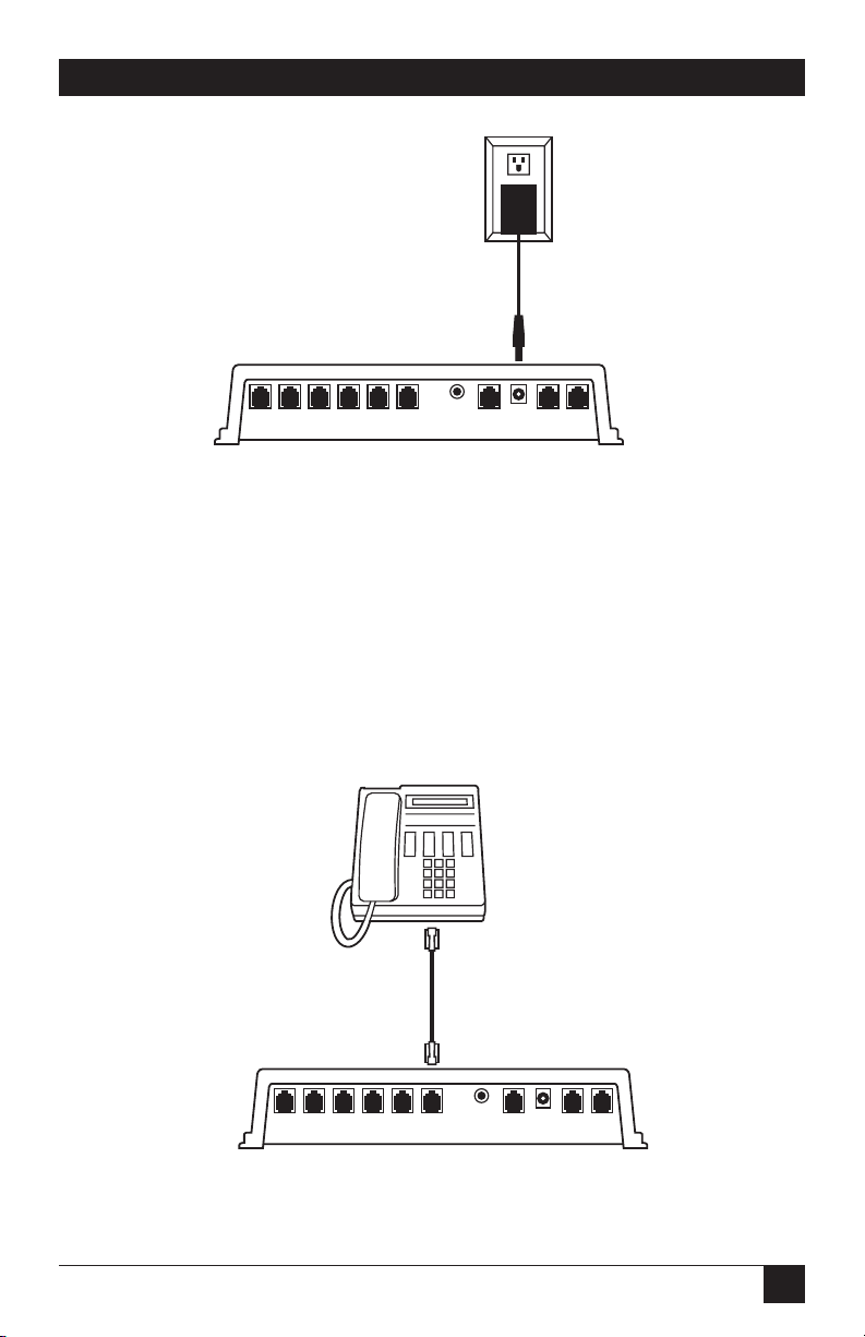
b. Plug the power supply into an AC outlet. Connect the male connector to the
power jack on the rear of the Voice Pro system (see Figure Q-1).
c. After connecting the power supply, the red power LED should light, and the
green LED should flash.
Page 12
11
QUICK START GUIDE
Figure Q-1. Powering up the Voice Pro.
Step 3: Connect one-line telephones to the Voice Pro.
The Voice Pro system supports up to six telephone extensions.
Single- (one-) line telephones plug directly into the desired jack on the Voice Pro
(see Figure Q-2).
As many as six devices may be connected. Devices may inlude corded or cordless
phones, fax machines, or even credit-card machines.
Figure Q-2. Connecting a one-line telephone to the Voice Pro.
Ext 15 Ext 14 Ext 13 Ext 12 Ext 11 Ext 10 Music RS 232 Pwr Line 2 Line 1
Ext 15 Ext 14 Ext 13 Ext 12 Ext 11 Ext 10 Music RS 232 Pwr Line 2 Line 1
Page 13
12
VOICE PRO
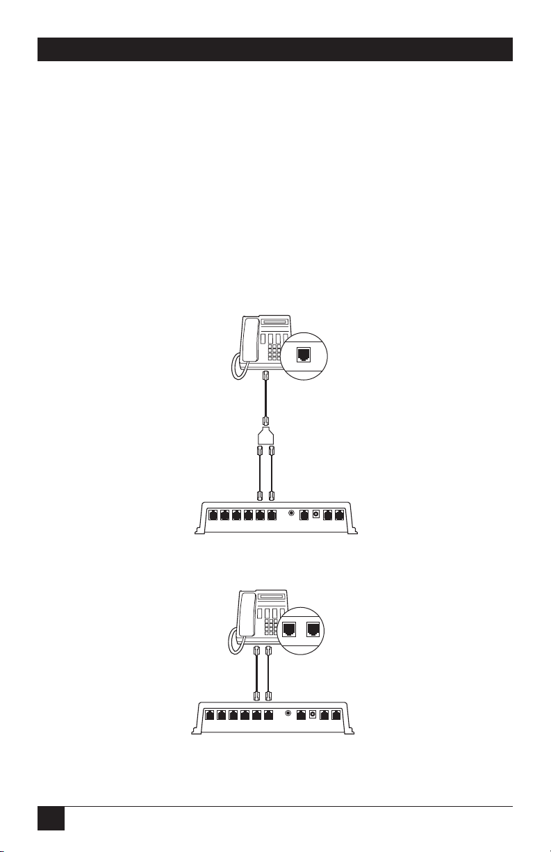
Step 4: Connect two-line telephones to the Voice Pro.
If you are connecting a two-line telephone to the Voice Pro, follow these steps:
a. If your two-line telephone has one jack on the back of the telephone, connect
a line cord to the rear of the telephone. Connect the other end of the line
cord to the splitter.
Use the two 6-inch (15.2-cm) line cords to connect to the splitter, and then to the
desired extensions of the Voice Pro (see Figure Q-3).
b. If your two-line telephone has two jacks on the back of the telephone,
connect two line cords from the telephone to the desired extension jacks on
the Voice Pro (see Figure Q-4).
Figure Q-3. Connecting two-line telephones with one jack to the Voice Pro.
Figure Q-4. Connecting the two-line telephone
with two jacks to the Voice Pro.
L1/L2
Ext 15 Ext 14 Ext 13 Ext 12 Ext 11 Ext 10 Music RS 232 Pwr Line 2 Line 1
L1/L2 L2
Ext 15 Ext 14 Ext 13 Ext 12 Ext 11 Ext 10 Music RS 232 Pwr Line 2 Line 1
Page 14
13
QUICK START GUIDE
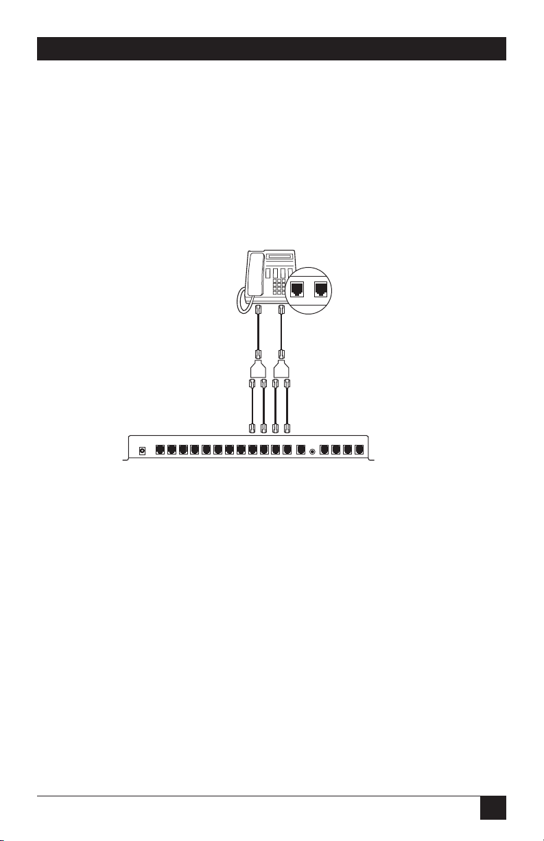
Step 5: Connect four-line telephones to the Voice Pro 4 x 8 and 4 x 12
(FX701A and FX702A).
Connect both line cords from your phone to the line splitters as shown in Figure
Q-5. Then, using the four 6-inch (15.2-cm) cords included, connect them from the
splitters to the desired extensions on the Voice Pro.
NOTE
If you have a Voice Pro 2 x 6 (FX700A), skip this step.
Figure Q-5. Connecting four-line telephones to the Voice Pro.
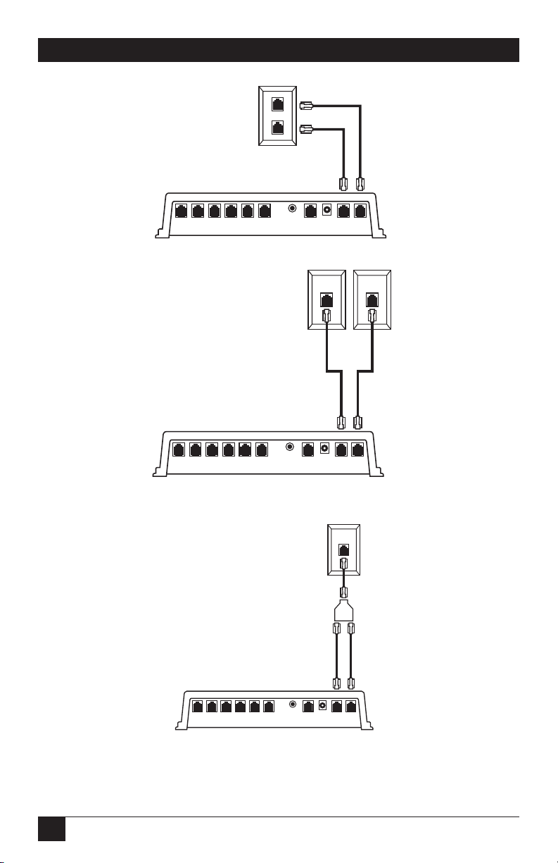
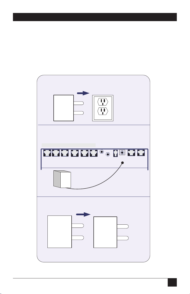
Step 6: Connect telephone lines to the Voice Pro.
The Voice Pro can support two (FX700A) or four (FX701A and FX702A)
incoming telephone lines.
If you are attaching two incoming telephone lines to your Voice Pro, follow one of
the next three diagrams, depending on the configuration of your telephone jacks.
L1/L2 L3/L4
Power
ST 15 ST 14 ST 13 ST 12 ST 11 ST 10
RS 232
CO 3 CO 4ST 21 ST 20 ST 19 ST 18 ST 17 ST 16 CO 1 CO 2
Music
Page 15
14
VOICE PRO
Figure Q-6. Connecting two telephone lines to the Voice Pro, example 1.
Figure Q-7. Connecting two telephone lines to the Voice Pro, example 2.
Figure Q-8. Connecting two telephone lines to the Voice Pro, example 3.
If you have a FX701A or FX702A, you can attach up to four incoming lines (twice
those shown in the diagrams) to the system.
L1
L2
Ext 15 Ext 14 Ext 13 Ext 12 Ext 11 Ext 10 Music RS 232 Pwr Line 2 Line 1
L2 L1
Ext 15 Ext 14 Ext 13 Ext 12 Ext 11 Ext 10 Music RS 232 Pwr Line 2 Line 1
L1/L2
Ext 15 Ext 14 Ext 13 Ext 12 Ext 11 Ext 10 Music RS 232 Pwr Line 2 Line 1
Page 16

15
QUICK START GUIDE
Step 7: Connect a music source.
Use the included 6-ft. (1.8-m) cable with 3.5-mm headphone jacks at each end to
connect a music source to the Voice Pro. Connect one end of the cable to the
music jack on the Voice Pro and the other end to the music source (radio, CD
player, etc.).
Figure Q-9. Connecting a music source to the Voice Pro.
Step 8: Program the Voice Pro.
1. Connect the telephone lines and install the telephone extensions before
programming the Voice Pro.
2. From any station, lift the receiver and press the # key. You will hear the
automated voice say “Welcome to Voice Pro.”
3. Enter the 4-digit default password (the default password is 1234), then enter
the # key.
4. Program the lines installed (press 2, then the # key).
a. If one line is installed, press 1, then the # key).
b. If two lines are installed, press 1, then 2, then the # key.
5. Set the clock.
While still in programming mode, press 1, then 9, then the # key.
Enter the hour, for example, 8 or 12—followed by the # key.
Enter the minute (2 digits; for example, 05 or 36) followed by the # key.
Ext 15 Ext 14 Ext 13 Ext 12 Ext 11 Ext 10 Music RS 232 Pwr Line 2 Line 1
Page 17

16
VOICE PRO
Enter 1 for AM or 2 for PM. Press the # key.
6. Set the date.
While still in programming mode, press 20 followed by the # key.
Enter the month (one or two digits; for example, press 3 for March, 11 for
November) followed by the # key.
Enter the day of the month (1–31) followed by the # key.
Enter the year (for example, 00 for 2000) followed by the # key.
Enter the number for the day of the week followed by the # key. (1 for
Monday, 2 for Tuesday, 3 for Wednesday, 4 for Thursday, 5 for Friday, 6 for
Saturday or 7 for Sunday).
7. Record the main greeting (the recording that plays when someone calls, also
known as the auto-attendant).
While still in programming mode, press 21 followed by the # key. Begin your
greeting after the tone.
A sample greeting might sound like this: “Thank you for calling ABC company. If you
know your party’s extension number, you may press it at any time, or press 0 to speak to
the operator. Thanks again for calling!”
When you are finished recording, press the # key.
8. To exit programming mode, press **. Refer to the Chapter 4 for additional
programming options.
Page 18

17
CHAPTER 1: Specifications
1. Specifications
Interface—Public Switched Telephone Network (PSTN)
Line Type—2-wire analog dialup
Operation—Full duplex
Indicators—(3) LEDs: Power, In-Use, Full
Connectors—FX700A: (6) RJ-11 for equipment connections, (2) RJ-11 for line
connections, (1) RJ-11 for software development (not used);
FX701A: (8) RJ--11 for equipment connections, (4) RJ-11 for line connections,
(1) RJ-11 for software development (not used);
FX702A: (12) RJ-11 for equipment connections, (4) RJ-11 for line connections,
(1) RJ-11 for software development (not used)
Power—In: 120 VAC, 60 Hz, 24 amps; Out: 28 VDC, 600 mA
Size—FX700A: 2.3"H x 8.7"W x 9.9"D (5.8 x 22.1 x 25.1 cm);
FX701A, FX702A: 1.9"H x 7"W x 11.7"D (4.8 x 17.8 x 29.7 cm)
Weight—FX700A: 2.5 lb. (1.1 kg); FX701A, FX702A: 4 lb. (1.8 kg)
Page 19

18
VOICE PRO
2. Introduction
2.1 Overview
The Voice Pro combines a voice-mail system and a digital hybrid telephone switch.
This means that you can use the Voice Pro as a standalone system or ahead of any
existing PBX or key telephone system.
Your Voice Pro system is designed for the small-office/home-office customer.
Included in your Voice Pro system are features normally found on a larger and
more expensive PBX and voice-mail system designed for medium to large-size
businesses.
The Voice Pro’s custom-designed features make it a snap to install and use. With
the touch of a key, all of the advanced features are literally at your fingertips.
With simple programming, you have access to:
• call screening,
• pager notification,
• message waiting and retrieval,
• intercom,
• conference,
• auto-attendant,
• and much more!
NOTE
To obtain the full benefits from your Voice Pro system, please read
through the installation and operating instructions, and keep them
handy for future reference.
2.2 Preparing for Installation
Before installing your Voice Pro system, you must have all of the necessary tools
and equipment on hand. You will need your Voice Pro system, the power supply
(included), and the telephones you want to install. (Fax machines and computers
can also be installed.)
Page 20
19
CHAPTER 2: Introduction
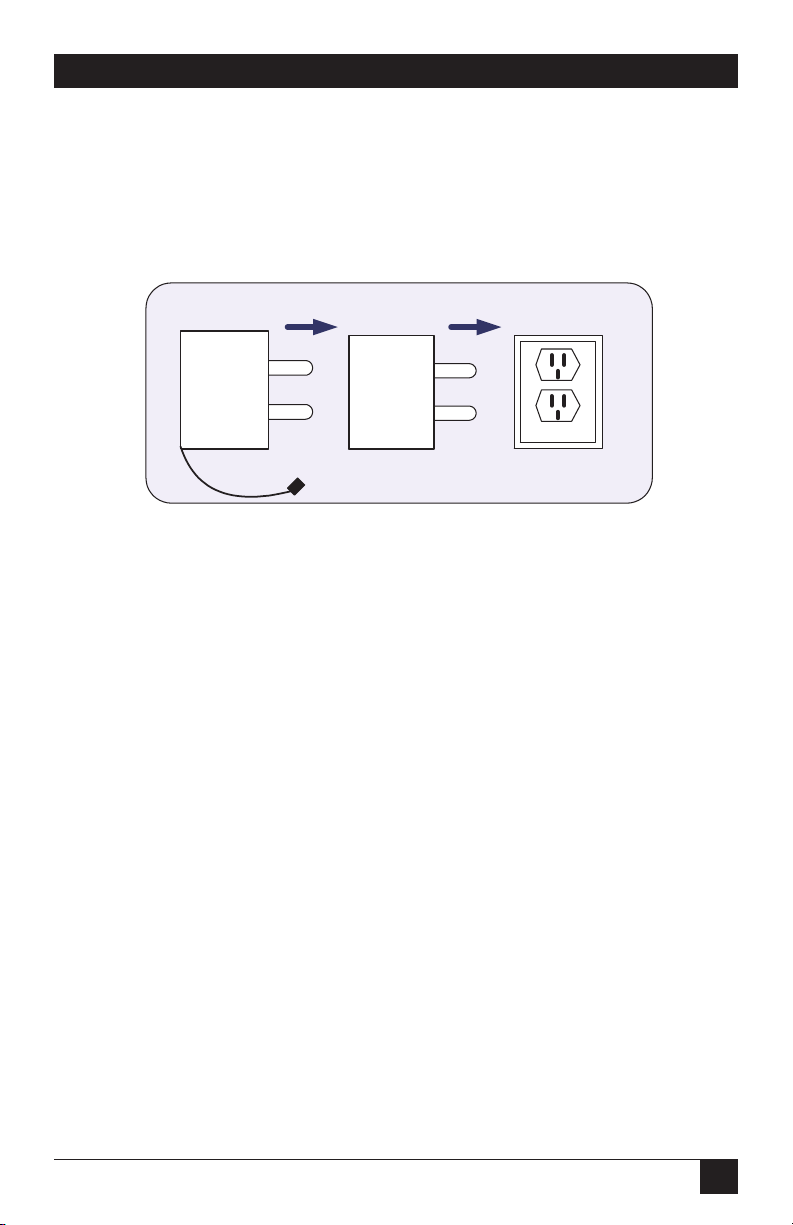
2.3 Power Supply
A 120-VAC power supply is provided. We strongly recommend that you install a
surge protector at the dedicated outlet for the Voice Pro. This will protect the
system from a sudden increase in voltage (for example, during a thunderstorm).
Figure 2-1. Power-supply configuration.
2.4 Telephone Company (CO) Lines
The Voice Pro systems are equipped to handle up to four outside lines.
2.5 Telephone Extensions
• The Voice Pro 2 x 6 (FX700A) supports up to six extensions (station numbers
10–15).
• The Voice Pro 4 x 8 (FX701A) supports up to eight extensions (station
numbers 10–17).
• The Voice Pro 4 x 12 (FX702A) supports up to twelve extensions (station
numbers 10–21).
• All Voice Pro systems are designed to work with most off-the-shelf telephone
sets, fax machines, computers, and cordless telephones.
NOTES
Each station port has a 24-VDC talk battery and 80 V RMS @ 0.4 A/20 Hz
ringing.
Some KSU-less telephone-system phones may not be compatible with
the Voice Pro.
Recommended power supply configuration
Power
supply unit
To VP Unit
Surge
protector
120 Volts
Page 21

20
VOICE PRO
2.6 Key System or PBX
• The Voice Pro 2 x 6 (FX700A) can be installed ahead of any key or PBX system
or standalone.
• The Voice Pro 4 x 8 or 4 x 12 (FX701A or FX702A) may also be installed
ahead of any key system or PBX. You will receive optimum benefits using the
FX701A or FX702A as a standalone PBX/voice-mail system.
2.7 Additional Installation Items
• A dedicated 120-VAC outlet or extension-cord jack must be located within
6 feet (1.8 m) of the Voice Pro, and within 25 feet (7.6 m) of the line
connections. If you need additional distance, contact your telephone company
to have the lines reinstalled for easier access to your Voice Pro.
• Standard telephone cables with RJ-11 plugs on each end are required for the
extension telephones. These cables will most likely be included with your
telephone sets.
2.8 Optional Equipment
• Music on hold: You can connect a radio or other music source to the system to
provide music to callers on hold.
WARNING
DO NOT plug the music source into an extension port on the rear of the
Voice Pro unit. This will permanently damage the Voice Pro.
• Door chime box: You can install a separate door chime box so that you can
communicate through a station connected to your Voice Pro with a guest
ringing your doorbell. We recommend that a professional telecommunication
vendor install hardware for the door chime box.
Page 22

21
CHAPTER 3: Installation
3. Installation
3.1 Overview
You can begin using your Voice Pro system in just minutes by following these four
easy steps.
1. Connect the telephone company lines to the Voice Pro’s rear panel.
2. Connect your telephones and other equipment to the extension ports.
3. Install the power supply to the Voice Pro.
4. Install an external music source (optional).
NOTE
Installation procedures for all Voice Pro models are the same. The
FX701A has two additional station ports, and the FX702A has six
additional station ports for added telephones or other equipment. The
FX701A and FX702A both have two additional telephone line jacks as
well.
Depending upon the unit you purchased, you can have anywhere from 1 to 4
incoming lines. The available Voice Pro systems are described in Table 3-1.
Table 3-1. Available Voice Pro systems
System Telephone Message Valid Number of
Model Co./Station Length Station Mailboxes
Lines Options Number
(hours)
FX700A 2 x 6 2, 4, 8 10–15 85
FX701A 4 x 8 2, 4, 8 10–17 85
FX702A 4 x 12 2, 4, 8 10–21 85
Page 23
22
VOICE PRO
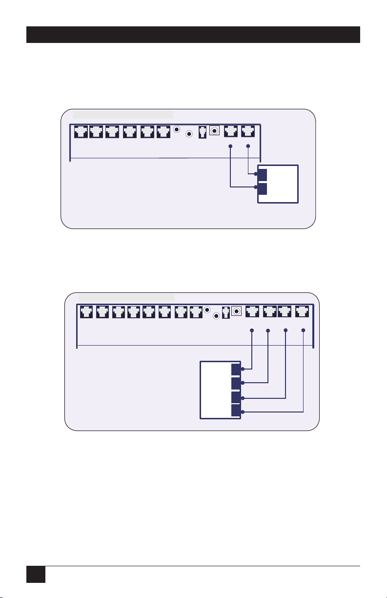
3.2 Connecting the Telephone Company Lines
3.2.1 V
OICEPRO2 X
6 (FX700A) C
ONFIGURATION
Figure 3-1. Voice Pro 2 x 6 configuration.
3.2.2 V
OICEPRO4 X
8 (FX701A) C
ONFIGURATION
Figure 3-2. Voice Pro 4 x 8 configuration.
Voice Pro 2 x 6 Rear Panel
Voice Pro 4 x 8 Rear Panel
Voice Pro
1.
into the connector on the VP unit marked
Line 1.
2.
company jack, which is to be Line 1.
3.
Voice Pro-206 Series Rear Panel
Ext13
Ext14Ext15
Ext12
Ext11 Ext10
Reset
Music
RS232
Plug one end of a modular line cord
Plug the other end into the telephone
Repeat Steps 1 & 2 for Line 2.
Voice Pro-408 Series Rear Panel
Ext16
Ext15 Ext14
Ext17
Ext12
Ext11 Ext10
Ext13
Reset
Pwr
Music
Line 2 Line 1
RS232
Pwr
Line 4 Line 3
Line 1
Line 2
Line 2 Line 1
Voice Pro
1.
Plug one end of a modular line cord
into the connector on the VP unit marked
Line 1.
2.
Plug the other end into the telephone
company jack, which is to be Line 1.
3.
Repeat Steps 1 & 2 for Lines 2
through 4.
Line 4
Line 3
Line 2
Line 1
Page 24

23
CHAPTER 3: Installation
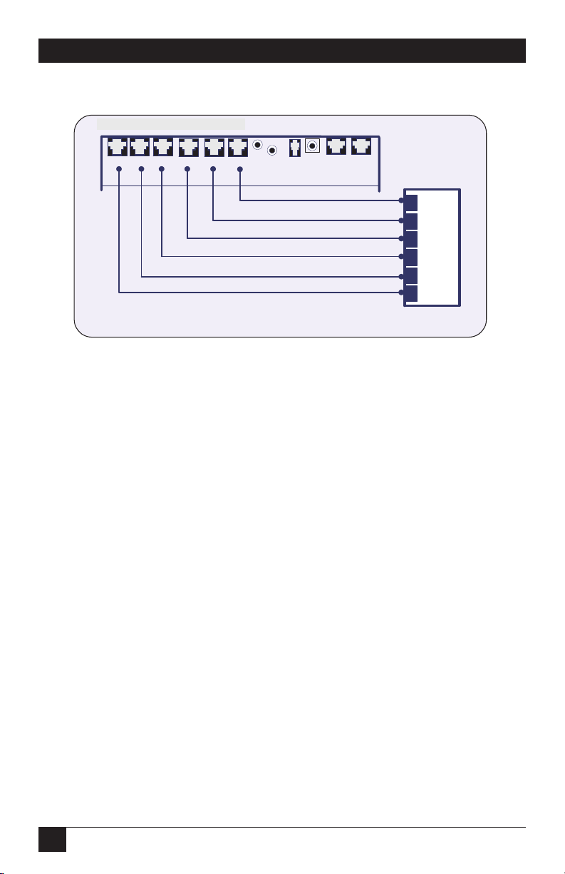
3.2.3 V
OICEPRO4 X
12 (FX702A) C
ONFIGURATION
Figure 3-3. Voice Pro 4 x 12 configuration.
WARNING
DO NOT connect a telephone line to a station port. This will cause
permanent damage to the Voice Pro.
NOTE
Installation procedures for all Voice Pro models are the same. The
FX701A and FX702A have two additional telephone lines.
3.3 Connecting the Station Ports
3.3.1 E
QUIPMENTCONNECTIONS
Figure 3-4. Equipment connections.
Voice Pro 4 x 12 Rear Panel
Voice Pro 2 x 6 Rear Panel
1.
into the connector on the VP unit marked
Line 1.
2.
company jack, which is to be Line 1.
3.
through 4.
Voice Pro-412 Series Rear Panel
Ext19Ext
Ext
17
18
Ext
21
Voice Pro
Ext
20
Ext15Ext
Ext
16
Ext
Ext
13
14
12
Plug one end of a modular line cord
Plug the other end into the telephone
Repeat Steps 1 & 2 for Lines 2
Ext11Ext
Reset
Music
Pwr
RS232
10
Line 4
Line 3
Line 2
Line 1
Line 4 Line 3
Line 2 Line 1
Voice Pro-206 Series Rear Panel
Ext13
Ext14Ext15
Ext11 Ext10
Ext12
Reset
Music
Pwr
RS232
Line 2 Line 1
Voice Pro
Insert the ends of the station phone
jacks into Extensions 10 through 15 on
the rear panel of the VP unit.
Note:
You can plug in your phone, fax
and computer lines.
Operator Station
Page 25
24
VOICE PRO
3.3.2 KEYS
YSTEM OR
PBX C
ONNECTIONS
Figure 3-5. Key system or PBX connection.
NOTES
Installation procedures for all models of the Voice Pro are the same. The
FX701A has 4 telephone company lines and 8 stations, and the FX702A
has 4 telephone company lines and 12 stations for additional telephones
and other equipment.
When connecting the stations to the Voice Pro system, make sure that
the second pair (black and yellow wires) on the RJ-11 jack is isolated.
DO NOT connect a telephone or any other device to this pair to avoid
damage to the system.
Do not connect multiple phones to the Voice Pro extension ports.
Use two different Voice Pro station ports for a 2-line phone. Use a 2-line
coupler to couple the two single-line cables to a single 2-line cable if
there is only one “L1+L2” port.
Station #10 is the operator station and cannot be changed. Callers who
dial 0 while in auto-attendant mode will automatically be transferred to
the operator station.
3.4 Connecting a Computer or Fax Machine
You can connect a computer (using a modem) or a fax machine to any one of the
station jacks. If you want to enable automatic fax switching, you must program the
station port for a fax machine.
Refer to the instructions and illustrations in the Quick Start Guide on pages 10
through 16 when connecting a computer or fax machine.
Voice Pro 2 x 6 Rear Panel
Voice Pro-206 Series Rear Panel
Ext12
Ext11 Ext10
Ext13
Ext14Ext15
Insert the CO line jacks from the KSU
or PBX into the VP station ports.
Reset
Music
RS232
Pwr
Line 2 Line 1
Voice Pro
KSU or PBX
CO 1
CO 2
CO 3
CO 4
CO 3
CO 4
Page 26
25
CHAPTER 3: Installation
NOTE
The RS-232 jack is reserved for software-development use only.
3.5 Installing the Power Supply
Follow the steps listed in Figure 3-6 to install the power supply.
Figure 3-6. Installing a surge protector.
Voice Pro 2 x 6 Rear Panel
1.
Install a surge protector into the outlet or UPS
dedicated to your VP system.
Surge
protector
2.
Plug the DC power cord into the jack labeled PWR, on
the rear of the VP unit.
Voice Pro-206 Series Rear Panel
Ext11 Ext10Ext13
Ext14Ext15
Ext12
120 Volts
Reset
Music
RS232
Pwr
Line 2 Line 1
Voice Pro
Power supply unit
3.
Insert the Power supply unit into the surge protector or
UPS outlet.
Power
supply unit
Surge
protector
Page 27
26
VOICE PRO
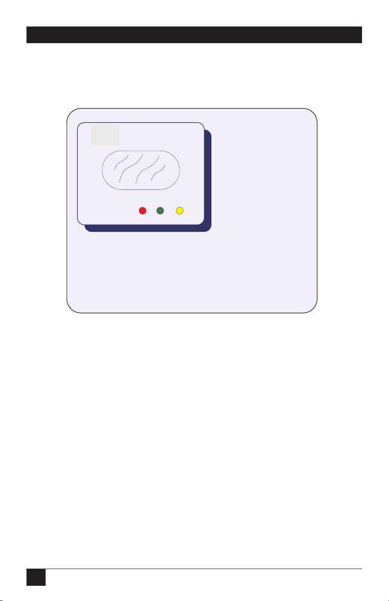
3.6 System Startup
Follow the steps listed in Figure 3-7 to start up the system.
Figure 3-7. Voice Pro top panel.
NOTES
Do not operate the unit during startup.
System startup can take anywhere from 1 to 3 minutes.
If the unit fails during startup, press the Reset button (located on the
rear of the Voice Pro) to reboot the system.
If power is disconnected from the Voice Pro, the FULL light will flash
every 4 seconds until battery power is exhausted, or power is restored
to the unit.
Voice Pro Top Panel
Voice Logic
Voice Pro
PWR In Use Full
1.
When power is supplied to the unit, all lights on the unit will
blink.
2.
The PWR light (red) remains on.
3.
The FULL light (yellow) will blink intermittently while the system
is in testing mode.
4.
Once initialized, the FULL light will go out and Station 10 will
ring 6 times indicating the system is ready for use.
Page 28
27
CHAPTER 3: Installation
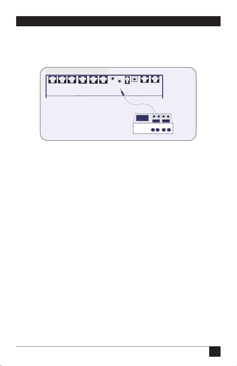
3.7 Installing an External Music Source
Follow the steps listed in Figure 3-8 to install an external music source.
Figure 3-8. Installing an external music source.
NOTE
Output requirement of the music source is no more than 0.7 V, which is
the standard output for headphone jacks.
3.8 Battery Backup
Included with each unit is a 6-VDC battery (located inside the Voice Pro). The
battery provides 6 to 10 hours of backup for memory, system programming, and
messages if the AC power fails. The Voice Pro cannot answer calls when powered
by the battery.
To maintain system integrity, install an uninterruptible power source (UPS).
Voice Pro 2 x 6 Rear Panel
Voice Pro-206 Series Rear Panel
Reset
Music
Pwr
Ext12
Ext11 Ext10
Ext13
Ext14Ext15
Voice Pro
1.
Plug the 3.5 mm. mono phono plug
into the Music jack on the rear panel.
2.
Plug the music source into an outlet,
other than the outlet dedicated to the VP
unit.
RS232
Line 2 Line 1
911224
Page 29
28
VOICE PRO
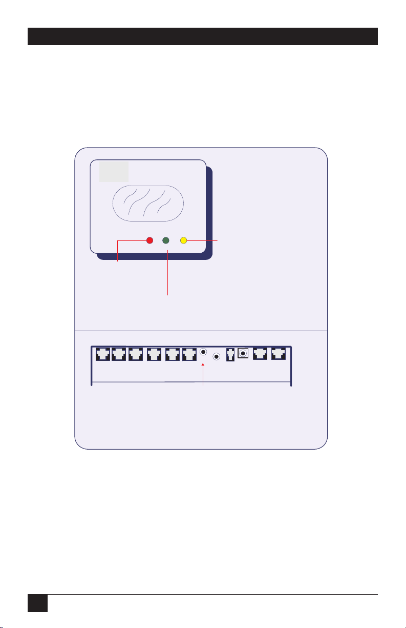
3.9 Voice Pro Indicators and Buttons
3.9.1 TOPP
ANELINDICATORS
The top section of Figure 3-9 describes the Voice Pro’s indicators, located on the
top panel.
Figure 3-9. Voice Pro top panel.
3.9.2 H
ARDWARERESETBUTTON
The bottom section of Figure 3-9 describes the functions of the hardware reset
button.
Voice Pro Top Panel Functions
Voice Logic
Remains lit when the memory
in the VP unit is full.
Blinks during self-test mode
when the unit is first turned on.
Voice Pro
PWR In Use Full
Lights up when
power is On.
Dimmed when
power if Off.
Flashes when a telephone or
other device connected to the
unit is in use.
Rear of Voice Pro Unit: Hardware Reset Button Function
Ext13
Ext14Ext15
Voice Pro
Reboots system processor, which:
deletes all voice mail messages and customized greetings, and
returns system program settings (including time , date and
greetings) to their default states.
Ext12
Ext11 Ext10
Reset
Hardware reset
button
Test mode lasts from 1 to 3
minutes.
Blinks rapidly when a message
is being recorded by the
system.
Blinks once every 4 seconds
when powered by the battery.
Music
Pwr
RS232
Line 2 Line 1
Page 30

29
CHAPTER 4: Programming the Voice Pro System
4. Programming the Voice Pro
System
The Voice Pro has been designed with voice prompts that make programming The
Voice Pro system quick and easy. You can program your system without using this
manual; however, we strongly recommend that you follow this programming guide
to ensure that the system is optimally programmed to comply with your needs.
4.1 Quick Reference Program Guide
Use the table below to quickly locate a program and its corresponding number.
Detailed instructions follow.
Table 4-1. Program guide
Program Number Program Name
1 System Password
2 CO Lines Installed
3 CO Line Access
4 CO Line Ring Assignment
5 Door Ring Assignment
6 Door Port Assignment
7 Fax Assignment
8 Hold Recall Timeout
9 Prime Line Select
10 Voice Message Length
11 Greeting Length
12 Night Mode Time Set
13 Invalid entry
14 Ring No Answer Timeout
15 Invalid entry
16 Call Forwarding
17 Remote Call Screen
18 Extension Call Screen
19 Time Set
20 Date Set
21 Record Main Greeting
CO=Central Office
Page 31

30
VOICE PRO
Table 4-1 (continued). Program guide
Program Number Program Name
22 Day Greeting Assignment
23 Night Greeting Assignment
24 Weekend Greeting
25 Record System Greetings
26 Reset Mailbox Password
27 Enable/Disable Auto-Attendant Mode
28 Invalid entry
29 Message-Waiting Light
30 Rings to Auto-Attendant
31 Assign Fax CO Line
32 Record Call-Screening Greeting
33 Weekend Time Set
34 Invalid entry
35 Outstanding Messages
36 Invalid entry
37 Call Forwarding Method
38 Invalid entry
39 Rotary Dial Support
40 CO Hook Flash Time
41 Volume Adjustment
42 Toll Restriction Stations
43 Restriction and Exception Numbers
44 Dialed Digit(s) Assignment
50 Monitor System Settings
91 Hardware Version
92 Software Version
99 System Reset
** Exit Programming
CO=Central Office
4.2 Quick Start: Program Your Voice Pro System
You can program your Voice Pro system from any telephone connected to the
Voice Pro. You can also program the Voice Pro system from a remote touch-tone
telephone.
The following program numbers are in the recommended programming order.
Program all of the following first, and then proceed to program other features that
you want to use with your system.
Page 32

31
CHAPTER 4: Programming the Voice Pro System
S
TEP
1: A
CCESS PROGRAM MODE FROM A CONNECTED STATION
1. Pick up the corded handset and listen for a dial tone.
2. Press #.
3. When prompted for the password, enter the default password 1 2 3 4 and
press #.
4. The system will verify the correct password.
NOTE
After three incorrect password attempts, you will be rejected from the
system.
S
TEP
2: I
DENTIFY INSTALLED TELEPHONE COMPANY LINES
1. When prompted for the program number, press 2.
2. Press #.
3. Enter the installed line numbers:
a. If one line is installed, press 1.
b. If two lines are installed, press 1 2.
c. If three lines are installed, press 1 2 3.
d. If four lines are installed, press 1 2 3 4.
4. Press #.
S
TEP
3: S
ET THE CLOCK
1. Remain in programming mode, and when prompted for the program
number, enter 19.
2. Press #.
3. Enter the hour (valid entries are 1 – 12) and press #.
4. Enter minutes (valid entries are 00 – 59) and press #.
5. Press 1 for AM or 2 for PM and press #. (Default is 12:00 PM)
For example, to set the time to 3:04 PM, dial 3#04#2#. (3 is the hour, 04 is minutes,
and 2 is PM.)
Page 33

32
VOICE PRO
S
TEP
4: S
ET THE DATE
Sets the current month, day, year, and day of the week.
1. Remain in programming mode, and when prompted for the program
number, enter 20.
2. Press #.
3. Enter the month (valid entries are 1 – 12) and press #. For example, press 3
for March or 9 for September.
4. Enter the day (valid entries are 1 – 31) and press #.
5. Enter the year (for example, 00 for 2000) and press #.
6. Enter the day of the week and press #. Use the following numbers:
1 = Monday
2 = Tuesday
3 = Wednesday
4 = Thursday
5 = Friday
6 = Saturday
7 = Sunday
The default is Thursday, January 1, 1998.
For example, to set the date to Wednesday, July 29, 2000, dial 7#29#00#3#. (7 is the
month, 29 is the day, 00 is the year, and 3 is Wednesday.)
S
TEP
5: R
ECORD MAIN GREETING
M
Records the greeting that is played when someone calls (also know as autoattendant). This is Greeting #1.
1. Remain in programming mode, and when prompted for the program number,
enter 21.
2. Press #.
3. After the tone, record your greeting.
4. When finished recording, press #.
Default: System greeting for daytime calls, normally used during business hours.
M
indicates that the program can be monitored using
Program 50 (50#). See Program 50 for details.
Page 34

33
CHAPTER 4: Programming the Voice Pro System
NOTES
You may exit programming mode at any time by dialing * *. When you
hear “Good-bye,” you have exited programming mode.
M
indicates that the program can be monitored using Program 50 (50#).
See Program 50 for details.
4.3 Program the Voice Pro from a Remote Touch-Tone Telephone
1. Enable auto-attendant. (The Voice Pro defaults to auto-attendant upon
power-up.)
2. Call in to the Voice Pro on any telephone line.
3. When auto-attendant answers, press #.
4. Follow the voice prompts to program your system.
4.4 Voice Pro System Program Guide
Voice Pro comes with a host of advanced features that you can program easily. The
following programs are set up while in program mode and can be done from a
connected station or remotely with a touch-tone telephone. Pick and choose from
the programs listed in this section to customize your system for your own special
needs.
NOTE
You can add or change your program settings any time you like.
If you exited programming mode in the previous section, you must return to
program mode; otherwise, proceed to select from the programs outlined in this
section.
NOTE
While in programming mode, if you do not make an entry within one
minute after the prompt, the system will hang up. Valid entries made
before that point are retained in the system.
A
CCESS PROGRAM MODE FROM A CONNECTED STATION
1. Pick up the corded handset.
2. Press #.
3. When prompted for the password, enter the default password 1 2 3 4 and
press #.
Page 35

34
VOICE PRO
The system will verify the correct password.
NOTE
After three incorrect password attempts, you will be rejected from the
system.
P
ROGRAM
1: A
SSIGN A SYSTEM PASSWORD
1. While in programming mode, and when prompted for the program number,
enter 1.
2. Press #.
3. When prompted for a new password, enter a 4-digit password and press #.
4. When asked to re-enter the password, enter it again and press #. (The default
is 1234.)
IMPORTANT
Remember your password. If you forget it, you must either use the
hardware reset button, which returns system program settings to their
default states, or call Black Box Technical Support at 724-746-5500 to
reset the password for you.
P
ROGRAM
2: I
DENTIFY INSTALLED TELEPHONE COMPANY LINES
M
1. While in programming mode and prompted for the program number, press
2.
2. Press #.
3. Enter the installed line numbers:
a. If one line is installed, press 1.
b. If two lines are installed, press 1 2.
c. If three lines are installed, press 1 2 3.
d. If four lines are installed, press 1 2 3 4.
4. Press #.
M
indicates that the program can be monitored using
Program 50 (50#). See Program 50 for details.
Page 36

35
CHAPTER 4: Programming the Voice Pro System
P
ROGRAM
3: A
SSIGN STATIONS TO TELEPHONE LINES
M
This program determines which extensions may access which telephone lines.
1. While in programming mode, and when prompted for the program number,
enter 3.
2. Press #.
3. When prompted for a line number, press 1 (for Line 1), and then press #.
4. When prompted for the corresponding extension number, enter extension
numbers in succession and then press #. For example, if extensions 10 and 11
are to be assigned to Line 1, press 1011#.
5. Repeat steps 3 and 4 for Lines 2 through 4. (Default: All incoming telephone
lines are accessible from all connected stations.)
P
ROGRAM
4: S
ELECT RINGING ASSIGNMENT FOR STATIONS
M
This program determines the extensions and the incoming lines they will ring in
on. The system will override this program when the auto-attendant program (#30)
is set to 0 ring.
1. While in programming mode, and when prompted for the program number,
enter 4.
2. Press #.
3. When prompted for a line number, press 1 (for Line 1), and then press #.
4. When prompted for the corresponding extension number, enter extension
numbers in succession and then press #. For example, if Line 1 is to ring on
both extensions 10 and 11, press 1011#.
5. Repeat steps 3 and 4 for Lines 2 through 4.
Default: Line 1 rings on station 10, Line 2 on station 11, Line 3 on station 12, and
line 4 on station 13.
P
ROGRAM
5: A
SSIGN STATION TO RING FOR DOOR OPERATION
M
1. While in programming mode, and when prompted for the program number,
enter 5.
M
indicates that the program can be monitored using
Program 50 (50#). See Program 50 for details.
Page 37

36
VOICE PRO
2. Press #.
3. When prompted for a line number, press 1 (for Line 1), and then press #.
4. When prompted for the extension number, enter the number of the
extension that the door is to ring on, and then press #. If you want it to ring in
succession on more than one extension, enter the numbers of the extensions
followed by #.
5. Repeat steps 3 and 4 for Lines 2 through 4.
Default: Rings stations 10–15 (FX700A), 10–17 (FX701A), and 10–21 (FX702A)
sequentially.
NOTE
We recommend that you have your door chime box installed by a
professional telecommunications vendor.
P
ROGRAM
6: A
SSIGN DOOR PORT
M
1. While in programming mode, and when prompted for the program number,
enter 6.
2. Press #.
3. When prompted for an extension number to assign as a door port, enter the
number, and then press #.
Default: None
NOTE
Any extension can be assigned as a door port, except for extension 10.
P
ROGRAM
7: A
SSIGN FAX STATION
M
1. While in programming mode, and when prompted for the program number,
enter 7.
2. Press #.
3. When prompted for an extension number to assign as a fax machine, enter
the number, and then press #.
Default: None
M
indicates that the program can be monitored using
Program 50 (50#). See Program 50 for details.
Page 38

37
CHAPTER 4: Programming the Voice Pro System
NOTE
All incoming faxes will be automatically switched to the assigned
station. Refer to Program 31 for additional setup information.
P
ROGRAM
8: S
ET TIMER FOR HOLD RECALL AND PARK ORBIT
M
This program sets a recall timer in seconds. Calls placed on hold or in a park orbit
will ring back to the station that initiated the hold when the timer expires.
1. While in programming mode, and when prompted for the program number,
enter 8.
2. Press #.
3. When prompted to set the timer, enter the number in seconds, and then
press #. For example, if you want the station to ring back in 30 seconds, enter
30#.
Default: 180 seconds.
P
ROGRAM
9: A
SSIGN PRIME LINES TO STATIONS
M
A prime line is the line that you want the extension to dial out on first. If in use,
then it will dial out on the next available line. A busy tone indicates all lines are in
use.
1. While in programming mode, and when prompted for the program number,
enter 9.
2. Press #.
3. When prompted for the Line number, press 1 (for Line 1), and then press #.
4. Next assign the stations that will be automatically selected by the system. Enter
the station number(s) and then press #. For example, if Stations 10 and 11
are to use Line 1 for the outgoing line, press 1011#.
Default: Station 10 on Line 1, Station 11 on Line 2, Station 12 on Line 3, and
Station 13 on Line 4.
M
indicates that the program can be monitored using
Program 50 (50#). See Program 50 for details.
Page 39

38
VOICE PRO
P
ROGRAM
10: S
ET THE VOICE MESSAGE LENGTH
M
1. While in programming mode, and when prompted for the program number,
enter 10.
2. Press #.
3. When prompted to set the voice message length, enter the number in
seconds, and then press #. For example, if you want to allow a caller to leave a
message for as long as 5 minutes, enter 300# (time in seconds). The time
entered is the allowable recording time. (Default: 120 seconds.)
NOTE
The maximum allowable length is 9999 seconds; however, we
recommend allowing 300 seconds or less.
P
ROGRAM
11: S
ET THE GREETING LENGTH
M
The greeting length allows you to set the amount of time a system user has to
record a greeting.
1. While in programming mode, and when prompted for the program number,
enter 11.
2. Press #.
3. When prompted to set the greeting length, enter the number in seconds, and
then press #. For example, if you want to allow a greeting length to be
recorded for no more than 1 minute, enter 60# (time in seconds).
(Default: 120 seconds.)
NOTE
The maximum allowable length is 9999 seconds; however, we
recommend allowing 300 seconds or less.
P
ROGRAM
12: S
ET TIME PERIOD FOR NIGHT MODE
M
When night mode is enabled, auto-attendant automatically answers all lines.
1. While in programming mode, and when prompted for the program number,
enter 12.
2. Press #.
3. Enter the hour night mode is to start (valid entries are 1–12) and then press
#.
M
indicates that the program can be monitored using
Program 50 (50#). See Program 50 for details.
Page 40

39
CHAPTER 4: Programming the Voice Pro System
4. Enter the minute (valid entries are 00–59), and then press #.
5. Press 1 for AM or 2 for PM, and then press #.
6. Enter the hour night mode is to end (valid entries are 1–12), and then press
#.
7. Enter the minute (valid entries are 00–59), and then press #.
8. Press 1 for AM or 2 for PM, and then press #.
Default: Starts 3:01 AM; Stops 3:02 AM and contains Greeting 1.
Example: If you want to start night mode at 1:10 AM and stop at 6:00 PM, enter
1#10#1#6#0#2#.
IMPORTANT
Night mode cannot be disabled. Instead, set night mode to start and end
when there is minimal telephone traffic.
P
ROGRAM
13: M
USIC ON HOLD
Default: Permanently enabled. This entry is invalid.
P
ROGRAM
14: S
ET TIME-OUT FOR“RING NO ANSWER
”
M
This program allows you to set the number of rings a station will ring before it is
automatically transferred to a voice mailbox.
1. While in programming mode, and when prompted for the program number,
enter 14.
2. Press #.
3. When prompted to set the number of rings before a call is diverted to a voice
mailbox when not answered, enter the number, and then press #.
(Default: 6 rings.)
P
ROGRAM
15: A
SSIGN GREETINGS TO TELEPHONE COMPANY LINES
M
Use this program if you want to have a separate greeting for an incoming line. (For
example, two different companies using the same Voice Pro.)
1. While in programming mode, and when prompted for the program number,
enter 15.
2. Press #.
M
indicates that the program can be monitored using
Program 50 (50#). See Program 50 for details.
Page 41

40
VOICE PRO
3. When prompted to specify the greeting, enter the greeting number (0–99)
and then press #.
4. When prompted to specify the incoming lines that the greeting is to answer,
enter the line numbers, and then press #. (Default: Greeting 1 is assigned to
all incoming lines.)
For example, if Greeting 2 is to be answered on Lines 2 and 3, enter 2#23#.
NOTE
Greetings 0–99 are assigned using program numbers 21 – 24. Greeting 0
is one of the first features programmed in the Quick Start section, and is
the default greeting to be played in all modes.
P
ROGRAM
16: A
SSIGN CALL FORWARDING
M
You can forward an extension to another extension, to your mailbox, or to a
remote telephone number.
1. While in programming mode, and when prompted for the program number,
enter 16.
2. Press #.
3. When prompted, enter the extension number to be forwarded, and then
press #.
4. Enter the number to forward calls to, then press #.
5. Press 1 for all calls or 2 for “ring no answer” calls, and then press #.
Default: No call forwarding programmed.
Example: Dial 17# to forward calls to station 17. Dial 317# to forward calls to voice
mailbox 317. Dial an outside phone number (up to 11 digits) to forward calls to an
outside number.
NOTE
You can enable or disable this feature without entering system
programming. See Section 5.13, “Call Forwarding,” for full details.
P
ROGRAM
17: P
ROGRAM PHONE TO SCREEN CALLS REMOTELY
M
You can use this program to ring your remote phone and have an incoming call
announced. See Section 5.10.
M
indicates that the program can be monitored using 50#.
See Program 50 for details.
Page 42

41
CHAPTER 4: Programming the Voice Pro System
1. While in programming mode, and when prompted for the program number,
enter 17.
2. Press #.
3. When prompted enter the station number to be screened. Press #.
4. Enter the outside number to forward calls to, and then press #.
Default: No remote screening.
NOTE
You can enable or disable this feature without entering system
programming.
P
ROGRAM
18: P
ROGRAM PHONE TO SCREEN CALLS LOCALLY
M
You can use this program to ring your station and have an incoming call
announced. See Section 5.10.
1. While in programming mode, and when prompted for the program number,
enter 18.
2. Press #.
3. When prompted, enter the station number to be screened. Press #.
Default: No local screening.
NOTE
You can enable or disable this feature without entering system
programming.
P
ROGRAM
19: S
ET THE CLOCK
1. Remain in programming mode, and when prompted for the program
number, enter 19.
2. Press #.
3. Enter the hour (valid entries are 1–12) and press #.
4. Enter minutes (valid entries are 00–59) and press #.
5. Press 1 for AM or 2 for PM and press #.
Default: 12:00 PM
M
indicates that the program can be monitored using 50#.
See Program 50 for details.
Page 43

42
VOICE PRO
For example, to set the time to 3:04 PM, dial 3#04#2#. (3 is the hour, 04 is the
minutes, 2 is PM).
P
ROGRAM
20: S
ET THE DATE
Sets the current month, day, year, and day of the week.
1. Remain in programming mode, and when prompted for the program
number, enter 20.
2. Press #.
3. Enter the month (valid entries are 1–12), and press #. For example, press 3
for March or 9 for September .
4. Enter the day (valid entries are 1–31) and press #.
5. Enter the year and press #. For example, press 00 for 2000.
6. Enter the day of the week and press #. Use the following numbers:
1 = Monday
2 = Tuesday
3 = Wednesday
4 = Thursday
5 = Friday
6 = Saturday
7 = Sunday
Default: Thursday, January 1, 1998.
For example, to set the date to Wednesday, July 29, 2000, dial 7#29#00#3#. (7 is the
month, 29 is the day, 00 is the year, and 3 is the day of the week.)
P
ROGRAM
21: R
ECORD MAIN GREETING
M
Use this program to record the main greeting (Greeting 0).
1. While in programming mode, and when prompted for the program number,
enter 21
2. Press #.
3. When prompted, begin recording the main greeting after the tone.
4. Press # to save your recording.
M
indicates that the program can be monitored using 50#.
See Program 50 for details.
Page 44

43
CHAPTER 4: Programming the Voice Pro System
Default: System greeting for daytime calls, that is, normally used during business
hours.
P
ROGRAM
22: A
SSIGN GREETINGS TO LINES FOR DAY MODE
M
Use this program if you want to have a separate greeting for incoming lines in the
day mode of operation (for example, if two different companies are using the
Voice Pro).
1. While in programming mode, and when prompted for the program number,
enter 22.
2. Press #.
3. When prompted to enter the greeting number, enter the greeting number
(1–99), and then press #.
4. When prompted to enter the line number, enter the line or lines to play the
selected greeting. For example, enter 1 2 for both lines 1 and 2.
5. Press #.
Example results: Line 1 and 2 will play greeting number 4 in day mode.
Default: Greeting 0 is assigned to all lines for day, night, and weekend mode of
operation.
NOTE
Use Program 25 to record greetings to be assigned on a per-line basis,
or if you are using different greetings for day, night, or weekend mode.
Use Program 30 to set the number of rings to the assigned telephones
before the day greeting is played to the incoming caller. A setting of 0
rings will result in the auto-attendant answering immediately in day
mode of operation. Use Program 4 to assign which extensions will ring
before auto-attendant answers the call. The number of rings before
auto-attendant (Program 30) only applies to day mode of operation.
P
ROGRAM
23: A
SSIGN GREETINGS TO LINES FOR NIGHT MODE
M
Use this program if you want to have a separate greeting for incoming lines in the
night mode of operation. For example, if two different companies are using the
Voice Pro or if you want a greeting different than the day greeting to be played at
night.
M
indicates that the program can be monitored using 50#.
See Program 50 for details.
Page 45

44
VOICE PRO
1. While in programming mode, and when prompted for the program number,
enter 23.
2. Press #.
3. When prompted to specify the greeting, enter the greeting number (1–99)
and then press #.
4. When prompted to enter the line number, enter the line or lines to play the
selected greeting. Example: “1 2” (for both lines 1 and 2).
5. Press #.
Example results: Line 1 and 2 will play Greeting 5 in night mode.
Default: Greeting 0 is assigned to all lines for day, night, and weekend mode of
operation.
NOTE
Night mode of operation overrides day mode. When the system is in
night mode, the auto-attendant answers immediately and plays the
specified night greeting assigned. Use Program 25 to record greetings
to be assigned. Greetings may be assigned on a per-line basis, and on a
per-mode-of-operation basis (day, night, or weekend mode).
P
ROGRAM
24: A
SSIGN GREETINGS TO LINES FOR WEEKEND MODE
M
Use this program if you want to have a separate greeting for incoming lines in the
weekend mode of operation. For example, two different companies using the
Voice Pro, or if you want a greeting different than the day greeting to be played
during the weekend mode.
1. While in programming mode, and when prompted for the program number,
enter 24.
2. Press #.
3. When prompted to specify the greeting, enter the greeting number (1–99)
and then press #.
4. When prompted to enter the line number, enter the line of lines to play the
selected greeting. Example: “3 4” (for both lines 3 and 4).
5. Press #.
Example results: Line 3 and 4 will play greeting number 6 in weekend mode.
Default: Greeting 0 is assigned to all lines for day, night, and weekend mode of
operation.
M
indicates that the program can be monitored using 50#.
See Program 50 for details.
Page 46

45
CHAPTER 4: Programming the Voice Pro System
NOTE
Weekend mode of operation overrides day and night mode. When the
system is in weekend mode, the auto-attendant answers immediately
and plays the specified weekend greeting assigned. Use Program 25 to
record greetings to be assigned. Greetings may be assigned on a perline basis, and on a per-mode-of-operation basis (day, night, or weekend
mode).
P
ROGRAM
25: R
ECORD SYSTEM GREETINGS
M
This program is used to record all system greetings with the exception of the main
system greeting, which can only be recorded using Program 21 (Greeting 0).
1. While in programming mode, and when prompted for the program number,
enter 25.
2. Press #.
3. When prompted, enter the greeting number (1–99) and press #.
4. Begin recording your new greeting after the tone.
5. When finished recording, press #.
Example results: Greeting number 1 has now been recorded.
Default: All greetings play Greeting 0 until recorded differently.
P
ROGRAM
26: R
ESET MAILBOX PASSWORD
M
1. While in programming mode, and when prompted for the program number,
enter 26.
2. Press #.
3. When prompted, dial the mailbox number. Press #.
Default: All extension mailbox passwords are 4321. Announce only mailboxes are
**99.
NOTE
Mailbox numbers are the same as the extension. The mailboxes may be
accessed directly from the main greeting by dialing 3 plus the extension
number. The announce-only mailboxes are 316-385 (FX700A).
P
ROGRAM
27: E
NABLE/DISABLE AUTO-ATTENDANT
M
1. While in programming mode, and when prompted for the program number,
enter 27.
M
indicates that the program can be monitored using 50#.
See Program 50 for details.
Page 47

46
VOICE PRO
2. Press #.
3. Press 1 to enable auto-attendant or press 2 to disable feature, and then press
#.
Default: Auto-attendant is automatically enabled.
P
ROGRAM
28: R
ECORD DIRECTORY NAMES
M
1. While in programming mode, and when prompted for the program number,
enter 28.
2. Press #.
3. When prompted, record the directory, then press #.
Example: Record the directory by stating the extension number and/or voice
mailbox number and name of the employee for example, “Dial 10 to reach Johnny
Appleseed; dial 11 to reach Little Jack Horner.”.
NOTE
Incoming callers must dial 9 during the greeting to access the directory.
HELPFUL HINT
Write out your directory listing before recording.
P
ROGRAM
29: M
ESSAGE-WAITING LIGHT
M
The message-waiting light, when disabled, will give the extension user a stutter
tone before giving dial tone if there are new messages in the user’s mailbox. This is
especially useful if the extension in question does not have a message-waiting light
for this feature to operate. Please note that telephone sets must be equipped with a
90-volt neon message-waiting light for this feature to operate.
1. While in programming mode, and when prompted for the program number,
enter 29.
2. Press #.
3. When prompted, consecutively dial station numbers that are to have a
message-waiting light, and then press #. For example, for stations 10, 11, and
12 to light the message-waiting light press 101112#. Or dial 99 for all
extensions, and then press #.
M
indicates that the program can be monitored using 50#.
See Program 50 for details.
Page 48

47
CHAPTER 4: Programming the Voice Pro System
4. If there are no extensions that have a message-waiting light, dial # when
prompted to enter the extension number and all message-waiting lights will
be disabled.
Default: All stations have the message-waiting light enabled.
P
ROGRAM
30: S
ETS NUMBER OF RINGS BEFORE CALL IS FORWARDED TO AUTO-ATTENDANT
M
1. While in programming mode, and when prompted for the program number,
enter 30.
2. Press #.
3. When prompted, press 1 (for Line 1), and then press #.
4. Enter the number of rings before the call is transferred to auto-attendant
(0-99), and then press #.
5. Repeat steps 3 and 4 to program the remaining line numbers.
Default: 3 rings for each line.
NOTE
If more than one line rings to a station, a busy call will automatically be
answered by auto-attendant.
P
ROGRAM
31: A
SSIGN INCOMING LINE TO FAX MACHINE
M
When fax switching is enabled on an incoming line, it is automatically answered by
auto-attendant. This ensures that the fax tone will be detected and properly
switched over to the fax machine.
1. While in programming mode, and when prompted for the program number,
enter 31.
2. Press #.
3. When prompted, enter the line number that will receive fax transmissions,
and then press #.
4. At the prompt, press 1 to enable or press 2 to disable, and then press #.
5. For multiple fax lines, repeat steps 3 and 4.
Default: None
M
indicates that the program can be monitored using 50#.
See Program 50 for details.
Page 49

48
VOICE PRO
NOTE
The system will listen for a fax tone for 2 to 5 seconds. If a fax tone is
detected, the call is automatically switched to the fax machine;
otherwise, the auto-attendant will answer the call. Refer to Program 7 for
additional setup information.
P
ROGRAM
32: R
ECORD CALL-SCREENING GREETING
M
1. While in programming mode, and when prompted for the program number,
enter 32.
2. Press #.
3. After the tone record your greeting.
4. When finished recording, press #.
Default: The following message plays, “Please record your name and a short
message at the tone.”
HELPFUL HINT
You may want to customize this greeting.
P
ROGRAM
33: S
ET TIME PERIOD FOR WEEKEND MODE
M
This program determines the day and time the weekend greeting will play. When
enabled, this program overrides day and night modes. Refer to Program 34 for
recording the greeting.
1. While in programming mode, and when prompted for the program number,
enter 33.
2. Press #.
3. Enter the start day and press #. Use the following numbers:
1 = Monday
2 = Tuesday
3 = Wednesday
4 = Thursday
5 = Friday
6 = Saturday
7 = Sunday
4. Enter the start hour (valid entries are 1–12) and press #.
M
indicates that the program can be monitored using 50#.
See Program 50 for details.
Page 50

49
CHAPTER 4: Programming the Voice Pro System
5. Enter the start minute (valid entries are 00–59) and press #.
6. Press 1 for AM or 2 for PM, and then press #.
7. Enter the stop day using the numbers listed in step 3.
8. Enter the stop hour (valid entries are 1–12) and press #.
9. Enter the stop minute (valid entries are 00–59) and press #.
10. Press 1 for AM or 2 for PM, then press #.
Default: Minimal Weekend Mode: Starts Saturday 3:01 AM; Stops Saturday 3:02
AM. Contains Greeting 1.
IMPORTANT
Weekend mode cannot be disabled. Instead, set weekend mode to start
and end when there is minimal telephone traffic.
P
ROGRAM
34: R
ECORD WEEKEND GREETING
M
Refer to Program 33 for additional setup information.
1. While in programming mode, and when prompted for the program number,
enter 34.
2. Press #.
3. After the tone record your greeting.
4. When finished recording, press #.
Default: System greeting.
HELPFUL HINT
You may want to customize this greeting.
P
ROGRAM
35: O
UTSTANDING MESSAGE NOTIFICATION
1. While in programming mode, and when prompted for the program number,
enter 35.
2. Press #.
Result: System will notify you which mailboxes have new/unheard messages.
M
indicates that the program can be monitored using 50#.
See Program 50 for details.
Page 51

50
VOICE PRO
P
ROGRAM
36: I
NSTALL“GREETING-ONLY” MAILBOXES
M
This program has been disabled, since all mailboxes that are not associated with a
valid extension number are set as greeting-only mailboxes. Greeting-only
mailboxes differ from normal mailboxes in that they do not allow a caller to leave a
voice-mail message. After the personal greeting of a mailbox of this type is played,
the caller is returned to the system’s main greeting if there is nothing dialed by the
caller. The key element that makes the mailbox a “greeting-only mailbox” is the
password. The password for a greeting-only mailbox starts with a “*”. The default
password for all greeting-only mailboxes is “**99”. By changing the password to any
other number, as long as it does not start with an asterisk “*”, will result in turning
the mailbox into a normal mailbox that can accept a voice-mail message. The
password for either type of mailbox must be 4 to 6 digits long, including the “*” if
it is to be a greeting-only mailbox.
Default: All mailboxes that do not have a valid extension number are assigned as
greeting-only mailboxes.
Example: The FX700A mailboxes that can receive messages are 10–15. The
FX701A mailboxes that can receive messages are 10–17. The FX702A mailboxes
that can receive messages are 10–21.
P
ROGRAM
37: S
ELECT CALL-FORWARDING METHOD FOR ALL LINES
M
1. While in programming mode, and when prompted for the program number,
enter 37.
2. Press #.
3. Select one of the following call-forwarding methods:
• Enter 0 and press # to have calls forwarded on 2 lines with supervision. Busy
or unanswered calls are forwarded to a voice mailbox.
• Enter 1 and press # to enable one line to have 3-way calling feature. Note: You
must subscribe to this service with your local phone company for this feature
to operate properly. Also, you will have to press # every 120 seconds to extend
the conversation, or * to extend the call indefinitely and eliminate any further
prompts.
• Enter 2 and press # to enable one line with transfer (free up port at end of
dial). Note: You must subscribe to transfer and disconnect (Centrex) lines
with your local phone company for this feature to operate properly. Also, toll
charges remain in effect until the transferred call is disconnected.
M
indicates that the program can be monitored using 50#.
See Program 50 for details.
Page 52

51
CHAPTER 4: Programming the Voice Pro System
• Enter 3 and press # to enable 2 lines to have blind transfer capabilities. Busy
or unanswered calls are not transferred to a voice mailbox and will ring until
answered.
Default: 0 (two lines with supervision).
NOTE
For additional information about this feature, refer to Section 5.13.
P
ROGRAM
39: R
OTARY DIAL TELEPHONE SUPPORT
M
Calls from a rotary (pulse) telephone, or in some cases from overseas, are unable
to dial any digits during the auto-attendant, since voice mail can only respond to
DTMF (Dial Tone Multi Frequency) dialed digits. This feature allows the caller to
automatically be transferred to the operator (extension 10 by default) if no DTMF
digits are received, as opposed to being disconnected after the main greeting for
no DTMF digit(s) dialed. Disconnecting the caller if there is no DTMF digit(s)
detected will prevent callers who hang up during the main greeting from ever
ringing through to the operator (extension 10), causing false ringing at the
operator station. If your telephone company does not provide positive disconnect
signal or your telephone lines are part of a building’s PBX (Public Branch
Exchange) system that is slow in sending positive disconnect, disconnecting the
caller will help you avoid tying up your telephone lines for a period of time longer
than necessary.
1. While in programming mode, and when prompted for the program number,
enter 39.
2. Press #.
3. When prompted, press 1 to enable or 2 to disable.
4. Press #.
Default: Rotary dial telephone support is enabled. Calls will transfer to the
operator if no DTMF is received.
P
ROGRAM
40: T
ELEPHONE LINE CENTRAL OFFICE
(CO)
HOOK FLASH TIME
M
CAUTION
Do not change this setting without first consulting Black Box Technical
Support at 724-746-5500.
The hook flash time(or flash time) that is sent over the CO line (flash 52) can be
changed to accommodate different countries’ flash times to better use the
M
indicates that the program can be monitored using 50#.
See Program 50 for details.
Page 53

52
VOICE PRO
telephone company or PBX provider features. Telephone company features such
as three-way calling, call waiting, and call transfer to another telephone number all
require issuing a flash on the CO line. The flash time may be adjusted from 100 ms
to 250 ms. Do not confuse this setting with the flash time needed to access Voice
Pro system features, which is the flash sent from your telephone to the Voice Pro
system.
Default: 5, which is equivalent to 500 ms.
P
ROGRAM
41: V
OLUME ADJUSTMENT
M
The volume of voice prompts, greetings, and messages may be changed to better
suit your volume preferences. The first part of this program controls the Voice Pro
recorded prompts. The second part of this program controls the playback volume
of voice-mail messages and recorded greetings. You can also increase or decrease
the volume while listening to a voice-mail message from your mailbox by pressing 7
repeatedly to decrease the playback volume, and pressing 9 repeatedly to increase
the playback volume.
1. While in programming mode, and when prompted for the program number,
enter 41.
2. Press #.
3. When prompted, enter 1 for system prompt volume level or 2 for recorded
messages volume level.
4. Enter new volume setting (15–31).
5. Press #.
6. Repeat this program from the beginning if you want to change both settings,
selecting the volume adjustment not selected the first time.
Default: The system prompt volume level is 23. The recorded greetings and
messages volume level is 21.
P
ROGRAM
42: A
SSIGN TOLL RESTRICTION EXTENSIONS
M
This program assigns entered extensions to follow toll restriction for long-distance
or toll dialing. When the extension number is entered on this program number, it
will not be allowed to dial any of the numbers set forth in Program 43. If a number
is dialed by any extensions that have been assigned to toll restriction, the outside
line will be dropped and the extension user will hear an error/busy tone. Toll
restricting an extension only affects the extension’s ability to call out on the
telephone CO line.
M
indicates that the program can be monitored using 50#.
See Program 50 for details.
Page 54

53
CHAPTER 4: Programming the Voice Pro System
1. While in programming mode, and when prompted for the program number,
enter 42.
2. Press #.
3. When prompted, enter the extension(s) to follow toll restriction. For
example, dial 10111415 for extensions 10, 11, 14, and 15.
4. Press #.
Default: No extensions are assigned to be toll restricted.
NOTE
For related programming, see Program 43 to set toll restriction and
exception numbers.
P
ROGRAM
43: T
OLL RESTRICTION AND EXCEPTION NUMBERS
M
Toll restriction numbers are the numbers to be restricted when an assigned
extension attempts to dial that particular number or numbers. For example, if (1)
was entered as the restriction number, any extension assigned to follow toll
restriction in Program 43 would not be allowed to connect. The line would be
dropped and the error/busy tone would be issued to that extension. This will still
allow the extension to dial local numbers and any combination of numbers as long
as the first digit is not a (1). The most common restriction numbers are 1 and 0.
Exceptions can override the restrictions. For example, if (1) was the restriction
number, you may want to allow the exception of 1-800 and 1-888 since they start
will a (1) but are toll-free. If 1-800 is entered as the exception, then any digits
following 1-800-(XXX-XXXX) would not follow as a restriction, so all 1-800 calls
would be allowed.
1. While in programming mode, and when prompted for the program number,
enter 43.
2. Press #.
3. When prompted, enter the numbers to be restricted, entering a # between
each number(s). Example: 1 # 0 # 411
4. Press # #.
5. When prompted, enter the exceptions to the toll restricted numbers.
Example: 1 800 # 1 888 # 1214.
6. Press ##.
M
indicates that the program can be monitored using 50#.
See Program 50 for details.
Page 55

54
VOICE PRO
Example results: In this example, restriction is set for no long distance (1) or
operator assistance (0). With the exception of 1-800 and 1-888, toll-free calls to
Dallas, Texas (1-214).
Default: No toll restrictions or exceptions assigned.
NOTE
For related programming, see Program 42 to set toll restriction and
exception numbers to extensions. If you restrict 9 from being dialed in
restriction programming, be sure to make the exception entry of 911.
P
ROGRAM
44: D
IALED DIGIT(S)ASSIGNMENT
M
Dialed digit(s) assignment is also referred to as single-digit dialing. As the Voice
Pro digits 1–99 can be programmed, we call it dialed digit(s) assignment. This
program allows you to pre-determine the assigned digits functionally. For example,
from the auto-attendant main greeting, you may want to have the caller dial (1) for
sales and (2) for customer support. Use this program to assign the action or
pressing (1) or (2). Your choices are:
a. Transfer the caller to an extension or extensions.
b. Send the caller directly to a mailbox to hear a personal greeting and then
leave a voice-mail message. Or, be returned to the main greeting after the
personal greeting, if the mailbox is a greeting-only mailbox.
c. Send the caller to another greeting to select additional options.
Write down your main greeting. The term “auto-attendant” refers to the total
process of the main greeting answering the incoming caller and the caller entering
digit(s) to be transferred to the extension(s), mailbox, or other greetings of their
choice. Auto-attendant does not have to answer the call immediately. You may
choose to have the calls ring to extension(s) before the caller is answered by autoattendant. Refer to Program 4 (CO line ringing assignment) and Program 30
(rings to auto-attendant).
1. While in programming mode, and when prompted for the program number,
enter 44.
2. Enter #.
3. When prompted to enter the menu number, enter the dialed digit(s) to be
programmed.
M
indicates that the program can be monitored using 50#.
See Program 50 for details.
Page 56

55
CHAPTER 4: Programming the Voice Pro System
4. When prompted, enter 1 for a mailbox, 2 for an extension, 3 for a greeting,
or 0 to delete the dialed digit(s) previous setting. Example: 2 (for an
extension). When prompted, enter the extension number(s). For example,
15101112 ( for extensions 15, 10, 11, and 12).
5. Press #.
Example results: If a caller dials 1 from the main greeting of the auto-attendant, or
from any greeting, the caller will be placed on hold and extensions 10, 11, 12, and
15 will begin to ring. If any one of the ringing extensions picks up, they will be
connected to the caller. If no one picks up, the caller will be transferred to
extension 15’s voice mailbox, since it’s the first extension assigned to ring.
Default: 0 is assigned to extension 10, 9 is assigned to greeting number 9, all valid
extensions numbers are assigned to transfer to their prospective extensions.
NOTE
You must re-enter Program 44 for each digit(s) to be assigned. These
assignments remain valid dialed digit(s) from any greeting (1–99). This
means that a digit(s) dialed from Greeting 1 will have the same
functionality as the same digit(s) dialed from Greeting 2.
P
ROGRAM
50: M
ONITOR SYSTEM SETTINGS
1. While in programming mode, and when prompted for the program number,
enter 50.
2. Press #.
3. Enter the program number to monitor its settings, then press #.
4. To monitor another program, press #, and then enter the next program
number plus #.
NOTE
All programs listed with an M in the Quick Start and Voice Pro system
program guide sections can be monitored. This feature enables you to
check a program’s settings before making any actual changes.
P
ROGRAM
91: H
ARDWARE VERSION NOTIFICATION
1. While in programming mode, and when prompted for the program number,
enter 91.
2. Press #.
Result: System will notify you as to the current hardware version of your Voice Pro.
Page 57

56
VOICE PRO
P
ROGRAM
92: S
OFTWARE VERSION NOTIFICATION
1. While in programming mode, and when prompted for the program number,
enter 92.
2. Press #.
Result: System will notify you as to the current software version of your Voice Pro.
P
ROGRAM
99: R
ESET SYSTEM
1. While in programming mode, and when prompted for the program number,
enter 99.
2. Press #.
3. At the prompt, press 1 to accept system reset, or press 2 to cancel, and then
press #.
Result: Programming is reset to its default values. Mailbox greetings and messages
remain intact.
E
XIT SYSTEM
Dial ** at any time to exit programming mode.
IMPORTANT
All of the programs listed with an M can have their settings monitored
by dialing 50# while in programming mode, and then the program
number. This feature enables you to check a program’s settings before
making any actual changes.
4.5 System Operating Tips
The Voice Pro system comes with several features that you can easily customize to
meet your special needs. Here are some tips on tailoring and using your Voice Pro
system.
Page 58

57
CHAPTER 4: Programming the Voice Pro System
You can customize your Voice Pro system by:
• recording up to 99 greetings to direct your callers (Program 25).
• recording a weekend greeting and enabling weekend mode (Programs 33 and
34).
• recording a night greeting and enabling night mode (Program 12).
Customized greetings should:
• let the caller know they have reached you by introducing yourself or your
company name.
• direct the caller by stating the available options. (For example, “If you know
your party’s extension, please dial it now.”)
• inform the caller of your business hours.
• For night and weekend greetings, inform the caller that you are not currently
in the office. Let the caller know when someone will be available to take their
phone call.
Station mailboxes:
• are automatically assigned to each station.
• are accessed by dialing 3 + station number (for example 315 for station 15),
from the main greeting. * + 3 + station number, from another extension on
the Voice Pro System. * 300, from your extension, for auto login.
• can each be programmed to answer with a personal greeting.
• are automatically assigned the default password, 4321.
• can receive two messages simultaneously, which greatly reduces the risk of
missing an important message.
Page 59

58
VOICE PRO
4.6 Auto Attendant Mode
When the Voice Pro system is initially installed and powered up, it will default to
auto-attendant mode and all callers are greeted by the system greeting. Once you
program your system, your callers can be greeted with one of six customized
greetings, as described below. The programmed greeting is played after a specified
number of rings or if the system is put in auto-attendant mode.
Greeting Option Program
Number
System greeting Default until a main greeting is recorded. N/A
Main greeting 1 Used during business hours. 21
Main greeting 2 Alternate for business hours. 22
Main greeting 3 Alternate for business hours. 23
Main greeting 4 Alternate for business hours. 24
Night greeting When night mode is enabled. 25
Weekend greeting When weekend mode is enabled. 34
While in auto-attendant mode, callers can:
• direct their call by dialing an extension number (10–21 for FX702A) or by
dialing a mailbox number (310-399).
• dial a voice mailbox number to leave a message.
• dial 9 to hear the office directory.
• return to the main greeting for more options.
NOTE
If the caller does not dial an extension or mailbox number, or if an
invalid number is dialed, the call will be transferred to station 10, which
is the operator station.
Typical greeting for a small business:
“Thank you for calling Mom’s Apple Pie Company. If you know your party’s
extension, please dial it now. If you would like to leave a message, please dial 310.
Your call will be returned as soon as possible.”
Page 60

59
Typical greeting for a home office:
“You have reached Home Office Inc. I am either out of the office or on another
phone call, so please dial 310 to leave a message. I will get back to you as soon as
possible. Thank you.”
4.7 Key System or PBX Operation
4.7.1 R
INGINGASSIGNMENTS
You can install your Voice Pro system ahead of an existing key system or PBX.
When doing so, it is recommended that the ringing assignments be done on a oneto-one basis. This is consistent with normal key system operations, so that ringing
assignments should be Line 1 rings in on Line key 1, Line 2 will ring in on Line key
2, and so on.
4.7.2 S
TANDARDOPERATION
Incoming calls are processed like any normal key system. When installed ahead of a
key system or PBX, outgoing calls are processed the same way. An access code is
not needed to get an outside line. Simply lift the receiver and dial a phone
number.
NOTE
For details on ringing assignments, see Section 4.4.
CHAPTER 4: Programming the Voice Pro System
Page 61

60
VOICE PRO
5. Using the Voice Pro System
This section provides you with detailed instructions for using all of the basic and
advanced features on your Voice Pro system.
You will learn about:
• Internal and external calling • Paging
• Flash key • Call forwarding
• Call waiting • Intercom calls
• Call pickup • Music on hold feature
• Conference calling • Virtual extensions
• Using the door chime box • Two-way recording
• Fax switching • Accessing your voice mailbox
• Placing calls on hold • Voice mailbox options
• Hold recall • Programming your voice mailbox
• Call screening • Caller options
• Transferring calls • Tips for using the system
5.1 To Make a Call
To make an outbound call:
1. Lift the receiver.
2. Listen for a dial tone.
3. Dial the phone number.
NOTE
The system automatically connects to an outside line when you pick up
the receiver.
Page 62

61
CHAPTER 5: Using the Voice Pro System
To make an outbound call on a specific telephone line:
1. Lift the receiver.
2. Press *.
3. Dial 8 and the line number. (For example, 81 for Line 1, 82 for Line 2, 83 for
Line 3, and 84 for Line 4.)
4. Listen for a dial tone.
5. Dial the phone number.
NOTE
This feature is often used for diagnosis or maintenance.
To make an internal call:
1. Lift the receiver.
2. Listen for a dial tone.
3. Press * for an internal dial tone.
4. Dial the number (for example 10 for Station 10 or 310 for a voice mailbox).
To make an internal call while on another call:
1. Press the Flash key to receive an internal dial tone.
2. Dial a number.
3. Press the Flash key to return to the previous call.
Page 63

62
VOICE PRO
5.2 Flash Key
The Flash key on your telephone activates most of the Voice Pro features. If your
phone does not have a Flash key, use the hook-switch instead.
Figure 5-1. Flash key.
NOTE
The interrupt range is approximately 0.15 to 0.08 second.
Press the Flash key to activate features. For phones that do not have a Flash key,
1 2
4 5
7 8
*
Flash Redial
3
6
9
#
0
depress the hook-switch for about 1/2
second and release to activate features.
1 2
4 5
7 8
*
Flash Redial
3
6
9
#
0
Page 64

63
CHAPTER 5: Using the Voice Pro System
5.3 Call Waiting
Follow the instructions in Figure 5-2 to use call waiting.
Figure 5-2. Using call waiting.
NOTE
You must subscribe to call waiting service from your local telephone
company to use this feature.
1.
While on a call, you will hear a "call-
waiting" beep.
2.
Press the Flash key.
3.
Dial 5 2.
The first caller is put on hold and you
can speak with the second caller.
1 2
4 5
7 8
*
Flash Redial
4.
Press the Flash key again to return to
the first caller.
The second caller is put on hold or
disconnected.
3
6
9
#
0
1 2
4 5
7 8
*
Flash Redial
1 2
4 5
7 8
0
*
Flash Redial
3
6
9
#
0
3
6
9
#
Page 65

64
VOICE PRO
5.4 Call Pickup
You can answer a call that is ringing at another station from an idle station, or
when you are on a call.
From an idle station:
1. Lift the receiver.
2. Dial * 5 0.
The call on the ringing station has been accessed.
From a station in use:
1. Press the Flash key.
2. Dial 5 0. You are switched to the incoming call.
3. Press the Flash key to return to your original call.
HELPFUL HINT
You can switch back and forth between the two calls using the Flash
key.
5.5 Conference Calls
The conference call feature allows you to speak with one outside party and two
inside parties, or two outside parties and one inside party.
Page 66

65
Figure 5-3. Conference call, example 1.
CHAPTER 5: Using the Voice Pro System
Conference Call A: 1 outside and 2 inside parties
1.
While on an outside call, press Flash.
2.
Dial 5 1.
You will receive an internal dial tone.
1 2
4 5
7 8
*
3
6
9
#
0
3
6
9
#
0
1 2
4 5
7 8
*
Flash Redial
3.
Dial an internal station number, for
example 14.
Flash Redial
1 2
4 5
7
*
Flash Redial
4.
Press Flash.
The inside station is included in the
conference call.
1 2
4 5
7 8
*
Flash Redial
3
6
9
8
#
0
3
6
9
#
0
Page 67

66
VOICE PRO
Figure 5-4. Conference call, example 2.
HELPFUL HINT
If there are no lines available when you dial 9 to access an outside line,
press the Flash key to return to the original party.
Conference Call B: 2 outside and 1 inside party
1.
While on an outside call, press Flash.
2.
Dial 5 1.
You will receive an internal dial tone.
1 2
4 5
7 8
*
Flash Redial
3.
Dial 9 to access an outside line.
1 2
4 5
7 8
*
Flash Redial
5.
Press Flash.
The outside number is included in the
conference call.
3
6
9
#
0
3
6
9
#
0
1 2
4 5
7 8
*
3
6
9
#
3
6
9
#
0
3
6
9
#
0
1 2
4 5
7 8
*
Flash Redial
4.
Listen for the dial tone and dial outside
number.
Flash Redial
1 2
4 5
7 8
0
*
Flash Redial
Page 68

67
CHAPTER 5: Using the Voice Pro System
5.6 Door Chime Box
You can program any station on your Voice Pro as a door station. Once installed
and programmed, the door chime can be accessed and answered like any other
station on your system.
To answer the door:
1. Lift the receiver.
2. Press *.
3. Dial the station number for the door chime.
4. Speak to the guest at the door.
At the door (Hands-free speaking):
1. Press the door chime.
2. When answered, speak with the party.
We recommend that you have a professional telecommunications vendor install
the door chime box.
Page 69

68
VOICE PRO
5.7 Fax Switching
Follow the steps described in Figure 5-5 for fax switching.
Figure 5-5. Fax switching.
NOTE
Fax switching must be programmed on the designated line. See
Programs 7 and 31 for programming instructions.
1.
Incoming faxes are automatically
switched to fax machine.
Switched to fax machine.
Incoming fax
Voice Logic
Incoming call on fax line
Call is answered by
greeting, "Hello, thank
you for calling....."
Voice Pro
PWR In Use Full
2.
Incoming calls on the fax line are
answered by greeting. Caller can dial
an extension or a mailbox number.
Fax
Page 70

69
5.8 Place a Call on Hold
Follow the instructions listed in Figure 5-6 to place a call on hold.
Figure 5-6. Place a call on hold.
5.9 Hold Recall
Calls that are placed on hold will ring back to its station after the programmed
timer expires. Valid timeout range is 1 to 999 seconds.
To reconnect to a call ringing back to a station:
Lift the receiver.
You are reconnected to the call on hold.
CHAPTER 5: Using the Voice Pro System
1.
Press the Flash key or depress the
hook-swich for about 1/2 second and
release.
The call is placed on hold.
2.
Hang up.
Note:
The call will ring back if the
programmed timer expires.
-or-
3.
To reconnect to the party on hold, lift
the receiver and press Flash.
1 2
4 5
7 8
*
Flash Redial
3
6
9
#
0
1 2
4 5
7 8
*
Flash Redial
1 2
4 5
7 8
0
*
Flash Redial
3
6
9
#
0
3
6
9
#
Page 71

70
VOICE PRO
5.10 Call Screening
You can screen your incoming telephone calls locally and remotely. All it takes is
some simple programming and you can enable or disable screening mode.
5.10.1 HOWD
OESCALLSCREENINGWORK
?
See Figure 5-7 for details.
Figure 5-7. Call screening.
“Hello, if you know your
party’s extension, please dial
it now.”
1.
Incoming call
2.
Call is answered by
greeting, and caller is
asked to dial an extension.
"Hello, you have reached Voice
Logic. If you know your party's
extension, please dial now."
5.
Screened station
rings and is answered.
The system prompt
plays followed by the
screened message.
Press # to
accept phone
call.
Voice Logic
Voice Pro
PWR In Use Full
3
1 2
6
4 5
9
7 8
0
*
#
Flash Redial
3.
Caller dials
'screened ' extension.
4.
System prompts caller
to leave their name and a
brief message.
"Please state your name
and a brief message and
then press the # key."
Press * to
transfer call to
voice mailbox.
1 2
4 5
7 8
0
*
Flash Redial
3
6
9
#
-or-
1 2
4 5
7 8
0
*
Flash Redial
3
6
9
#
Page 72

71
5.10.2 E
NABLE/DISABLECALLSCREENING(LOCAL
)
1. Lift the receiver.
2. Dial * #.
3. Dial 3 #.
4. Do one of the following:
To enable call screening, dial 1 #.
To disable call screening, dial 2 #.
5. Dial * * to exit programming.
5.10.3 E
NABLECALLSCREENING(REMOTE
)
1. Lift the receiver.
2. Dial * #.
3. Dial 2 #.
4. Dial remote number.
5. Press #.
6. Dial * * to exit programming.
5.10.4 D
ISABLECALLSCREENING(REMOTE
)
1. Lift the receiver.
2. Dial * #.
3. Dial 2 #.
4. Press #.
5. Dial * * to exit programming.
5.11 Call Transfer
You can perform three types of transfers: announced, unannounced and to a
mailbox.
CHAPTER 5: Using the Voice Pro System
Page 73

72
VOICE PRO
5.11.1 A
NNOUNCEDTRANSFER
1. While talking on an outside line, press Flash.
2. Dial a station number.
3. When the called party answers, announce the call.
4. Hang up.
5.11.2 U
NANNOUNCEDTRANSFER
1. While talking on an outside line, press Flash.
2. Dial a station number.
3. When you hear the extension ringing through, hang up.
5.11.3 T
RANSFER TO AVOICEMAILBOX
1. Lift the receiver.
2. Press Flash.
3. Dial a mailbox number.
4. Hang up.
NOTES
If you receive a busy or ring-no-answer signal, press Flash to return to
the caller.
If you are subscribed to Caller ID service from your local telephone
company, and you are transferring a call to an interoffice station: wait
for the second ring before picking up in order to transfer caller ID
information.
Page 74

73
CHAPTER 5: Using the Voice Pro System
5.12 Paging
You can page (ring) all idle stations, except the fax and door stations.
Figure 5-8. Paging.
NOTE
If you are connected to an outside line when paging, you can transfer
the call when it is picked up by another station.
5.13 Call Forwarding
You can forward your calls to another station, a mailbox, or to an off-site number.
You also have the option of forwarding all of your calls or busy/ring-no-answer
calls.
To enable/disable call forwarding (Local):
1. Lift the receiver.
2. Dial * #.
3. Dial 1 #.
1.
Lift the receiver.
2.
Press *.
3.
Press 7.
All idle stations will be paged (ring). The
first station to pick up will be connected
to the paging station.
1 2
4 5
7 8
0
*
Flash Redial
3
6
9
#
1 2
4 5
7 8
*
Flash Redial
3
6
9
#
0
Page 75

74
VOICE PRO
4. Dial:
another station number, or
a mailbox number, or
an off-site number (toll charges may apply).
5. Press #.
6. Press:
1 to forward all calls, or
2 to forward busy or ring-no-answer calls.
7. Press #.
8. Dial ** to exit programming.
To cancel call forwarding:
1. Lift the receiver.
2. Dial * #.
3. Dial 1 # #.
Page 76

75
5.14 Intercom Calls
5.14.1 P
LACING ANINTERCOMCALL
To place an intercom call, follow the steps listed in Figure 5-9.
Figure 5-9. Placing an intercom call.
5.14.2 R
ECEIVING ANINTERCOMCALL
To receive an intercom call, lift the receiver on the ringing station.
5.15 Music on Hold
The music on hold feature is automatically enabled when a music source is
connected to your Voice Pro. Calls placed on hold will be connected to the music
source.
To disable music on hold:
Disconnect the music source, or turn off the music source. Callers do not hear
music when placed on hold.
CHAPTER 5: Using the Voice Pro System
1.
Lift the receiver.
2.
Press * to receive an internal dial tone.
1 2
4 5
7 8
*
Flash Redial
4.
You are connected to the internal party.
3
6
9
#
0
3.
Dial station number.
1 2
4 5
7 8
*
Flash Redial
3
6
9
#
0
Page 77

76
VOICE PRO
5.16 Virtual Extensions
You have access to virtual extensions or parking orbits. Place calls in a parking
orbit when you want to place the call on hold and retrieve it from any station. The
available orbit numbers are 60–69.
To park and retrieve a call, follow the steps listed in Figure 5-10.
Figure 5-10. Parking and retrieving a call.
1.
While on a call, you will hear a beep.
2.
Press the Flash key.
3.
Dial an orbit number from 60-69.
You will hear two beeps as confirming
the call is parked.
1 2
4 5
7 8
*
Flash Redial
4.
Hang up.
The call is parked.
1 2
4 5
7 8
*
Flash Redial
7.
Dial the orbit number (range is 60-69).
Call is retrieved from parking orbit.
3
6
9
#
0
3
6
9
#
0
1 2
4 5
7 8
0
*
Flash Redial
5.
Go to another station and lift the
receiver.
6.
Press *.
1 2
4 5
7 8
0
*
Flash Redial
1 2
4 5
7 8
*
Flash Redial
3
6
9
#
0
3
6
9
#
3
6
9
#
Page 78

77
CHAPTER 5: Using the Voice Pro System
NOTES
If you do not receive a confirmation tone when dialing an orbit number
(step 3), press Flash to retrieve the caller, and repeat procedure making
sure to select an alternate orbit number.
A parked call will ring back to its original station if the recall timer
expires before it is picked up at another station.
5.17 Two-Way Recording
You can record a conversation with an outside caller.
To record a conversation:
1. While talking on an outside line, press Flash.
2. Press 4.
The conversation records to your voice mailbox.
To stop recording a conversation:
1. Press Flash and 4.
-or-
2. Disconnect the call.
WARNING
Recording a conversation without the caller’s knowledge may not be
lawful in your state.
Page 79

78
VOICE PRO
5.18 Access Your Voice Mailbox
You can access your voice mailbox locally or remotely. Follow the steps listed in
Figures 5-11a and 5-11b.
Figure 5-11a. Accessing your voice mailbox (local and remote).
For local access:
1.
Lift the receiver and press *.
1 2
4 5
7 8
0
*
Flash Redial
2.
Listen for internal dial tone.
3.
Dial your mailbox number.
Note:
Mailbox numbers are 3 + the station
number, e.g. 315.
1 2
4 5
7 8
0
*
Flash Redial
For remote access:
1.
From a remote location, dial the acess
number to the
3
6
9
#
4.
3
6
9
#
VP
voice mail system.
1 2
4 5
7 8
0
*
Flash Redial
2.
Listen for main greeting.
The personal greeting for the
dialed mailbox will play.
Proceed to the next page. . .
3
6
9
#
Page 80

79
CHAPTER 5: Using the Voice Pro System
Figure 5-11b. Accessing your voice mailbox (local and remote).
5.19 Voice Mailbox Options
After you have accessed your voice mailbox, you can select from a number of
available options. These options depend upon the status of your mailbox.
• Messages waiting—all options available.
• No messages waiting—options 9, *, and 0 are available.
5.
NOTE: The default password is 4321 for all
mailboxes with extensions, and *99 for all
announce-only mailboxes.
While the personal greeting is playing,
press *.
6.
At the prompt, enter your mailbox
password and then press #.
Note:
The default password is 1 plus the
mailbox number, e.g. 1315.
Result:
You will hear about. . .
1 2
4 5
7 8
*
Flash Redial
3
6
9
#
0
Number of messages waiting
Summary of available mailbox options
1 2
4 5
7 8
*
Flash Redial
3
6
9
#
0
Page 81

80
VOICE PRO
O
PTION:BEFORE ORAFTERLISTENING TO AMESSAGE
• Press 1 to play the next message.
Figure 5-12. Press 1 to play messages.
• Press 2 to delete the message.
Figure 5-13. Press 2 to delete the message.
• Press 3 to play the first saved message.
Figure 5-14. Press 3 to play the first saved message.
1 2
4 5
7 8
*
1 2
4 5
7 8
0
*
1 2
4 5
7 8
0
*
3
6
9
#
0
3
6
9
#
3
6
9
#
Page 82

81
CHAPTER 5: Using the Voice Pro System
• Press 4 to replay the message.
Figure 5-15. Press 4 to replay the message.
• Press 7 to undelete all previously deleted messages.
Figure 5-16. Press 7 to undelete all previously deleted messages.
NOTE
Once you exit your mailbox, messages can no longer be undeleted.
• Press 8 to forward a message to another mailbox.
Figure 5-17. Press 8 to forward a message to another mailbox.
1 2
4 5
7 8
3
6
9
#
0
*
1 2
4 5
7 8
3
6
9
#
0
*
1 2
4 5
7 8
3
6
9
#
0
*
Page 83

82
VOICE PRO
• Press 9 to program your voice mailbox.
Figure 5-18. Press 9 to program your voice mailbox.
• Press * to go to another mailbox.
Figure 5-19. Press * to go to another mailbox.
O
PTION:WHILELISTENING TO AMESSAGE
• Press 1 to play the current message from the beginning.
Figure 5-20. Press 1 to play the current message from the beginning.
1 2
4 5
7 8
3
6
9
#
0
*
1 2
4 5
7 8
3
6
9
#
0
*
1 2
4 5
7 8
3
6
9
#
0
*
Page 84

83
• Press 2 to delete the current message being played.
Figure 5-21. Press 2 to delete the current message being played.
• Press 3 to skip to the next message.
Figure 5-22. Press 3 to skip to the next message.
• Press 4 to rewind in five-second increments.
Figure 5-23. Press 4 to rewind in five-second increments.
• Press 5 to pause the message, then press 5 again to restart the message.
Figure 5-24. Press 5 to pause or restart the message.
CHAPTER 5: Using the Voice Pro System
1 2
4 5
7 8
3
6
9
#
0
*
1 2
4 5
7 8
3
6
9
#
0
*
1 2
4 5
7 8
3
6
9
#
0
*
1 2
4 5
7 8
3
6
9
#
0
*
Page 85

84
VOICE PRO
• Press 6 to fast forward in five-second increments.
Figure 5-25. Press 4 to fast forward in five-second increments.
• Press 7 to decrease the message volume.
Figure 5-26. Press 7 to decrease the message volume.
• Press 8 to forward the message to another mailbox.
Figure 5-27. Press 8 to forward the message to another mailbox.
• Press 9 to increase the message volume.
Figure 5-28. Press 9 to increase the message volume.
1 2
4 5
7 8
3
6
9
#
0
*
1 2
4 5
7 8
3
6
9
#
0
*
1 2
4 5
7 8
3
6
9
#
0
*
1 2
4 5
7 8
3
6
9
#
0
*
Page 86

85
NOTE
The message will automatically be saved when any option is pressed,
with the exception of pressing 2.
5.20 Program Your Voice Mailbox
When you access your voice mailbox and select option 9, you can change your
password, record your personal greeting, and program a message alert.
5.20.1 C
HANGINGYOUR
P
ASSWORD
Follow the steps listed in Figure 5-29 to change your password.
Figure 5-29. Change your password.
CHAPTER 5: Using the Voice Pro System
1.
Press 1.
1 2
4 5
7 8
*
Flash Redial
3.
At the second prompt, re-enter your
new password, and then press #.
Result:
3
6
9
#
0
You will hear your
new password.
2.
At the prompt, dial the new password
and then press #.
Note:
Password cannot exceed 4 digits.
1 2
4 5
7 8
*
Flash Redial
1 2
4 5
7 8
*
Flash Redial
3
6
9
#
0
3
6
9
#
0
Page 87

86
VOICE PRO
NOTE
To disable password security of your mailbox, press # instead of
entering a new password. This will allow full access to your mailbox by
simply pressing #.
5.20.2 R
ECORDINGYOURPERSONALGREETING
Follow the steps listed in Figure 5-30 to record your personal greeting.
Figure 5-30. Recording your personal greeting.
5.20.3 P
ROGRAMMINGMESSAGEALERT
To program message alert:
1. Press 3.
2. Press 1 for telephone/cell phone message alert, or press 2 for pager message
alert.
3. When prompted, enter the telephone/pager number for message alert. See
Figure 5-31 for examples of entering pager message alert numbers.
NOTE
A second page will be dispatched if the first page is not responded to
within 15 minutes.
1.
Press 2.
2.
At the prompt, record your personal
greeting and then press # or hangup to
stop recording.
1 2
4 5
7 8
*
Flash Redial
3
6
9
#
0
Result:
If you remain on
the line, you will hear your
greeting replayed.
3
2
1
6
5
4
9
8
7
2
*
l
ia
d
e
R
h
s
la
F
#
Page 88

87
Figure 5-31. Pager examples.
5.20.4 D
ISABLINGMESSAGEALERT
1. Press 3.
2. At the prompt, do not dial any numbers.
After 5 seconds, you will hear “Message alert is disabled.”
NOTE
The asterisk (*) inserts a 2-second delay. Continue to press * to extend
the delay time as needed.
5.21 Caller Options
When a caller phones in to your Voice Pro system, they can:
• direct dial an extension.
CHAPTER 5: Using the Voice Pro System
Standard pager example
9999999 * 99 #
Pager number
Separator
Code on pager to notify
you that a message was
left in your
Sky pager example
9999 * 9999999 * 99 #
Separator
Pager company number
Pager number
Enter
program
VP
mailbox.
Separator
Code on pager to notify
you that a message was
left in your
VP
Enter
program
mailbox.
Page 89

88
VOICE PRO
• access the phone directory.
• access a voice mailbox and leave a message.
5.21.1 D
IRECTDIALING ANEXTENSION
While the greeting is playing, dial the two-digit extension of the party the caller
wants to reach. The call is transferred to the extension. You can then program the
system to transfer unanswered calls to a voice mailbox.
5.21.2 A
CCESSING THEPHONEDIRECTORY
While the greeting is playing, press 9 to access the phone directory. A pre-recorded
directory plays for the caller.
5.21.3 A
CCESS AVOICEMAILBOX ANDLEAVE AMESSAGE
Figure 5-32 (on the next page) lists the steps needed to access a voice mailbox and
leave a message.
Page 90

89
Figure 5-32. Accessing a voice mailbox and leaving a message.
NOTE
You can access the voice-mail system to leave a message using an
interoffice phone (locally). Follow the steps listed below.
1. Lift the receiver and press *.
2. Listen for the internal dial tone and then dial the voice mailbox number.
3. While the personal greeting is playing, press 1 to leave a message.
4. Record your message and hang up.
1.
CHAPTER 5: Using the Voice Pro System
“Hello, to leave a message,
please dial the voice mailbox
number now.”
Incoming call is answered by
greeting, and caller is asked to
dial a mailbox number.
"Hello, you have reached
Voice Logic. To leave a
message, please dial the
voice mailbox number
now."
3.
At the voice prompt the caller can:
Press 1 to leave a message.
Press 2 to go to another mailbox.
Press 0 to return to the main
greeting.
4.
Caller presses 1.
1 2
4 5
7 8
*
Result:
The system presents a
summary of options for processing the
message to the caller.
2.
Caller dials mailbox number, e.g. 316.
Voice mailbox is accessed and personal
greeting is played.
5.
At the voice prompt, the caller
records a message after the tone, and
then presses # to stop recording.
3
6
9
#
0
Press 1 to listen to your message.
Press 2 to accept your message.
Press 3 to re-record your message.
Press 4 to abort your message.
Press 0 to repeat instructions.
3
1 2
6
4 5
9
3
2
1
6
5
4
9
8
7
#
2
*
e
R
l
ia
d
la
F
sh
7 8
*
#
0
Page 91

90
VOICE PRO
5.22 Additional Tips for Using the System
Try the following tips to use the system to your best advantage.
5.22.1 A
CCESSINGTELEPHONECOMPANYCUSTOMFEATURES
Many of the custom features offered by local telephone companies make use of the
* and # keys for activating a service. For example, you can call back the last phone
number that called you by dialing *6 9. To gain access to these types of features:
1. Lift the receiver.
2. Dial **and listen for the outside dial tone.
3. Dial the code for the feature, for example *6 9.
5.22.2 U
SING THESPEEDDIALFEATURE
If your telephone has a speed-dial feature, you can program speed-dial buttons to
activate Voice Pro features.
1. Lift the receiver.
2. Follow the instructions for your telephone to program a speed-dial button.
3. When instructed to dial a phone number, dial the Voice Pro code for the
feature.
Example: When instructed to dial a phone number, dial *5 0, which is the feature
code for call pickup from an idle station. When you press the speed-dial button in
the future, it will activate the “call pickup” feature.
Page 92

91
Appendix: Programming Changes
Appendix: Programming Changes
Use this chart to keep track of all programming changes.
Program Program Name Default Setting Programmed Setting
Number
1 System Password 1234
2 Lines Installed 1 2 3 4
3 Line Access All lines all ext.
4 Line Ringing Ext. 10 L-1
Assignment Ext. 11 L-2, etc.
5 Door Ringing None
Assignment
6 Door Port Assignment None
7 Fax Ext. Assignment None
8 Hold/Park Recall 180 seconds
Timeout
9 Prime Line Select Ext. 10 L-1
Ext. 11 L-2, etc.
10 Voice Message Length 120 seconds
11 Greeting Length 120 seconds
12 Night Mode Time Set 3:01 AM to
3:02 AM
14 Ring No Answer 6 Rings
Time-out
Page 93

92
VOICE PRO
Program Program Name Default Setting Programmed Setting
Number
16 Call Forwarding None
17 Remote Call Screen None
18 Extension Call None
Screening
19 Time Set 12:01 AM
20 Date Set Jan. 1
21 Record main greeting 0 - All Lines
(See Program 25 for 0 - night
instructions on 0 - day
recording greeting.) 0 - weekend
22 Day Greeting Greeting 0
Assignment
23 Night Greeting Greeting 0
Assignment
24 Weekend Greeting Greeting 0
Assignment
25 Record System Greeting 0
Greetings
26 Reset Mailbox 4 3 2 1 “*” plus the password will set
Password the mailbox as an
announce-only mailbox.
27 Enable/Disable Auto- Enabled
Attendant
Page 94

93
Appendix: Programming Changes
Program Program Name Default Setting Programmed Setting
Number
28 Record Directory Greeting 9
29 Message-Waiting All enabled
Light
30 Rings to Auto- 3 for each line
Attendant
31 Fax Line Assignment None
32 Record Call Screening Default Screen-
Greeting ing Greeting
33 Weekend Time Set Sat. 3:01 AM to
Sat. 3:02 AM
35 Outstanding Messages None
36 Greeting-Only All * *All the mailboxes except
Mailboxes extension mailboxes are set
to announce only.
37 Call Forwarding 0 = System 0 = 2 line conf. method,
Method Wide supervised transfer
1 = 3-way calling
2 = Centrex or Central Office
call transfer
3 = 2-line conf. method,
blind transfer
39 Rotary Telephone Enabled/
Support operator
Page 95

94
VOICE PRO
Program Program Name Default Setting Programmed Setting
Number
40 CO Hook Flash Time 0.5 seconds
(500 ms)
41 Volume Adjustment System Grts. 23
Recorded Grts. 21
42 Toll Restriction None
Stations
43 Restriction Numbers None
Exception Numbers None
44 Dialed Digits Assign- 0 = Operator ext. 10
ment 1 = Not assigned
Any digit(s) from 1-99 2 = Not assigned
may be assigned to an 3 = Not assigned
extension(s) (10–21), 4 = Not assigned
mailbox (10–99), or to 5 = Not assigned
play another greeting 6 = Not assigned
(0–99) 7 = Not assigned
8 = Not assigned
9 - Greeting 9
Additional Dialing
Assignments
Page 96

95
Appendix: Programming Changes
Program Program Name Default Setting Programmed Setting
Number
50 Monitor System N/A
Settings
91 Hardware Version N/A
92 Software Version N/A
99 System Reset Default System
** Exit Program Mode When finished doing
administrative programming.
Page 97

1000 Park Drive • Lawrence, PA 15055-1018 • 724-746-5500 • Fax 724-746-0746
© Copyright 2001. Black Box Corporation. All rights reserved.
 Loading...