

Page 1
CUSTOMER
SUPPORT
INFORMATION
Order toll-free in the U.S. 24 hours, 7 A.M. Monday to midnight Friday: 877-877-BBOX
FREE technical support, 24 hours a day, 7 days a week: Call 724-746-5500 or fax 724-746-0746
Mail order: Black Box Corporation, 1000 Park Drive, Lawrence, PA 15055-1018
Web site: www.blackbox.com • E-mail: info@blackbox.com
MARCH 1992
FX119A
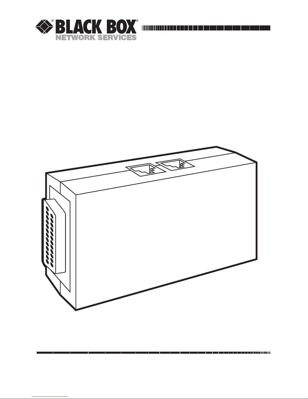
Tote-a-Fax 542
TOTE-A-FAX
DATA SPEED
FAX SPEED
CARRIER DETECT
LOW BATTERY
Page 2

1
CHAPTER 4: Operation TOTE-A-FAX 542
Tote-A-Fax 542
Installation and Operation Manual
FCC REQUIREMENTS
This equipment complies with FCC Rules Part 68. Located on the equipment is the FCC
Registration Number and Ringer Equivalence Number (REN). You must provide this
information to the telephone company if requested.
The Registration Number and REN will be inscribed on the printed circuit board on insert cards
or on a label affixed to the chassis bottom. The FCC requires these numbers be prominently
displayed on an outside surface of the device.
The REN is used to determine the number of devices you may legally connect to your
telephone line. In most areas, the sum of the REN of all devices connected to one line must not
exceed five (5.0). Contact your telephone company to determine the maximum REN for your
calling area.
The telephone company may change technical operations or procedures; these changes may
affect your equipment. You will be notified of changes in advance; this will give you the
necessary time to make arrangements to maintain uninterrupted telephone service.
If you experience trouble with this telephone equipment, contact your dealer for information
regarding service or repairs. The telephone company may ask that you disconnect this
equipment from the network until the problem has been resolved. I f your equipment continues
to disrupt the network, the telephone company may temporarily disconnect service. If this
happens, you will be informed of your right to file a complaint with the FCC.
The equipment may not be used on coin service provided by the telephone company.
Connection to party lines is subject to state tariffs.
WARNING!
This equipment generates and uses radio frequency energy. If not installed and used in
accordance with the manufacturer’s instructions, it could cause interference to radio and
television reception. It has been type tested and complies with the limits for a Class B
computing device in accordance with the specifications in Part 15 of the FCC Rules designed to
provide reasonable protection against interference in a residential installation. there is no
guarantee that interference will not occur. If this equipment causes interference to radio or
television, as determined by turning the equipment off and on, the user is encouraged to correct
the interference with the following measures:
• Reorient the receiving antenna.
• Relocate the computer with respect to the receiver.
• Plug the computer into a different outlet so the computer and receiver are on different
branch circuits.
Changes or modifications to this unit not expressly approved by the party responsible for
compliance could void the user’s authority to operate the equipment.
SHIELDED CABLES
This product has been tested and complies with FCC limits for a Class B computing device.
Using unshielded cables could cause your system to emit excess radio frequency increasing
the change of interference. To comply with FCC regulations, it is necessary to use shielded
DTE cables with your installation.
Page 3

2
TOTE-A-FAX 542
TABLE OF CONTENTS
CHAPTER PAGE
1. Specifications ......................................................................... 3
2. Introduction ............................................................................. 4
2.1 Description ......................................................................... 4
2.2 Features/Benefits ............................................................... 4
2.3 System Requirements ....................................................... 6
3. Installation ............................................................................... 7
4. Operation ................................................................................. 8
4.1 The Basics of Modem Operation ....................................... 8
4.2 Giving Commands to the Modem ...................................... 8
4.3 The AT Command Set for the Tote-A-Fax 542 ................. 10
4.4 S-Registers for the Tote-A-Fax 542 .................................. 14
4.5 Fax Command Set for the Tote-A-Fax 542 ....................... 21
4.6 Result Codes Table for the Data Modem ......................... 25
4.7 Data Compression and Error Detection for the Modem .... 26
5. Troubleshooting ................................................................... 29
Page 4

3
CHAPTER 1: Specifications
FACSIMILE MODEM
Standards — CCITT V.29/Group III, V.27 ter, V.21 sync
Speed — 9600-, 7200-, 4800-bps
Operation — Half-duplex
Interface — EIA RS-232/CCITT V.24
Certification — FCC Part 68
Transmit Level — 0 to –15 dBm
Receive Level — 0 to –43 dBm
Audio — Provided through built-in speaker
DATA MODEM
Standards — CCITT V.21, V.22, V.22 bis, Bell 103, Bell 211A
Data compression — CCITT V.42, V.42 bis, MNP Level 5
Speed — 2400-, 1200-, 300-bps
Operation — Full-duplex
Interface — EIA RS-232/CCITT V.24
Memory — Built-in non-volatile memory; EEPROM for configuration storage
GENERAL SPECIFICATIONS
System Requirements — DOS 2.1 or higher, 640K RAM
Ringer Equivalency — 0.4 B (Canadian Load Number: 41 B)
Connectors — (1) DB25 female; (2) RJ-11 telephone interface jacks
Power — 115 VAC± 10%; 60 Hz, or 9-volt battery, 200 mA
Size — 0.8"H x 2.2"W x 4"D (2 x 5.6 x 10.2 cm)
Weight — Shipping weight: 3.5 oz. (.001 kg) (not including optional Power
Supply PS 427)
1. SPECIFICATIONS
Page 5

4
TOTE-A-FAX 542
2.1 DESCRIPTION
The Tote-A-Fax 542 (FX119A) is a
compact, battery-powered, portable
9600-bps Group III fax and 2400-bps
Hayes®compatible data modem. The
data modem supports today’s most
popular and powerful data
compression and error correction
protocols: CCITT V.42, V.42 bis,
and MNP®Level 5.
The Tote-A-Fax 542 is ideal for
portable, laptop, and notebook PC
users. It is perfect for travelers who
use portable PCs and need a way to
send files from remote locations to
the office mainframe, LAN server,
PC, and/or fax machine.
The Tote-A-Fax 542 is one of our
growing line of ultra-compact
products (modems, line drivers,
muxes) that provide you with full
datacomm support and the conven-
ience of a small enclosure. Like the
Tote-A-Fax (FX112A), it is one of the
smallest fax modems in the world. It
is compatible with all DOS-based
PCs, Windows 3.0, and the Apple
Macintosh®.
With the Tote-A-Fax 542 you can
gather data while “in the field”.
Then connect the Tote-A-Fax 542 to
a telephone (in a hotel room, at
your remote office, an airport, etc.)
and to your portable PC; now you’re
ready to send files anywhere.
2.2 FEATURES/BENEFITS
2.2.1 F
AX MODEM FEATURES
• Compatible with virtually all
portable PCs and with any Group
III fax.
The Tote-A-Fax 542 is compatible with CCITT V.29 recommendations for Group III fax
transmissions. Send and receive
faxes from your
portable/laptop/notebook PC
(DOS, Windows, or Macintosh
systems) to fax machines anywhere at speeds up to 9600 bps.
• Integrated fax and data
communications software.
The integrated fax/data
communications software loads
in just a few minutes to your
portable PC. The software is easy
to use and gives you all of the
functions and options to
compile files, merge many files
into one file, and send any fax or
data file. You can even customize
a cover sheet for transmissions.
2. INTRODUCTION
Page 6

5
CHAPTER 2: Introduction
• Background Send and Receive
functions.
The Tote-A-Fax 542 sends and
receives fax files in background
mode. You continue to work
while your fax transmissions go
to their destination; you
continue to work while incoming
faxes arrive at your
laptop/portable PC. The Tote-AFax 542 doesn’t tie you down or
hold you back from your other
tasks. The end result: you send
and receive your faxes without
wasting time or being distracted
from current work in other
applications.
• Print fax files directly to a
printer.
The Tote-A-Fax 542 will print
your received fax files to your
local Epson dot matrix printer
or Hewlett-Packard LaserJet
II/III laser printer (or
compatible printers). HGA,
CGA, EGA, and VGA mono- and
color-modes are supported, too.
You can make those incoming
faxes jump through a few other
hoops, too: they can be flipped,
compressed, or expanded for
better viewing, and they can be
displayed or printed either
automatically or on demand.
• Schedule fax transmission to
save money.
The Tote-A-Fax 542 lets you
schedule your fax transmissions.
This means you can send files at
some time in the future so that
you can take advantage of lower
telephone rates. You save money
in telephone line connect
charges. Plus the Tote-A-Fax 542
provides an activity log to
monitor and manage your
incoming and outgoing fax calls;
print the activity log to add to
your business account ledger.
• Transmit a fax to a single remote
fax or to any number of fax
machines.
The Tote-A-Fax lets you do a
traditional fax transmission
(point A to point B) and it gives
you the ability to broadcast a fax
file to a group of fax machines.
This would be very helpful to
travellers who need to get the
same information out to a
number of people in different
places.
Page 7

6
TOTE-A-FAX 542
• Hayes AT Command Set
compatibility.
You can issue any of the Hayes
AT Commands to the Tote-A-Fax
542 for easy control of the
modem’s operations: you don’t
have to learn a new proprietary
communications “language” to
use this fax/data modem.
• Built-in non-volatile memory
supplied by EEPROM for
storing configuration.
• Automatic power down of the
unit for extended life of battery.
Don’t worry if you forget to turn
off the Tote-A-Fax 542—it knows
when to go to sleep to conserve
its battery power.
2.3 System Requirements
• IBM®PC/AT®or compatible
computer with at least 640K
RAM and a hard disk drive with
a minimum of 5MB of available
disk space; or
• Apple Macintosh
®
• EGA/CGA/VGA/HGA adapter
and monitor.
• Direct outside telephone line.
• Printer (optional)
2.2.2 D
ATAMODEMFEATURES
• V.42, V.42 bis, and MNP5 data
compression/error correction
protocol support.
Double or even quadruple your
effective data throughput rate
(from 2400 bps to 4800 bps,
7200 bps, or even 9600 bps). The
Tote-A-Fax 542 will
communicate with other V.42,
V.42bis, and MNP compatible
modems to get your data files to
their destination in less time—
with total accuracy. This saves
you costly telephone connect
time charges and valuable time
while you are on business.
• Compatible with five of the most
popular transmission standards:
CCITT V.21, V.22, V.22 bis,
V.23, Bell 103, and Bell 212A.
The Tote-A-Fax 542 modem can
communicate with most any
modem in the world. This wide
range of standards support is
invaluable to anyone who has to
send files to different modems
on a regular basis. You can send
your files at any of the following
three base speeds: 2400 bps,
1200 bps, 300 bps.
Page 8

7
7
CHAPTER 3: Installation
Follow these steps to connect the
Tote-A-Fax 542 to your computer:
1. Attach the 110V Power Supply
unit (PS427) to the PWR
connector on the Tote-A-Fax
542. DO NOT PLUG THE POWER
ADAPTER INTO A POWER OUTLET AT
THIS TIME. Wait until step #4 to
apply power to the modem.*
2. Connect the RS-232 connector
on the Tote-A-Fax 542 to the RS232 port on your personal
computer.
3. Connect one end of the supplied
RJ-11 telephone cable to the
LINE jack on the Tote-A-Fax
542. Connect the other end of
this cable to the telephone line
jack.
4. Plug the Power Supply unit into
a power outlet.*
Here is a listing of the indicators
(LEDs) on the front panel of the on
the Tote-A-Fax 542:
PWR............Power
AA ...............Auto Answer
SD ...............Send Data
RD ...............Receive Data
*You can also operate the Tote-AFax 542 with batteries rather than
using the Power Supply unit.
3. INSTALLATION
Page 9

8
TOTE-A-FAX 542
4.1 The Basics of Modem Operation
After you’ve connected your Tote-AFax 542 modem to your personal
computer, you need to establish a
procedure to communicate
(exchange data) with a data modem
in another location.
You now have the hardware
connected: on your end you have
the Tote-A-Fax 542 modem linked to
your PC; on the other (remote) end
there should be a modem attached
to another PC. Each modem is
attached to a telephone line.
A telephone call can be placed
between the two modems over the
telephone line. Once the modems
establish a connection, they need a
common set of parameters (rules
and limits) to exchange data bits.
This is the data communications
protocol.
4.2 Giving Commands to a Modem
Finally, you need a way to “talk” to
your modem through your
computer. You can use the:
• command code for the modem;
learning code is a difficult and
time consuming task.
• Standard AT Command Set to
issue commands to the modem.
The Standard AT Command Set is a
simplified “modem language”
supported by a majority of today’s
modems. It consists of short
groupings of keyboard characters,
followed by a carriage return or
enter key. Each character or
character group represents a
command or series of commands.
Pressing the return key initiates the
command you’ve stated to the
modem. This method of telling your
modem to do certain functions is
quick, simple, and easier to use than
command code.
The Tote-A-Fax 542’s built-in
command set is very compatible with
the Standard AT Command Set. It is
an asynchronous commu-nication
program that you can learn with
little effort. It will let you take
control of your modem through
your PC’s keyboard. The commands
are short, simple, and fast.
4.0 OPERATION
Page 10

9
CHAPTER 4: Operation
4.2.1 THEAT C
OMMAND
Each command in the Standard AT
Command Set is preceded by the
two-character sequence AT. AT is
short for “Attention!”. You control
and command the modem by first
demanding its “attention” and then
dictating your command. When you
press the return or enter key you
officially initiate the command.
Each AT Command consists of the
following elements:
1. The two-character attention
sequence AT
2. A command
3. A command parameter
4. Press the return key
NOTE: There are two exceptions to this
convention: the A/ and the +++
commands. Both commands are
discussed later in this manual.
A command is not initiated until you
press the carriage return key <CR>.
The modm ignores entries
represented as spaces (that is, if you
press the space bar on your keyboard
the modem does not acknowledge
these characters as part of the
commad).
4.2.2 AT C
OMMANDPARAMETERS
Not all commands have command
parameters associated with them. If
a parameter is missing from an AT
command statement, the value of
zero is assigned to it. Sometimes
zero is actually a valid command
parameter.
Summary
: The sequence of
characters that follow the AT
sequence constitute the core of the
command. They cause the modem
to enter a command state.
Command parameters give the
modem further details about the
command. Pressing the carriage
return key initiates the command
(that is, the modem goes to work).
If you key in AT without a command,
you are simply sending a “wakeup
call” to the modem, telling it to get
ready to listen to a command.
The modem queues commands in a
40-character command line. The
command line beginning with AT
can have several commands.
NOTE: It is not necessary to have a
separator between the commands.
Here is the command line format:
AT command <parameter>command<parameter>
<CR>
The carriage return <CR> terminates the command line. When the
modem receives the <CR> the
commands are performed in the
order in which they are sent to the
modem. If more than 40 characters
are sent to the modem an error
occurs; all commands must then be
retentered.
4.3 The AT Command Set for the
Data Modem
The following table gives the AT
commands supported by Tote-A-Fax
542 modem, including a description
of each command, its command
“range” and size. Pertinent notes
are included within the table.
Page 11

10
TOTE-A-FAX 542
COMMAND DESCRIPTION/RANGE —SIZE
A/ Execute previous command, without pressing <CR> key
AT Attention
ATA Answer immediately
ATB0 CCITT V.22 mode
ATB1 Bell 212A mode (default)
ATDP Dial using Pulse Dial
ATD Dial command
ATDT Dial using DTMF Tone Dial Default
ATDL Dial using last number, regardless of last command
Note: The following eight modifiers will dial using the previously used technique (pulse or
tone), or the
T or P command can be added after the D (Dial) command.
ATDW Wait for Dial tone for period set by S7 register
ATD@ Quiet answer: wait for 5 seconds of silence before dialing
ATD! Hookflash: commonly used in PBX systems
ATDR Reverse answer mode
ATDSn Dial stored number n=0–3
ATD/ Wait 0.125 seconds
ATD; Return to command mode after dialing
ATD, Pause for amount of time set in Register S8
ATE0 Command echo disabled
ATE1 Command mode echo enabled (default)
ATF0 No echo when connected
ATF1 Echo transmitted characters when connected (default)
ATH0 Go on hook (open relay)
ATH1 Go off hook (close relay)
Page 12

11
CHAPTER 4: Operation
COMMAND DESCRIPTION/RANGE —SIZE
ATI0 Identification Code
ATI1 Identification Code
ATI2 “OK” response if checksum verifies
ATI3 Revision number
ATL0 Lowest volume setting
ATL1 Same as ATL0
ATL2 Medium volume setting (default)
ATL3 Maximum volume setting
ATM0 Speaker always off
ATM1 Speaker on until carrier is detected (default)
ATM2 Speaker always on
ATM3 DTMF Tones are not heard, but speaker is on until carrier detected
AT0 Originate immediate or return to data mode
ATQ0 Enable result code (default)
ATQ1 Disable result code
ATSn? Provide S Register Value (n=0—27)
ATSn= Set register value (n=0—27)
ATV1 Verbose response (default). See ATV0 for response.
ATW0 Negotiation process result codes not returned (default)
ATW1 Negotiation process result codes returned
ATX0 Enable result codes 0—4
ATX1 Enable result codes 0—5
ATX2 Enable result codes 0—6
ATX3 Enable result codes 0—5, 7, and 10
ATX4 Enable result codes 0—10 (default)
ATY0 Disable long space disconnect (default)
ATY1 Enable long space disconnect
ATZ0 Software reset, restore S Register from Profile Location 0
ATZ1 Restore S Register
AT&C0 EIA carrier line always forced on (default)
AT&D0 DTR always on (default)
AT&D1 Modem goes to command mode when DTR goes Off
Page 13

12
TOTE-A-FAX 542
COMMAND DESCRIPTION/RANGE —SIZE
AT&D2 Modem goes On Hook and return to command mode when DTR
goes Off
AT&D3 Modem initializes when DTR goes OFF
AT&F Fetch S Register from EPROM for factory default
AT&G0 No guard tone (default)
AT&G1 500 Hz guard tone enabled
AT&G2 1800 Hz guard tone enabled
AT&J0 RJ-11 select (default)
AT&J1 No function
AT&L0 Switched line select (default)
AT&L1 Leased line select (not supported)
AT&M0 ASynchronouse mode (default)
AT&P0 US Make/Break Ratio for Pulse dialing (default)
AT&P1 UK Make/Break Ratio for Pulse dialing
AT&Q0 Same as AT&M0
AT&R0 Clear to Send (CTS) follows RTS (default)
AT&R1 CTS always On
AT&S0 Data Set Ready (DSR) always On (default)
AT&S1 DSR normal
AT&T0 Terminate test in progress (default)
AT&T1 Initiate local analog loopback for time set by register S18
AT&T2 Not defined
AT&T3 Initiate digital loopback for time set by register
AT&T4 Enable remote digital loopback (RDLB) response
AT&T5 Disable remote digital loopback (RDLB) response
AT&T6 Initiate RDLB
AT&T7 Initiate RDLB with Self Test
AT&T8 Initiate ALB with Self Test
AT&W0 Write S Registers into User Profile Number 0
AT&W1 Write S Registers into User Profile Number 1
AT&X0 Modem provides transmit clock
AT&X1 DTE supplies transmit clock
AT&X2 Slave clock mode (not supported)
Page 14

13
CHAPTER 4: Operation
COMMAND DESCRIPTION/RANGE —SIZE
AT&Y0 Power up recall User Profile 0
AT&V List configuration both active and stored
AT&7m=An Store telephone numbers into NVRAM (XL93C46) where:
m is the Number Location (0—3)
A is P or T (Pulse or Tone)
n is the telephone number
Page 15

14
TOTE-A-FAX 542
4.4 S-Registers for the Data Modem
4.4.1 W
HAT IS AN
S-R
EGISTER
?
A modem holds vital information
about modem configuration and
operation in internal memory
locations called Status (S-) Registers.
Each S-Register is assigned a number
from 0 to 27, and each contains 8
data bits (or, one byte of
information). In some S-Registers
each bit has a different function;
these are termed bit-mapped SRegisters. The bits are numbered
0—7, with 0 the least significant bit.
Other S-Registers use the total
number of bits (8) to represent a
single value.
One of the functions of an S-Register
is to store modem configuration
information. Thus, commands
which change or alter the
configuration operate by modifying
the corresponding S-Register.
Most S-Registers have a fixed,
predefined meaning to the modem,
and can be read or altered. Others
are read only registers; if you try to
change that particular register, the
modem responds with an error
message. Still other registers are
either destined not to be used or are
reserved for future options for the
modem. A reserved register cannot
be read or changed.
4.4.2 BIT-M
APPED
S-R
EGISTERS
Bit-mapped S-Registers contain
configuration information for more
than one option or modem
function. Each bit is mapped to a
different modem function.
Sometimes a group of bits within a
particular register are mapped to a
function.
4.4.3 D
IFFERENT
S-R
EGISTERSETS AND
T
HEIRPURPOSES
The Tote-A-Fax 542 modem uses
three different sets of S-Register
values to do its various functions and
options. You can alter (modify)
some registers but not others.
Here is a summary of the three types
of S-Reigsters:
• Active (Current) Configuration
S-Registers
These are the S-Register values
that the modem uses to operate.
When you “read from” or “write
to” an S-Register, you are
working with an active (current)
configuration S-Register.
Page 16

15
CHAPTER 4: Operation
• Stored Configuration S-Registers
Stored configuration S-Registers
are kept in nonvolatile memory;
the register values are stored in a
semiconductor random access
memory (RAM) chip that retains
the informa-tion even when the
modem loses power. So if the
modem’s batteries wear down,
the power adapter is unplugged,
or the power outlet fails, the
stored configuation S-Registers
remember their contents.
When the modem powers up it
loads the current S-Register
configuration with the stored
configuration.
Use the AT commands discussed
at the beginning of this chapter
to store your current
configuration to the stored
configuation, or to load the
current configuration with the
stored configuration.
• Factory Configuration SRegisters
These registers are factory-set
choices for the modem; they
form a “default” configuration.
These values are permanently
stored in a “read only memory”
(ROM) semiconductor chip.
Page 17

16
TOTE-A-FAX 542
This configuration can be used to reset your S-Registers with known
default values—a home-base for the modem to return to should you want
to reset your modem configuration.
4.4.4 S-R
EGISTERNUMBERS AND THEREGISTERFUNCTIONS
The table on the following pages lists all 27 S-Register numbers and includes
a description of each register’s function.
Refer to the Software User’s Manual for instuctions on how to change the
S-Registers for the Tote-A-Fax 542 modem.
S-Registers for the Data Modem
Page 18

17
CHAPTER 4: Operation
REGISTER
NUMBER REGISTER FUNCTION
S0 Number of rings to answer: default = 0 (no answer) (stored)
S1 Ring count: Stores number of rings
S2 Escape code character; default = 043 (ASCII character is + )
S3 Carriage return charactere; default = 013
S4 Line feed character; default = 043 (ASCII character is + )
S5 Back space character; default = 003
S6 Wait for dial tone; default = 002 (seconds) (minimum setting)
S7 Wait for carrier after dial; default = 030 seconds
S8 Duration for delay after comma; default = 002 (seconds)
S9 Carrier detect response time; default = 0.6 (seconds)
S10 Lost carrier to hang up delay; default = 1.4 (seconds)
S11 Touch tone duration; default = 095 (milliseconds)
S12 Escape code guard time; default = 1 (seconds)
S13 Bit mapped register
S14 Bit mapped register: stored in nonvolatile RAM (XL93C46)
Bit 0 Reserved
Bit 1 Echo
Bit 2 Result codes
Bit 3 Numeric result codes
Bit 4 Always 0
Bit 5 Tone/Pulse dialing
Bit 6 Reserved
Bit 7 Answer/Originate
S15 Reserved
S16 Test Register
Bit 0 ALB
Bit 1 Reserved
Bit 2 Local Digital Loopback
Bit 3 Remote Digital Loopback
Page 19

18
TOTE-A-FAX 542
REGISTER
NUMBER REGISTER FUNCTION
S16 Test Register (continued)
Bit 4 Initiate Remote Test
Bit 5 Initiate Remote Test with Self Test
Bit 6 Analog Loopback with Self Test
Bit 7 Reserved
S17 Reserved
S18 Test time stored in nonvolatile RAM (XL93C46);
default = 000 (seconds)
S19 Reserved
S20 Reserved
S21 Bit mapped register: stored in nonvolatile ROM (XL93C46)
READ ONLY MEMORY
Bit 0 0 = RJ11 Jack
Bit 1 Reserved
Bit 2 CTS/RTS Function
Bit 3 DTR Function
Bit 4 DTR Function
Bit 4 Bit 3 Function
0 0 DTR always true — default
0 1 DTR Off, forces command state
1 0 DTR Off, forces modem offline
1 1 Modem initializes with DTR Off (ATZ)
Bit 5 EIA carrier status
Bit 6 Guard tone select
Bit 7 Guard tone select
Bit 7 Bit 6 Function
0 0 No guard tone — default
0 1 550 Hz guard tone
1 0 1800 Hz guard tone
1 1 Reserved
Page 20

19
CHAPTER 4: Operation
REGISTER
NUMBER REGISTER FUNCTION
S22 Option bit mapped register
Bit 0 Determines speaker volume
Bit 1 Determines speaker volume
Bit 1 Bit 0 Function
0 0 Low speaker volume
0 1 Low speaker volume
1 0 Medium speaker volume — default
1 1 High speaker volume
Bit 2 Determines speaker status
Bit 3 Determines speaker status
Bit 3 Bit 2 Function
0 0 Speaker always off
0 1 On until carrier is detected — default
1 0 Speaker always on
1 1 Same as “01”, except off for dialing
Bits 4-6 Determines response messages
Bit 6 Bit 5 Bit 6 Function
000
Basic message set
100
Extended with connect 1200, connect 2400
101
Extended with “No dial tone”
110
Extended with “Busy”
111
Extended with all messages
— default
Bit 7 Determines Off Hook/On Hook (Make/Break) Ratio for
Pulse dialing
Bit 7 Ration
0 39/61 (USA and Canada); default
1 33/67 (UK and Hong Kong)
Page 21

20
TOTE-A-FAX 542
REGISTER
NUMBER REGISTER FUNCTION
S23 Option bit mapped register
Bit 0 determines whether a request from a remote modem for
RDLB is acknowledged. The Default is Enabled.
(Bit 0 Set)
Bit 1 Determines speed of transmitting and receiving data
Bit 2 Determines speed of transmitting and receiving data
Bit 1 Bit 2 Speed (bps)
0 0 300
0 1 Reserved
1 0 1200
1 1 2400
Bit 3 Undefined
Bit 4 Determines the parity for transmitting and receiving data
Bit 5 Determines the parity for transmitting and receiving data
Bit 4 Bit 5 Parity
0 0 Even — default
0 1 Space/None
1 0 Odd
1 1 Mark
Bit 6 Determines guard tone frequency
Bit 7 (Used in European applications)
Bit 7 Bit 6 Guard Tone (Hz)
0 0 Even — default
0 1 Space/None
1 0 Odd
1 1 Undefined
S24 Not used
S25 Delay to DTR (stored in nonvolatile RAM);
default = 005 (seconds)
S26 RTS to CTS delay (synchronous mode only)
Page 22

21
CHAPTER 4: Operation
REGISTER
NUMBER REGISTER FUNCTION
S27 Bit mapped register stored in nonvolatile RAM
Bit 0 Transmission mode
Bit 1 Transmission mode
Bit 1 Bit 0 Function
0 0 Asynchronous mode — default
0 1 Synchronous mode 1
1 0 Synchronous mode 2
1 1 Synchronous mode 3
Bit 2 Reserved
Bit 3 Reserved
Bit 4 Transmission mode
Bit 5 Transmission mode
Bit 5 Bit 4 Function
0 0 Internal mode clock used — default
0 1 DTE supplied clock
1 0 Slave clock mode
1 1 Same as “00”
Bit 6 CCITT or Bell handshaking standard
0 CCITT handshake
1 Bell handshake (including CCITT V.22 bis)
Bit 7 Reserved
Page 23

22
TOTE-A-FAX 542
4.5 Fax Command Set for the Fax Modem
COMMAND FACTORY DEFAULT DESCRIPTION
+FCLASS N=0 Select Service Class. +FCLASS=n command
sets the active service class.
+FCLASS=0 Return to data mode
+FCLASS=1 Fax Class 1
+FCLASS=2 Fax Class 2 (not supported)
+FCLASS=3 Fax Class 3 (not supported)
+F<command>? Report Active Configuration. +F<command>?
interrogates the modem to determine the active
configuration.
The responses are:
+FAA? 0 if auto answer is disabled
1 if auto answer is enabled
+FCLASS? 0 if in data mode
1 if in fax mode
+FF? 0 if flow control off
1 if flow control on
+F<command>=? Report Operating Capabilities.
+F<command>=? can be used to determine the
operating capabilities of the modem.
The responses are:
+FAA=? 0, 1
+FCLASS=? 0, 1
+FTM=? 24, 48, 72, 96
+FRM=? 24, 48
+FTH=? 3
+FRH=? 3
+FF=? 0, 1
+F<command>=<parameter>? interrorgates the
modem as to whether that fraction is supported.
The modem responds with OK if the parameter
Page 24

23
CHAPTER 4: Operation
COMMAND FACTORY DEFAULT DESCRIPTION
issued for the specific command is supported or
will respond with ERROR if it is not supported.
+FAA Data/Fax Auto Answer. +FAA command
configures the modem to automatically detect
whether an incoming call is from a data modem
or a fax modem. This command is valid in both
data and fax modes.
n=0 Disable data/fax auto answer mode (default).
The modem answers according to the +FCLASS
setting.
n=1 Enable data/fax auto answer mode. The
modem determines calling type and issues
DATA result code (13) if caller is a data modem
or issues FAX result code (15) if call er is a fax
modem.
+FF n=0 Enhanced Flow Control. +FF command
enables flow mode for data transfer between the
DTE and the DCE.
n=0 Disable enhanced flow control interface. In
this mode, data transfer is compatible with the
EIA-578 standard. n=1 Enable enhanced flow
control.
+FTS=n n=0 Stop Transmission & Wait. +FTS=n causes
the modem to terminate a transmission. The
transmission is terminated and the modem waits
for n 10 millisecond intervals before responding
with the OK result code. An ERROR response
code appears if this command is issued while the
modem is on-hook.
Page 25

24
TOTE-A-FAX 542
COMMAND FACTORY DEFAULT DESCRIPTION
+FRS=n n=0 Receive Silence. +FRS=n causes the modem
to report back to the DTE with an OK result code
after n 10 millisecond intervals of silence have
been detected on the line. This command is
aborted if any command character is received.
The modem discards the aborting character and
issues an OK result code. An ERROR response
code results if this command is issued while the
modem is on-hook.
+FTM=n N-48 Transmit Data. +FTM=n causes the modem to
transmit data using the modulation technique
defined below. An ERROR response code
results if this command is issued while the
modem is on-hook.
+FTM=24 V.27 ter 2400 bps
+FTM=48 V.27 ter 4800 bps
+FTM=72 V.29 7200 bps
+FTM=96 V.29 9600 bps
+FTH=n n=3 Transmit Data with HDLC Framing. +FTH=n
causes the modem to transmit data framed in
HDLC protocol using the modulation defined
below. An ERROR response code results if this
command is issued while the modem is on-hook.
+FRH=3 V.21 Channel 2 300 bps
+FRTn n=48 Receive Test Data. +FRTn causes the modem
to go off-hook and begin demodulating received
data at the specified rate.
n
Configuration/Data Rate
n=24 V.27 ter 2400bps
n=48 V.27 ter 4800 bps
Page 26

25
CHAPTER 4: Operation
COMMAND FACTORY DEFAULT DESCRIPTION
+FTTn=m n=96, m=0 Transmit Test Data. +FTTn=m causes the
modem to transmit a continous eye pattern at the
specified rate. The transmission will terminate
by a DTE abort (i.e., any character recognized at
the DTE interface).
n
Configuration/Data Rate
n=24 V.27 ter 2400bps
n=48 V.27 ter 4800 bps
n=72 V.29 7200 bps
n=96 V.29 9600 bps
m
Test Pattern
m=0 ASCII data
(20h—7fh sequential)
m=1 All zeros
m=2 All ones
m=3 Alternate 1, 0
m=4 Sliding 0 (01111)
m=5 Sliding 1 (00001)
Page 27

26
TOTE-A-FAX 542
4.6 Result Codes Table for the Data Modem
Word(s) Digit
Code Code Meaning
OK 0 Acknowledges execution of the command line.
CONNECT 1 A connection has been established at 0 to 300
bps.
RING 2 Ring detected.
NO CARRIER 3 Failure to connect or a loss of the carrier signal.
ERROR 4 This command is not recognized.
CONNECT 1200 5 A connection has been established at 1200 bps.
NO DIALTONE 6 A dial tone is not detected within the specified
time.
BUSY 7 A busy signal is detected.
NO ANSWER 8 Five seconds of silence was not detected when
the dial modifier
@
was issued.
CONNECT 2400 10 A connection has been established at 2400 bps.
Page 28

27
CHAPTER 4: Operation
The result? Your personal computer
can talk to the Tote-A-Fax 542
modem at high speeds (that is, your
PC can feed data to the modem in
large quantities) and yet your
modems can still talk to each other
at 2400 bps. And the data travels
from one computer to the other
computer without errors.
4.7.2 CCITT V.42, V.42
BIS
The same scenario applies when the
V.42 or V.42 bis standards are
applied to the data exchange
between DTE and modem. The
V.42 specifications formally
standardize and enhance the error
correction functions that make up
MNP Levels 2–4 (MNP protocols
have been, until recently, the de facto
industry standards).
CCITT V.42 is now an internationally recognized standard for error
correction. Similarly, CCITT V.42
bis is the new accepted standard for
data compression techniques; V.42
bis roughly corresponds to MNP
Level 5. One big difference is in the
amount of data compressed: V.42
bis generates about a 4:1 ratio of
data compression, while MNP Level
5 generates a 2:1 ratio of data
compression.
NOTE: The extent of compression is always
dependent on the type of file that is
being transferred.
Finally, no matter which data
compression and error correction
protocols you apply to your data
transmissions, a vital factor for the
overall success of your data transmissions will be due to the quality
of the connection made over dialup
telephone lines between your modem
and the remote modem.
4.7 Data Compression and Error
Detection for the Modem
This section explains the concepts
behind a set of data protocols (MNP
Levels 1–5) and a set of international standards (V.42/V.42 bis), both of
which involve the application of data
correction and compression
techniques.
4.7.1 MNP L
EVELS
1—5
The Microcom Networking Protocol
(MNP) doesn’t apply to data
transmission between modems; rather,
they apply to data exchanges between
a DTE and modem.
What does this mean to the user of a
modem that supports these protocols? You can send data from your
DTE (PC, data terminal, etc.) to the
modem at speeds higher than 2400
bps. The modem then implements
the MNP 1–5 protocols, which
compress the data using an encoding scheme, and checks the data for
errors, corrects the errors, and sends
the data over the phone line.
The transmission is still, for
example, 2400 bps. But the data has
been encoded and compressed
(eliminating “wasteful” data), so the
amount of data sent represents more
than the 2400 bps.
The remote modem that receives the
signal does the following: it
“rebuilds” or (decompresses) the
data, checks it for errors, corrects
the errors, and funnels the data to
the remote DTE (computer).
NOTE: Data correction/compression
techniques are applied to
asynchronous data only.
Page 29

28
TOTE-A-FAX 542
In other words, if you happen to get
a poor quality connection (and it is
totally random), you will not
quadruple your data throughput
simply because the local and remote
modems both support V.42 and V.42
bis. You will get a higher effective
data throughput working with two
modems that support V.42 and V.42
bis. But you will get a higher
effective data throughput with a
good “clear” connection, and a
correspondingly lower effective data
throughput speed with a “noisy”
connection.
4.7.3 V.42 & V.42
BIS INDETAIL
The Tote-A-Fax 542 modem
supports V.42 and V.42 bis. An
internal controller regulates data
compression. Efficient block size
adjustments help to compensate for
situations where the signal-to-noise
ratio is poor.
A V.42 bis modem combines two
error correction protocols: Link
Access Procedure–M (LAPM), and
MNP 1–4. This increases the the
possibility of an error-free transmission. Data is sent in frames with
a “start” bit and a “stop bit” on either
end of the data frame. The start and
stop bits are “stripped” from the data
being transmitted. This means only
eight (8) bits per character are sent
from the local terminal device (your
PC), rather than 10 bits per
character. This represents a 20%
gain in data throughput. However,
this gain is partially off-set by the
framing characters and Cyclic
Redunancy (CRC) data used by
MNP.
Encoded information is added to the
data frame for the receiver to
decode. It then determines if the
block was error free. That determination is made through the CRC
process. The receiver checks the
data-encoded information to:
• Indicate if the data is correct.
• Recognize and identify inperfect
data frames/
• Determine if the data has failed
CRC. If so, retransmission is
automatically spread.
The V.42 bis modem works by a
simple process. Its initial action is to
seek LAPM error correction
compatibility with the receiving
modem.
• If the compatibility exists, it
employs the LAPM error
correction protocol.
• If the V.42 bis modem cannot
find LAPM compatibility, it tries
to connect using the MNP-5
protocol.
• If it can’t establish connection
according to either protocol, it
will still connect withthe remote
modem in normal mode; error
correction is not applied.
4.7.4 S
UMMARY
The Tote-A-Fax 542 modem is a
2400 bps modem. It has the
potential to allow effective data
throughput of up to 7200 bps when
it uses MNP Level 5 data
compression, or up to 9600 bps
when it uses the V.42 bis data
compression protocol.
Page 30

29
CHAPTER 5: Troubleshooting
How do I find out if I have any COM
PORTS (communications ports) on
my computer?
First, consult your PC’s owner’s
manual. You can also run a
diagnostics program, if necessary.
I am using a “mouse” on COM
PORT 1. On which COM PORT
should I install my modem?
COM PORTS 1 and 3 share the same
IRQ (Interrupt Request Line) within
the computer. Set your modem to
either of COM PORTS 2 or 4. If you
are using a mouse on COM PORTS
2 or 4, set the modem for COM
PORTS 1 or 3. Make sure that you
disable COM PORT 1 or 3 and IRQ4
from the other serial board.
Can I use the same modem
communications software for both
an internal and external modem?
Yes. The external modem will work
off your serial adapter board.
What causes non-sensical text or
characters to appear on my screen?
How do I correct this problem?
What you see on your computer
screen is referred to as “garbage”.
There are eight common causes:
1. A conflict with IRQ with other
serial ports.
2. Initialization is not correct.
Refer to Chapters 3 and 4 of this
manual.
3. The data rate (baud or bps rate)
of your modem does not match
the rate of the host modem.
4. The parity bit is not set properly.
5. The stop bit is not set properly.
6. The modem is not set to full-
duplex.
7. If there is hissing on the
telephone line and garbage on
the screen, the telephone line is
most likely the culprit. You have
received a bad connection,
perhaps due to a weather
disturbance. Disconnect the call
and try again.
8. The modem may be defective.
5. TROUBLESHOOTING
Page 31

30
TOTE-A-FAX 542 TOTE-A-FAX 542
Run an analog loopback test to
determine whether the problem is
one of the first seven listed above, or
if it is a faulty modem. To run this
test, issue either of the following AT
commands:
AT&T1
This command will initiate a local
analog loopback test
AT&T8
This command will initiate an analog
loopback and a modem self test.
Whichever test you select, observe
the LEDs on the modem and
monitor the activity on your PC
screen.
If the loopback test is successful
without creating garbage on the
screen, then the modem is working
properly. The problem is most likely
in the configuration you have
chosen, in your PC, or in the
telephone line.
I tried to transfer a compressed data
file (.ZIP file, .ARC file, etc.) but
did not get a higher effective data
throughput with this modem. Why?
This modem has the ability to
compress data files before
transmitting the data to the
receiving modem. This enables
effective data throughput rates much
higher than the actual modem
connection data rate. If you have
the modem configured to use the
V.42 bis/MNP Level 5 data
compression protocols (which is
probably the case), then you are
transferring a data file which is
already compressed. The data
compression protocols cannot
compress the data anymore. Thus,
the data throughput is not higher.
To send and receive data files
(either fax or computer files), do I
need to have my PC turned on?
Yes.
Page 32

SEPTEMBER 1992
FX119A
ADDENDUM I
Tote-A-Fax 542
This document contains corrections to your Tote-A-Fax 542 Installation and Operation Manual (August
1992). Changes are indicated by the use of vertical black bars in the margin of each page, as shown to
the right of this statement.
1.0 SPECIFICATIONS
DATA MODEM
Standards — CCITT V.21, V.22, V.22 bis, Bell 103, Bell 212A
Data compression — CCITT V.42, V.42 bis, MNP Level 5
(software)
Speed — 2400-, 1200-, 300-bps
Operation — Full-duplex
Interface — EIA RS-232/CCITT V.24
Memory — Built-in non-volatile memory; EEPROM for
configuration storage
GENERAL SPECIFICATIONS
System Requirements — DOS 2.1 or higher, 640K RAM
Ringer Equivalency — 0.4 B (Canadian Load Number: 41 B)
Connectors — (1) DB9 female; (1) RJ-11 telephone interface
jack
Power — 115 VAC± 10%; 60 Hz, or 9-volt battery, 200 mA
Size — 0.8"H x 2.2"W x 4"D (2 x 5.6 x 10.2 cm)
Weight — Shipping weight: 3.5 oz. (not including optional
Power Supply PS 427)
2.1DESCRIPTION
The Tote-A-Fax 542 (FX119A) is a compact, batterypowered, portable 9600-bps Group III fax and 2400-bps
Hayes®compatible data modem. With the appropriate
software the data modem supports today’s most popular
and powerful data compression and error correction
protocols: CCITT V.42, V.42 bis, and MNP®Level 5.
2.2.2 DATA MODEM SOFTWARE FEATURES
• V.42/V.42 bis, and MNP5 data compression/error
correction protocol support.
Double or even quadruple your effective data
throughput rate (from 2400 bps to 4800 bps, 7200
bps, or even 9600 bps). With the appropriate
software, the Tote-A-Fax 542 will communicate with
other V.42, V.42bis, and MNP compatible modems to
get your data files to their destination in less time—
with total accuracy. This saves you costly telephone
connect time charges and valuable time while you
are on business.
• Compatible with five of the most popular
transmission standards: CCITT V.21, V.22, V.22 bis,
Bell 103, and Bell 212A. (The unit is not CCITT V.23
compatible.)
4.0 OPERATION
4.7.3 V.42 & V.42 BIS IN DETAIL
The Tote-A-Fax 542 modem supports V.42 and V.42 bis.
Efficient block size adjustments help to compensate for
situations where the signal-to-noise ratio is poor. (The
original manual incorrectly states that an internal
controller regulates data compression.)
Page 33

1000 Park Drive • Lawrence, PA 15055-1018 • 724-746-5500 • Fax 724-746-0746
©Copyright 1992. Black Box Corporation. All rights reserved.
 Loading...