

Page 1
March 2009
FE408005AA FE408045XA
FE408020AA FE408100XA
FE408020XA FE408200XA
Optinet™ User’s Guide
Optinet—the bandwidth shaping, content filtering
appliance.
Customer
Support
Information
Order toll-free in the U.S.: Call 877-877-BBOX (outside U.S. call 724-746-5500)
FREE technical support 24 hours a day, 7 days a week: Call 724-746-5500 or fax 724-746-0746
Mailing address: Black Box Corporation, 1000 Park Drive, Lawrence, PA 15055-1018
Web site: w ww.blackbox.com • E-mail : info@blackbox.com
Page 2

Optinet User’s Guide
We‘re here to help! If you have any questions about your application
or our products, contact Black Box Tech Support at 724-746-5500
You’ll be live with one of our technical experts in less than 20 seconds.
or go to blackbox.com and click on “Talk to Black Box.”
TRADEMARKS USED IN THIS MANUAL
Black Box and the Double Diamond logo are registered trademarks, and Optinet is a trademark, of BB Technologies, Inc.
Any other trademarks mentioned in this manual are acknowledged to be the property of the trademark owners.
724-746-5500 | blackbox.com
Page 3

Table of Contents
Table of Contents ........................................................................................................................ ii
Chapter 1: Introducing Optinet .................................................................................................. 1
Chapter 2: Installing Optinet ...................................................................................................... 3
Gathering Initial Information ......................................................................................................................................... 4
Connecting to Optinet .................................................................................................................................................... 5
Running the Setup Wizard ............................................................................................................................................. 7
Cutting-Over .................................................................................................................................................................. 8
Accessing Optinet .......................................................................................................................................................... 9
Manual Configuration ............................................................................................................................................. 10
Management/Auxiliary Interface ............................................................................................................................ 10
Text Menu Interface ................................................................................................................................................ 11
Proxy Mode ............................................................................................................................................................ 14
Configuring Port Settings ............................................................................................................................................ 16
Configuring Cabling .................................................................................................................................................... 17
Testing Fail to Wire or No Failover............................................................................................................................. 17
Fail to Wire ............................................................................................................................................................. 17
Bypass Mode .......................................................................................................................................................... 18
No Failover ............................................................................................................................................................. 18
Chapter 3: Navigating Optinet ................................................................................................. 20
General Navigation ...................................................................................................................................................... 20
Tasks Pane ................................................................................................................................................................... 22
Help Pane..................................................................................................................................................................... 23
Chapter 4: Generating Reports ................................................................................................ 25
Home Page ................................................................................................................................................................... 25
The Message Center ................................................................................................................................................ 25
System Notifications ............................................................................................................................................... 26
ii
Page 4

Getting Started ........................................................................................................................................................ 26
Hardware Settings ................................................................................................................................................... 26
System .................................................................................................................................................................... 26
General Reporting Options .......................................................................................................................................... 26
Selected Date .......................................................................................................................................................... 27
Search ..................................................................................................................................................................... 27
Correlated by .......................................................................................................................................................... 27
Result Type ............................................................................................................................................................. 27
Group ...................................................................................................................................................................... 27
Network Node ......................................................................................................................................................... 28
Directory User ........................................................................................................................................................ 28
Encryption Type ..................................................................................................................................................... 28
Application Set ....................................................................................................................................................... 28
Right-Click Options ................................................................................................................................................ 28
Drop-Down Arrows ................................................................................................................................................ 29
Bar-Pie Graph Drop-Down ..................................................................................................................................... 29
Snapshot-Real Time Drop-Down ........................................................................................................................... 29
Report Recommendations ....................................................................................................................................... 29
Users tab ...................................................................................................................................................................... 30
Dashboard Reports .................................................................................................................................................. 31
Applications tab ........................................................................................................................................................... 31
Threats tab ................................................................................................................................................................... 33
Internet Usage tab ........................................................................................................................................................ 34
System Reports tab ...................................................................................................................................................... 35
Dashboards tab ............................................................................................................................................................ 35
Chapter 5: Managing Optinet ................................................................................................... 38
General Manage Options ............................................................................................................................................. 38
Policies & Rules tab .................................................................................................................................................... 39
Groups .................................................................................................................................................................... 39
Time-of-Day Rules ................................................................................................................................................. 42
Traffic Flow Rule Sets ............................................................................................................................................ 43
Content Filtering ..................................................................................................................................................... 44
Advanced Filtering ................................................................................................................................................. 46
Internet Usage Rules ............................................................................................................................................... 48
Shaping Rules ......................................................................................................................................................... 51
Policy Manager ....................................................................................................................................................... 54
Directory Users & Nodes ............................................................................................................................................ 54
Network Nodes ....................................................................................................................................................... 55
Directory Users ....................................................................................................................................................... 58
Directory Agent ...................................................................................................................................................... 58
Broadcasts tab .............................................................................................................................................................. 59
System Access tab ....................................................................................................................................................... 60
Applications tab ........................................................................................................................................................... 60
Traffic Flow Rule Sets ............................................................................................................................................ 60
Application Sets ...................................................................................................................................................... 61
Applications ............................................................................................................................................................ 63
Chapter 6: Administrating Optinet .......................................................................................... 67
Setup Wizard ............................................................................................................................................................... 67
Configuration tab ......................................................................................................................................................... 68
Setup ....................................................................................................................................................................... 68
Advanced Setup ...................................................................................................................................................... 68
Ethernet Settings ..................................................................................................................................................... 70
Company Settings ................................................................................................................................................... 70
iii
Page 5

Registration Settings ............................................................................................................................................... 70
Miscellaneous (Misc.) Settings ............................................................................................................................... 70
Update Settings ....................................................................................................................................................... 72
Custom Category Rules .......................................................................................................................................... 72
Custom Category Options ....................................................................................................................................... 73
Remote Subnets ...................................................................................................................................................... 74
User Preferences ..................................................................................................................................................... 75
Static Routes ........................................................................................................................................................... 76
SSL Certificate Settings .......................................................................................................................................... 78
License Settings ...................................................................................................................................................... 78
Special Domains ..................................................................................................................................................... 78
LDAP Settings ........................................................................................................................................................ 79
Backup .................................................................................................................................................................... 79
Proxy Settings ......................................................................................................................................................... 80
Diagnostic Tools tab .................................................................................................................................................... 80
Device Status ................................................................................................................. ......................................... 81
Directory Agent Diagnostics ................................................................................................................................... 81
Directory Agent Users ............................................................................................................................................ 81
Display ARP Table ................................................................................................................................................. 81
Ethernet Status ........................................................................................................................................................ 81
Group IP List .......................................................................................................................................................... 81
IP Address Map ...................................................................................................................................................... 81
No LDAP Network Nodes ...................................................................................................................................... 82
PING ....................................................................................................................................................................... 82
Test DNS Settings ................................................................................................................................................... 82
Traceroute ............................................................................................................................................................... 82
IP Traffic Monitor ................................................................................................................................................... 82
Downloads tab ............................................................................................................................................................. 83
Logs tab ....................................................................................................................................................................... 83
Activity Log ............................................................................................................................................................ 83
Kernel Log .............................................................................................................................................................. 84
Redirection Pages ........................................................................................................................................................ 84
Blocked URL .......................................................................................................................................................... 84
Directory Agent Login Page ................................................................................................................................... 85
Utilities ........................................................................................................................................................................ 85
System Resets ......................................................................................................................................................... 86
Support Link ........................................................................................................................................................... 88
Spyware Removal Tool .......................................................................................................................................... 89
Chapter 7: Integrating Directory Users with Optinet ............................................................. 90
Directory Overview ..................................................................................................................................................... 90
Directory Options ........................................................................................................................................................ 92
Directory Option 1: Directory Agent with Directory Client (cymdir.exe) .............................................................. 92
Directory Option 2: Directory Agent with IP Lookup ............................................................................................ 93
Directory Option 3: Directory Agent with NTLM .................................................................................................. 93
Directory Option 4: Directory Agent with Login Page ........................................................................................... 94
Directory Configurations ............................................................................................................................................. 95
Install Directory Agents .......................................................................................................................................... 95
Create Directory Agents ......................................................................................................................................... 97
Create Optinet Groups ............................................................................................................................................ 97
Create Directory Agent Group ................................................................................................................................ 98
Deploy Directory Client Client ............................................................................................................................. 101
Create Directory Internet Usage Rules ................................................................................................................. 109
Directory Troubleshooting......................................................................................................................................... 111
Using Diagnostic Tools ........................................................................................................................................ 111
iv
Page 6

Troubleshooting GPO Issues ................................................................................................................................ 113
Troubleshooting Directory Client ......................................................................................................................... 114
Chapter 8: Implementing HTTPS/SSL Filtering with Optinet .............................................. 117
Certificate Authorities ............................................................................................................................................... 118
SSL Anonymous Proxies ........................................................................................................................................... 118
SSL CGI Proxy ..................................................................................................................................................... 119
SSL Full Proxy ..................................................................................................................................................... 119
SOCKS4/5 Proxy .................................................................................................................................................. 119
TorPark Network .................................................................................................................................................. 119
HTTPS/SSL Filtering ................................................................................................................................................ 119
Disable SSL Inspection and Filtering ................................................................................................................... 119
Enable SSL Certificate-Based Content Filtering .................................................................................................. 119
Enable Denied Access Page for SSL Certificate-Based Content Filteri ng ........................................................... 120
Enable Full SSL Content Filtering ........................................................................................................................ 120
Only Allow Trusted Certificate Authorities and Non-Expired Certificates .......................................................... 120
HTTPS/SSL Filter Exemption List ....................................................................................................................... 120
Content Filtering Rules ......................................................................................................................................... 120
HTTPS/SSL Blocking ............................................................................................................................................... 121
HTTPS/SSL Filtering Requirements ......................................................................................................................... 121
Enabling SSL Certificate-Based Filtering ................................................................................................................. 122
Web Filter + Deny IM + Anonymous Proxy Guard + SSL Filter ......................................................................... 122
Web Filter + Anonymous Proxy Guard + SSL Filter ........................................................................................... 123
Web Filter + SSL Filter ........................................................................................................................................ 123
The Optinet Digital Certificate .................................................................................................................................. 123
Installing The Optinet Digital Certificate .................................................................................................................. 124
Deploying The Optinet Certificate via Web Browsers ......................................................................................... 124
Deploying The Optinet Certificate via Active Directory ...................................................................................... 127
Enabling Full SSL Content Filtering ......................................................................................................................... 130
Confirming The Optinet Digital Certificate ............................................................................................................... 131
Viewing Sensitive Content on HTTPS/SSL Web Sites ............................................................................................. 131
Customer Support and Feedback ......................................................................................... 133
Getting Help .............................................................................................................................................................. 133
Appendix A: Web Filtering Categories ................................................................................. 134
Appendix B: MIME Types ....................................................................................................... 141
Appendix C: File Types .......................................................................................................... 144
Appendix D: CIDR Cheat Sheet ............................................................................................. 146
Appendix E: End User License Agreement (EULA) & Warranty ......................................... 148
v
Page 7

Optinet User’s Guide
Federal Communications Commission and Industry Canada Radio Frequency Interference
Statements
This equipment generates, uses, and can radiate radio-frequency energy, and if not installed and used properly, that is, in strict
accordance with the manufacturer’s instructions, may cause inter ference to radio communication. It has been tested and found to
comply with the limits for a Class A computing device in accordance with the specications in Subpart B of Part 15 of FCC rules,
which are designed to provide reasonable protection against such interference when the equipment is operated in a commercial
environment. Operation of this equipment in a residential area is likely to cause interference, in which case the user at his own
expense will be required to take whatever measures may be necessary to correct the interference.
Changes or modications not expressly approved by the party responsible for compliance could void the user’s authority to oper ate the equipment.
This digital apparatus does not exceed the Class A limits for radio noise emis sion from digital apparatus set out in the Radio
Interference Regulation of Industry Canada.
Le présent appareil numérique n’émet pas de bruits radioélectriques dépassant les limite
la classe A prescrites dans le Règlement sur le brouillage radioélectrique publié par Industrie Canada.
s applicables aux appareils numériques de
724-746-5500 | blackbox.com
Page 8

NOM Statement
Instrucciones de Seguridad
(Normas Ociales Mexicanas Electrical Safety Statement)
1. Todas las instrucciones de seguridad y operación deberán ser leídas antes de que el aparato eléctrico sea operado.
2. Las instrucciones de seguridad y operación deberán ser guardadas para referencia futura.
3. Todas las advertencias en el aparato eléctrico y en sus instrucciones de operación deben ser respetadas.
4. Todas las i
5. El aparato eléctrico no deberá ser usado cerca del agua—por ejemplo, cerca de la tina de baño, lavabo, sótano mojado o cerca
de una alberca, etc..
6. El aparato eléctrico debe ser usado únicamente con carritos o pedestales que sean recomendados por el fabricante.
7. El aparato eléctrico debe ser montado a la pared o al techo sólo como sea recomendado por el f
8. Servicio—El usuario no debe intentar dar servicio al equipo eléctrico más allá a lo descrito en las instrucciones de operación.
Todo otro servicio deberá ser referido a personal de servicio calicado.
9. El aparato eléctrico debe ser situado de tal manera que su posición no interera su uso. La colocación del aparato eléctrico
sobre una cama, sofá, alfombra o supercie similar puede bloquea la ventilac
que impidan el ujo de aire por los oricios de ventilación.
10. El equipo eléctrico deber ser situado fuera del alcance de fuentes de calor como radiadores, registros de calor, estufas u otros
aparatos (incluyendo amplicadores) que producen calor.
11. El aparato eléctrico deberá ser connectado a una fuente de poder sólo del tipo descrito en el instructivo de operación, o como
se indique en el aparato.
12. Precaución debe ser tomada de tal manera que la tierra sica y la polarización del equipo no sea eliminada.
13. Los cables de la fuente de poder deben ser guiados de tal manera que no sean pisados ni pellizcados por objetos colocados
sobre o contra ellos, poniendo particular atención a los contactos y receptáculos donde salen del aparato.
14. El equipo eléctrico debe ser li
nstrucciones de operación y uso deben ser seguidas.
abricante.
ión, no se debe colocar en libreros o gabinetes
mpiado únicamente de acuerdo a las recomendaciones del fabricante.
15. En caso de existir, una antena externa deberá ser localizada lejos de las lineas de energia.
16. El cable de corriente deberá ser desconectado del cuando el equipo no sea usado por un largo periodo de tiempo.
17. Cuidado debe ser tomado de tal manera que objectos liquidos no sean derramados sobre la cubierta u oricios de ventilación.
18. Servicio por personal calicado deberá ser provisto cuando:
A: El cable de poder o el contacto ha sido dañado; u
B: Objectos han caído o líquido ha sido derramado dentro del aparato; o
C: El aparato ha sido expuesto a la lluvia; o
D: El aparato parece no operar normalmente o muestra un cambio en su desempeño; o
E: El aparato ha sido tirado o su cubierta ha sido dañada.
724-746-5500 | blackbox.com
Page 9

Chapter 1: Introducing Optinet
Welcome to Optinet. Optinet is a smart gateway appliance from Black Box Network
Services that offers network administrators an in-depth view on network traffic and
resources. With Optinet, you can monitor and manage traffic generated by specific
applications within the network as well as traffic generated by specific users or computers.
Not only can you manage traffic from users and devices, you can also control which web
sites or categories can be visited. In addition to this, Optinet offers protection against
spyware and virus web applications so that your network is running optimally.
Optinet helps manage network traffic by reporting which types of traffic are being used on
the network. The device also provides tools to help control the traffic and identify
potentially dangerous users or applications. By monitoring all Internet traffic, Optinet will
report on how much bandwidth is being used for browsing the Web, downloading files via
File Transfer Protocol (FTP) or Peer-to-Peer (P2P) applications. This information is valuable
as you will begin to see how your network resources are being used. With this informat ion,
you can then use Optinet to optimize traffic, identify high-priority traffic, and restrict
unwanted types of traffic or web sites. In essence, Optinet will allow you to receive the
most benefit from your network and users.
Optinet provides three essential facets for traffic reporting and control:
• Filter content—Opt in et will monitor and report on web sites visited. Optinet will
allow you to block unauthorized web sites or web categories.
• Shape traffic—Optinet can prioritize applications or users within the network,
allowing you to limit or restrict bandwidth and specific types of tr affic. For example,
P2P file sharing can consume large amounts of bandwidth. Optinet can restrict this
traffic allocating more bandwidth to higher priority traffic.
• Block spyware and web viruses—Optinet will also identify and block spyware or viral
web sites and applications that can potentially harm your network and consume
bandwidth.
1
Page 10

Optinet can quickly increase bandwidth for high priority traffic, ensure employee
productivity, provide appropriate web content, add an additional layer of security, and
prevent users from compromising your network. This user guide will instruct you on how to
use and deploy the various functions of Optinet.
2
Page 11

Chapter 2: Installing Optinet
In this chapter, you learn how to perform an initial installation of Optinet. The following
topics will be covered:
• Gathering Initial Information
• Connecting to Optinet
• Running the Setup Wizard
• Cutting-Over
• Accessing Optinet
• Using Alternative Configuration Methods
• Configuring Port Settings
• Configuring Cabling
• Testing Fail to Wire or No Failover
Optinet is a powerful network device that is relatively easy to set up in any network
environment using the instructions in th is document and the Setup Wizard. Please read and
understand all configuration and installation considerations before proceeding.
If you have questions or are unsure about the installation of Optinet, please contact your
Black Box Technical Support at 724-746-5500, your Authorized Black Box Network Services
Reseller, and/or the person responsible for the service of your network.
3
Page 12

Gathering Initial Information
Under this section are listed the information and basic definitions of terms you will need to
know before installing Optinet. Begin by reviewin g the information and filling out the
following table for documentation. You will need the subsequent information:
License Key
Licenses that have been purchased with your system will ship as a license key on a card in the
Documentation & Accessories box or be delivered via email at the time of purchase. Locate this card
to enable the licenses on your system during the setup process.
License Key:
Model Number:
Serial Number:
Licensed Network Nodes:
Licensing—licensing with Optinet is based on network connections. One hundred
connections on your network will constitute 100 Network Node license. Please make sure
that the amount of licenses purchased is sufficient for the active connections present on
your network.
Model Number and Serial Number—these numbers are associated with your Optinet for
device identification and are used in conjunction with the License Key for verification of the
amount of licenses purchased.
IP Configuration
If you are unsure of the following fields, the Setup Wizard will detect available addresses and settings
within your network via DHCP. You may copy over these settings during the Setup Wizard.
Optinet (Bridge) IP address:
Subnet Mask:
Default Gateway (WAN Side) IP address:
DNS Server IP address:
Management/Auxiliary Port IP address:
The Management/Auxiliary Port IP address cannot be in any active subnet in your network.
Management/Auxiliary Port Subnet Mask:
Total Download Bandwidth (in Kbps):
Total Upload Bandwidth (in Kbps):
4
Page 13

Time Zone:
Amounts used in the Total Download Bandwidth and Total Upload Bandwidth will
restrict total throughput through Optinet. Please make sure the amounts you enter in
these fields are correct.
If you would like to receive email alerts when users attempt to access viral web sites, you
must fill out the Email Settings. If you are not interested in th is option, you may leave the
following fields blank.
Email Settings
In order for Optinet to send email alerts, the email server listed below must be configured to relay
messages from Optinet.
System Alerts & Broadcasts email address
(System Administrator):
Email Server Hostname or IP address
(optional):
Remote Subnets
Optinet will identify and monitor all network traffic native to its local subnet. If you have a routed
network (VLANs, different network addresses, etc.), please note the network addresses outside The
Optinet local subnet with the appropriate CIDR notation. See Appendix E for CIDR Cheat Sheet.
Subnet Address (CIDR notation):
Subnet Address (CIDR notation):
Subnet Address (CIDR notation):
Once you have this information, you’re ready to make your init ial connections to Optinet.
Connecting to Optinet
The next step is to power on and establish a connection to Optinet from a local management
workstation/laptop. You will also need to connect Optinet to your network.
5
Page 14
Running the Setup Wizard requires an active Internet connection from the
network where Optinet will be installed. If you do not have an active Internet
connection available, or you do not wish to use the Setup Wizard, please consult the section
Using Alternative Configuration Methods.
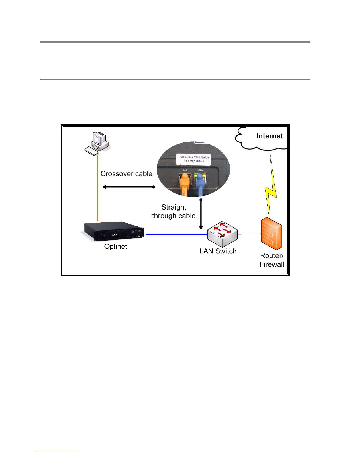
1. Connect a cross-over cable (included in your Accessories Kit) from the Optinet LAN
port to the network port on your workstation/laptop.
2. Connect a straight-through cable from the Optinet WAN port to an empty port on
your local network switch.
Figure 2.1 Optinet Configuration Connectivity
3. Write down the existing IP settings of your local workstation/laptop so that you can
easily change them back when configuration is complete.
4. Change your local workstation/laptop IP settings. You will need to change the IP
settings on your local workstation/laptop to communicate with the default settings of
Optinet:
• Default IP Address—192.168.1.80
• Default Subnet Mask—255.255.255.0
The suggested settings for the local workstation/laptop are the following:
• IP Address—192.168.1.81
• Subnet Mask—255.255.255.0
6
Page 15
Running the Setup Wizard
1. To access the Setup Wizard, open Microsoft’s Internet Explorer (IE) 6 or 7 and enter
http://192.168.1.80 in the address bar.
2. Login to the system using:
a. Default User Name: admin (all lowercase)
b. Default Password: blackbox (all lowercase)
3. Please read and accept the EULA agreement.
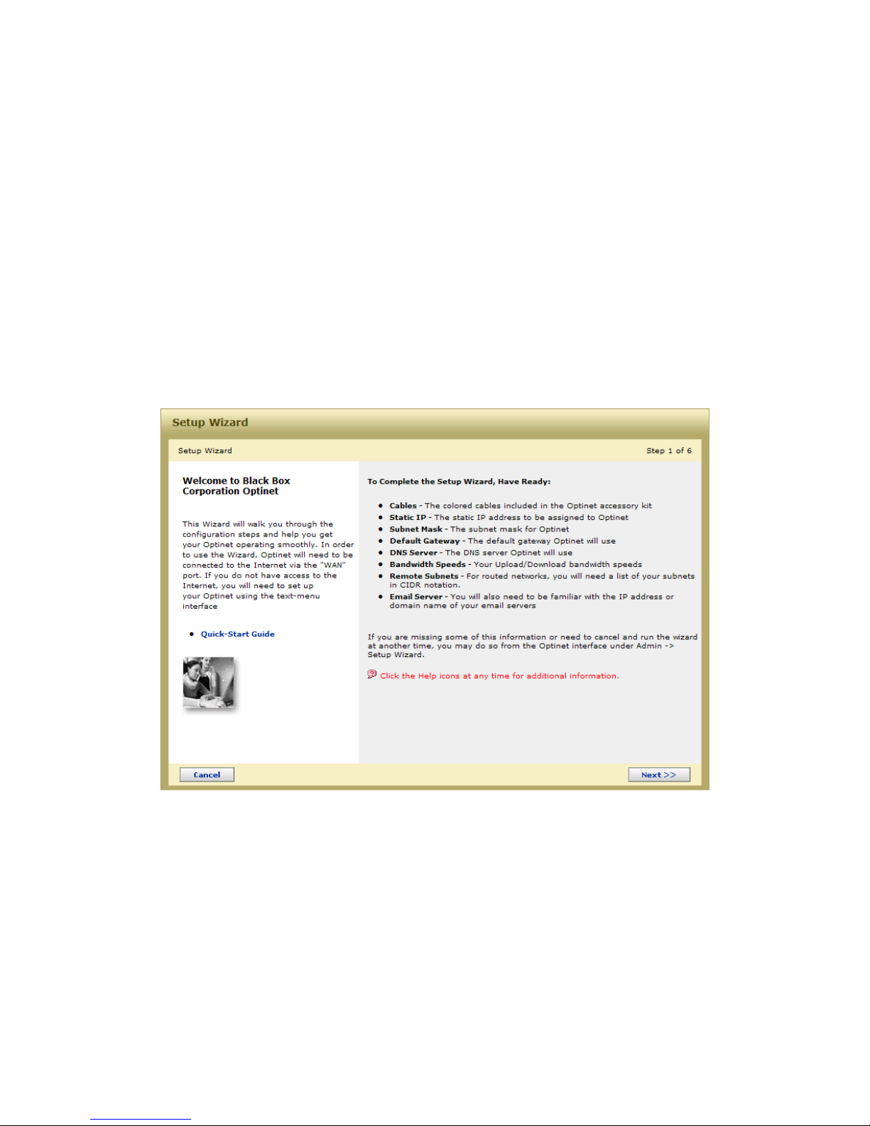
4. The Welcome Screen is then displayed automatically on new systems, as well as on
systems that have been reset to factory defaults. Read the following information
displayed in the Welcome Screen and select Next>>.
Figure 2.2 The Setup Wizard Welcome Screen
5. Using the information you collected in the section Gathering Initial Information,
complete the steps within the Setup Wizard. Select Next>> when the page fields
are complete. Optinet will test the settings of each step and if successful, will allow
you to proceed.
6. The final step in the Setup Wizard allows you to confirm and, if necessary, edit your
configuration. This step will also check for updates and will au tomatically retrieve
and install them. Major firmware upgrades will require a reboot of your system
when complete.
7
Page 16

Please note that advanced configuration options such as Directory Integration or Ethernet
Settings require additional steps that are not covered in the Setup Wizard. For additional
information, please review their corresponding chapters.
Cutting Over
Only perform these next steps when network traffic can be momentarily
interrupted.
Now that you have finished the Setup Wizard, you are ready to place Optinet inline with
Internet traffic. Optinet requires all Internet traffic to pass through its bridge interface,
unless the device is configured in Proxy Mode. If you are planning to configure Optinet in
Proxy Mode, you can skip the current section and proceed to the section Using Alternative
Configuration Methods.
For typical installations you will need to follow the next steps and physically place Optinet
inline with your network’s traffic. In general t his location is between the Firewall/WAN
Router and the Core Network Switch.
1. Remove the cables connected to The Optinet WAN and LAN ports.
2. If you modified your local workstation/laptop IP settings, you will need to change
your local workstation/laptop settings back to their original IP settings.
3. Locate the connection between the Core Network Switch and the Firewall/WAN
Router. Unplug the cable from the Firewall/WAN Router and connect it to the LAN
port on Optinet.
4. Using the cross-over cable, connect the WAN port of Optinet to the now open port on
the Firewall/WAN Router that was previously used by the Core Network Switch.
5. Verify that the cross-over cable is plugged into The Optinet WAN port and the
Firewall/WAN Router.
6. Verify that the straight-through cable is plugged into The Optinet LAN port and the
Core Network Switch. Optinet should now be sitting inline with your Internet traffic.
7. Confirm the Light Emitting Diodes (LEDs) for both the WAN and LAN ports are
posting solid green (link) lights and blinking amber (speed) light s.
8. Verify that local workstations can access the Internet by opening a web browser and
navigating to several web sites.
8
Page 17
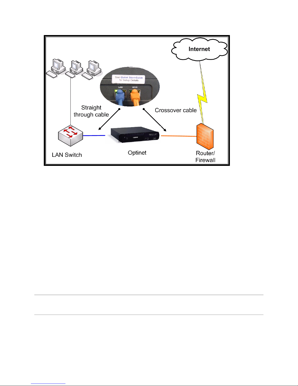
Figure 2.3 Optinet Installation Connectivity
If you are able to browse to the Internet, you have completed the installation of Optinet.
The device should now be sitting inline with your Internet traffic and monitoring web
requests.
Accessing Optinet
After completing the configuration and installation processes, you can access Optinet by
using the IP address you assigned to the device during the Setup Wizard.
1. Open Microsoft’s IE 6 or higher and navigate to http://IP address assigned.
2. Login using the default credentials (listed under the section Running Setup Wizard)
or with the newly created administrative login.
3. When you login to Optinet the Home Page will display. This page provides a
snapshot of system health, filtering effectiveness, current firmware versions,
subscription settings, as well as links to administration of your new system.
We strongly recommend that you create a new administrative login, and change the
default login password to limit access to Optinet. Select the Manage -> System
Access -> Logins link to make these changes.
9
Page 18

Using Alternative Configuration Methods
The previous sections discuss the most common steps for installing Optinet. However,
there are alternative methods that can be used for initial con figuration of the device as well
as different modes that Optinet can accommodate. In this section, the topics of installing
Optinet without the assistance of the Setup Wizard as well as Proxy Mode will be discussed.
Manual Configuration
Physical connectivity for manual conf iguration of Optinet can be accomplished using a crossover cable from a local machine (such as a laptop) to either the LAN, WAN, or
Management/Auxiliary (AUX) ports on Optinet. See the instructions in Connecting to
Optinet on modifying your local machine IP settings to connect to Optinet.
If you wish to configure Optinet without the assistance of the Setup Wizard, or if you are
pre-configuring the system for installation, the Manual Configuration settings can be
accessed through Admin -> Configuration settings screens. Simply cancel the Setup Wizard
and access the settings listed in the table below.
The following table shows where the network conf iguration information collected in
Gathering Initial Information can be manually entered into The Optinet configuration pages.
Quick Start Guide Table Name Admin -> Configuration -> Page Name
License Key License
IP Settings Setup
Total Upload/Download Bandwidth Misc. Settings
Email Settings Company Settings
Remote Subnets Remote Subnets
Management/Auxiliary Interface
Optinet can be accessed via the Management/Auxiliary port for th e initial configuration.
However, the IP settings for the port will need to be different than those for the bridge
interfaces (WAN and LAN ports) and cannot be an IP address found under the Remote
Subnets listings.
1. Connect a cross-over cable (included in your Accessories Kit) from The Optinet
Management/Auxiliary port to the network port on your workst ation/laptop.
2. Write down the existing IP settings of your local workstation/laptop so that you can
easily change them back when configuration is complete.
3. Change you local workstation/laptop IP settings. You will need to change the IP
settings on your local workstation/laptop to communicate with the default settings of
Optinet:
• Default Management/Auxiliary IP address—10.1.1.1
• Default Subnet Mask—255.255.255.0
10
Page 19

The suggested settings on the local workstation/laptop are t he following:
• IP address—10.1.1.2
• Subnet Mask—255.255.255.0
4. From the Management/Auxiliary port, you can access Optinet via the GUI or Text
Menu (covered in the following section). If you choose to configure Optinet via the
GUI, please follow the steps listed under the section Setup Wizard. If you choose to
configure Optinet via the Text Menu, please follow the steps listed under the next
section.
Text Menu Interface
The Optinet Text Menu allows installers, system administrators, and other trained technical
personnel to access the device via a text interface, similar to a Command Line Interface
(CLI). While some of the basic features and options available within the Optinet web
interface are also available here, most advanced technical options are only available through
the GUI menus. The one exception is IP Traffic Monitor (Option 2—Utilities, Option 3—IP
Traffic Monitor), which is discussed under Chapter 6: Administrating Optinet, section
Diagnostic Tools tab. Below are the supported options for accessing The Optinet Text Menu:
• Secure Shell (SSH)
• HyperTerminal (via serial connection)
The default login for all these menus is the following:
• Default User Name: menu (all lowercase)
• Default Password: blackbox (all lowercase)
Secure Shell Access
Secure Shell (SSH) access allows administrators to access The Optinet Text Menu through a
secure connection. SSH applications such as PuTTY (a freeware application available from
the installation CD) make it easy to use this secure method of accessing systems remotely.
1. Download PuTTY.exe from the CD.
2. Double click on the program.
3. Enter in the IP address of Optinet.
4. Leave all other settings at default.
5. Click the Open button.
11
Page 20
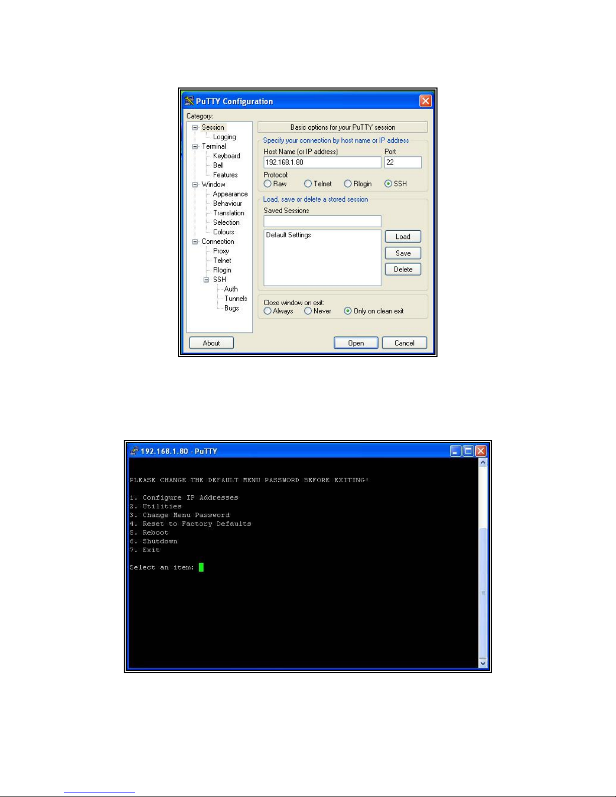
Figure 2.4 PuTTY Configuration
6. Login with the default credentials.
7. Type 1 to access Configure IP addresses submenu.
Figure 2.5 Text Menu Interface
12
Page 21

8. Enter in the information collected in the IP Settings table under Gathering Initial
Information.
Serial Access
The following section lists steps on how to connect to the Optinet Text Menu using
HyperTerminal. Although there are other terminal simulators that can work with the Optinet
serial connection, the steps listed below are for a workstation/laptop with Windows XP and
HyperTerminal.
Ensure that you have the null modem (2U systems) or USB (1U systems) cable (included
with shipping materials) connected to a communication port of your local workstation/laptop
and to the Optinet serial port (38.4 8N1).
1. Set up a connection using HyperTerminal (Start -> All Programs -> Accessories ->
Communications -> HyperTerminal).
2. In the New Connection Description dialog, enter a name for the connection in the
Name field and select an icon if you want.
3. Click the OK button.
4. In the Connect To dialog, select the COM port for the connection.
5. Click the OK button.
6. In the COM Port Properties window, select the settings that correspond to:
• Bits per second: 38,400
• Data bits: 8
• Parity: None
• Stop bits: 1
• Flow control: None
7. Click the OK button.
8. When the main HyperTerminal screen appears, press the Enter key to confirm a
connection.
9. Login with the default credentials:
a. Default User Name: menu (all lowercase)
b. Default Password: blackbox (all lowercase)
10. Type 1 to access the Configure IP addresses submenu.
11. Type the information collected in the IP Settings table under Gathering Initial
Information.
Once Optinet has been configured using an alternative method described above, you can
perform the steps listed under Cutting Over of this chapter.
13
Page 22

We strongly recommend that you change the default password for the menu account
to limit access to the Text Menu. Select Option 3—Change Menu Password under the
main menu to make this change.
Proxy Mode
For full functionality of Optinet, we recommend placing the device inline with traffic.
However, if you do not want to place the device inline with network traffic, or if you have
users on the WAN side of Optinet that you want to filter, you can configure Optinet as a web
proxy. A web proxy is normally a server that carries out web requests for users. Typically,
web traffic is routed to the server which requests the web sites for the intended users.
Optinet does likewise with a configuration called Proxy Mode. This configuration does not
require Optinet to be inline with network traffic.
To use Optinet as a proxy, the device must have a network connection to the users and the
Internet via the WAN or LAN port (only one has to be active). With this connection, you can
then use either the Setup Wizard or an alternative method to assign the device the required
IP settings. Afterwards, you must alter the connection settings of the users’ web browsers
to use the IP address of Optinet as a proxy and port 8888 for browsing. (Port 8888 is the
assigned port used by the Optinet filtering engine). If Optinet has a private IP address and
you want external users to use Optinet as a proxy, you may need to create a Network
Address Translation (NAT) rule for Optinet.
Below are the steps on how to alter the LAN connections using IE 7 and Firefox 2. You can
also alter LAN connections via Group Policy Objects (GPOs), VPN connections, or other
network devices; however, these steps are not covered in the User Guide and will need to
be researched independently.
Internet Explorer (IE) 7
1. Open up IE 7 web browser.
2. Click on Tools -> Internet Options.
3. Click on the Connections tab.
4. Click the LAN Settings button.
5. Under Proxy Server section, select the checkbox for Use a proxy server for your LAN.
6. Under the Address field, enter in The Optinet IP address.
7. Under the Port filed, enter in the number 8888.
8. Click OK until the settings are applied.
Firefox 2
1. Open up Firefox 2 web browser.
2. Click on Tools -> Options.
3. Click on the Advanced menu.
4. Select the Network tab.
14
Page 23

5. Under the Connection section, click the Settings button.
6. Select the radio button next to Manual proxy connection.
7. Enter in the IP address of Optinet in the HTTP Proxy field.
8. Enter in the number 8888 in the Port field.
9. You may also select the checkbox. Use this proxy server for all protocols as well if
you like.
10. Click OK until the settings are applied.
Once users’ web browsers have been configured to use Optinet as a proxy, you will then
need to configure Optinet to accept web requests. This setting is found under Admin ->
Configuration -> Advanced Setup. Select the check box next to Allow HTTP Connections on
port 8888. Don’t forget to apply the changes.
Optinet will then begin to create profiles for users as they begin t o send web requests to
Optinet. You can confirm this under Manage -> Directory Users & Nodes -> Network Nodes.
If you have enabled Directory settings, Optinet will also create Directory Profiles as well
(Manage -> Directory Users & Nodes -> Directory Users). You can then create groups
based on the profiles for content filtering and reporting. Please see Chapter 5: Managing
Optinet for steps on how to create groups.
Please note that Proxy Mode does not offer all functions over network traffic normally
associated when in the default inline mode, in particular band width control and full
reporting. Because network traffic is not physically passing through the Optinet bridge
interface, the device can no longer confirm which applications are passing nor control
bandwidth. In addition to this, you cannot use all of the Advanced Filtering options and
HTTPS/SSL Filtering settings to en sure content filtering.
With Proxy Mode you will only be able to filter web content and report on web sites visited.
As such, you will not be able to apply all Shaping Rules nor will there be data posted for
under the applications reports (Report -> Applications) or users reports (Report –> Users).
There will, however, be data under Internet Usage and Threats.
Below is a table of all supported reports and menus with Proxy Mode (Report and Manage
Tabs). If a specific feature is not listed in this table, then it is not supported in Proxy Mode.
Proxy Mode Support
Report Manage
Threats
Spyware Overview
Spyware Infected Users
Spyware Threat Names
Virus Overview
Virus Infected Users
Virus Threat Names
Policies & Rules
Groups
Time of Day Rules
Internet Usage Rules
o TFRS (HTTP Traffic Only) Deny Access,
No Filters, Web Filter Only, Web Logging,
SSL Block, and SSL Filter, Content
Filtering, Advanced Filtering, HTTPS/SSL
Filtering (SSL Certificate Based Content
Filtering), Web Authentication
Shaping Rules
o Web Content
15
Page 24

Policy Manager
Internet Usage
Web Hits Overview
Web Bandwidth Overview
Web Hits by Network Node
Web Bandwidth by Network Node
Web Time Online
System Reports
Active Users
CPU Utilization
IP Connections
Latency
Packets per Second
RAM Usage
Dashboard
Real Time URL Monitor
One final note: you can configure Optinet inline with traffic and use the device as a proxy
for a combination of functionality. For example, you can install Optinet inline with network
traffic for internal users, and then alter web browser settings for VPN or external users to
use Optinet as a proxy. This way, you gain full functionality for internal users and web
filtering functionality for external users.
Directory Users & Nodes
Directory Users
Directory Agent
Network Nodes
Broadcast Manager
Applications
Traffic Flow Rule Sets (HTTP Traffic Only)
Deny Access, No Filters, Web Filter Only, Web
Logging, SSL Block, and SSL Filter
Configuring Port Settings
The Optinet bridge ports (WAN and LAN) by default are set to auto-negotiate for both speed
and duplex settings. This means that Optinet will negotiate with the devices that are
plugged into these ports to verify their speeds and duplex mode. Normally auto negotiate
will allow Optinet to operate at least 100 Mbps or above and Full-Duplex.
However, you should confirm that Optinet is operating at least 100Mbps or above, FullDuplex, and is not generating any interface errors. You can do this under Admin ->
Diagnostic Tools -> Ethernet Status.
Review both WAN Port and LAN Port tabs to confirm that Optinet is operating at the correct
speed and duplex. Also verify that no errors are listed under the Errors field.
If the auto-negotiating settings list a speed under 100 Mbps, a duplex mode that is not Full
or are generating errors, you may need to hard set these settings on the interfaces. You
can do this under Admin -> Configuration -> Ethernet Settings.
Hard setting the Ethernet settings can cause network interruptions. Only perform these
next steps when network traffic can be momentarily interrupted.
Select the speed and duplex settings you would like to hard set for the desired port(s) and
press the Apply button. In addition to this, you may need to hard set the interface settings
on the devices connected to Optinet. This will allow Fail to Wire and No Failover to work
correctly. The next section will explain these options.
16
Page 25

Configuring Cabling
In addition to confirming the port and duplex settings, you should also confirm cables
connected to Optinet. Typically, layer 3 devices connected to Optinet require a cross-over
cable while layer 2 devices connected to Optinet require straight-through cables.
In a standard installation, the Optinet WAN port will connect to the firewall via a cross-over
cable while the Optinet LAN port will connect to the core network switch via a straightthrough cable.
However, if you are installing Optinet in between a firewall and the core network router, you
may need cross-over cables for each port. Also, if the devices connecting to Optinet offer
Medium Dependent Interface Crossover (MDIX), which can compensate for switching
transmit and receiving signals, you may be able to use straight-through cables for each
port.
In any case, you will want to confirm the cabling for proper negotiation for Fail to Wire or No
Failover. You can confirm negotiation by reviewing the section Ethernet Status. If after
hard setting the ports, Optinet is still generating errors, you may need to change the
cabling. After confirming negotiation, you should confirm Fail to Wire or No Failover by
following the steps listed in the next section.
Testing Fail to Wire or No Failover
Optinet offers two options for network connectivity in case of a device failure or power loss:
Fail to Wire and No Failover. Unless specified before purchase, the model of Optinet you
receive will be designed for Fail to Wire. Fail to Wire allows netw ork traffic to pass in case
Optinet fails or is powered down, while No Failover stops all network traffic in case of failure
or power loss. Your preference must be specified before purchasing the device as the
implementation is done via hardware. After confirming your preference and the installation
of Optinet, you should perform some tests to confirm the functionality.
Only perform this test when network traffic can be momentarily interrupted and
you are physically next to Optinet.
Fail to Wire
Fail to Wire allows network traffic to pass in case of failure by closing a circuit in between
the WAN and LAN ports. However, for this to work properly, the devices connected to
Optinet must be able to negotiate correctly.
1. Power off Optinet under Admin -> Utilities -> System Resets -> Hardware
Shutdown.
Do not power down Optinet by pulling the power cord or pressing the power
button on the front bezel. These procedures should only be used when there is no other
alternative for powering down the device.
17
Page 26

2. Depending upon the devices that are connected to Optinet, the duplex settings and
cabling, it may take up to 5 minutes for Fail to Wire to complete. As such, please
wait up to 5 minutes after powering down Optinet completely before performing the
next step.
3. Confirm by the interface LEDs that the firewall/WAN router and the core network
switch are still communicating.
• Confirm that all ne twork options are available, i.e., browse the Web, log into
a remote site, etc.
• If the test is not successful, check the compatibility of port speed/duplex and
cabling used on Optinet and the other devices.
4. Power on Optinet using the power button on the front bezel.
5. After waiting 5 minutes for the device to power up, log into Optinet and verify that
the unit is functional.
Bypass Mode
Besides powering down Optinet, there are other scenarios that can cause Optinet to fail,
i.e., running the device out of specs, hardware failure, etc. Once a failure is detected,
Optinet will initiate the supported Bypass Mode (Fail t o Wire or No Failover). This is
indicated by the LEDs on all ports, which will blink and scroll in unison.
If this happens, please contact Black Box Network Services Technical Support at 724-7465500 or your Authorized Black Box Network Services Reseller. Diagnosing and
troubleshooting the problem may require that you phys ically remove Optinet from the
network.
No Failover
No Failover works by simply grounding the circuit in between the WAN and LAN ports of
Optinet. As such, when a failure is detected, all traff ic will not be passed from the LAN port
to the WAN port; thereby denying Internet access.
1. Power off Network under Admin -> Utilities -> System Resets -> Hardware
Shutdown.
Do not power down Optinet by pulling the power cord or pressing the power
button on the front bezel. These procedures should only be used when there is no other
alternative for powering down the device.
2. Depending upon the devices that ar e connected to Optinet, duplex settings, and
cabling, it may take up to 5 minutes for No Failover to complete. As such, please
wait up to 5 minutes after powering down Optinet completely before performing the
next step.
3. Confirm by the interface lights that the firewall/WAN router and the core network
switch are not communicating.
• Confirm that all network options are not available, i.e., attempt to browse the
Web, log into a remote site, etc.
18
Page 27

• If the test is not successful, check the compatibility of port speed/duplex and
cabling used on Optinet and the other devices.
4. Power on Optinet using the power button on the front bezel.
5. After waiting 5 minutes for the device to power up, log into Optinet and verify that
the unit is functional.
As with Fail to Wire, there are other scenarios that can cause Optinet to fail besides
powering down the device. If Optinet is entering No Failover unintentionally, please contact
Black Box Network Services Technical support at 724-746-5500 and/or your Authorized
Black Box Network Services Reseller for diagnosis and troubleshooting.
Now that you have confirmed Fail to Wire or No Failover, let’s discuss how to navigate
through the Optinet GUI.
19
Page 28

Chapter 3: Navigating Optinet
This section contains guides and tips on how best to navigate through The Optinet Graphical
User Interface (GUI). The chapter is divided into three sections:
• General Navigation
• Task Pane
• Help Pane
To access Optinet, open up Microsoft’s Internet Explorer (IE) 6 or higher and enter in the IP
address assigned to Optinet in the address bar (Optinet only supports IE 6 and above). You
should receive the login menu.
General Navigation
Once you login to Optinet, you will be presented with the Home Page. The Home Page
provides a snapshot of system health, filtering effectiveness, current firmware versions,
subscription settings, as well as links to guide the administration of your system.
The Optinet navigation is divided into three tabs: Report, Manage, and Admin. Each tab
presents you with different functions for Optinet. When you click on one of the tabs, the
expanded menus for those tabs will appear. You can then select a sub-menu under the
corresponding tabs for more options which will appear as expandable selections.
In general, the Report tab will be used for generating reports and viewing network t r affic.
The Manage tab will be used to create groups, content filtering rules, and shaping rules.
The Admin tab is used for basic and advanced configuration of the device, as well as
troubleshooting and disaster recovery.
20
Page 29
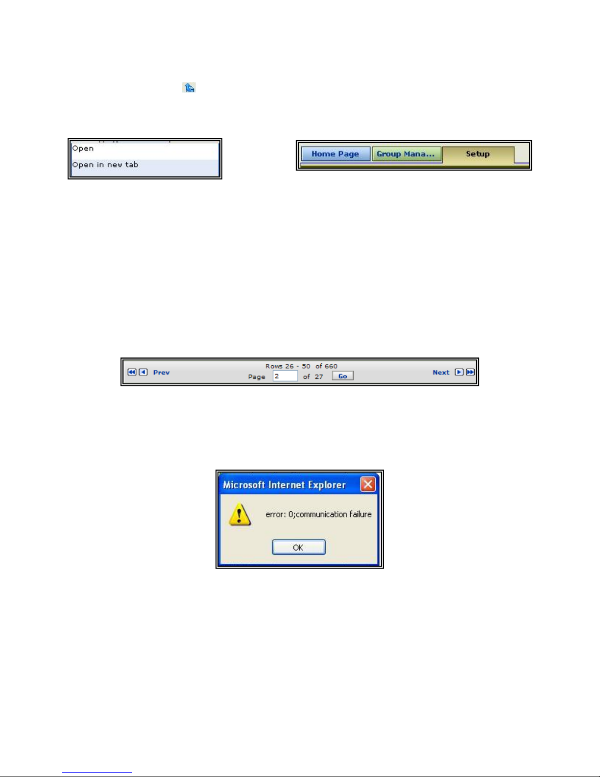
You can navigate back between tabs and reports by using the back arrow button located
next to the Admin tab
. Do not use the back arrow button available on your web browser
since this will take you back to the Optinet login page. You can have multiple tabs open for
ease of use by right-clicking a selection and choosing Open in new tab. Each tab color will
correspond to the main menu tab color.
Figure 3.1 Optinet Navigations tabs
For large reports, group membership, or application menus, Optinet has a pagination menu
that can be used to navigate to specific pages or towards the end or beginning of a series.
The open box in the pagination menu allows you to view a certain page after entering the
page number and clicking the Go button (the available pages are listed above the open
box).
You can also navigate to the next (Next) or previous (Prev) page by clicking the single
arrow or to the very end or beginning of the series by clicking the double arrows. Where
available, the pagination menu will post towards the bottom of the report, membership box,
or application menu.
Figure 3.2 Optinet Pagination arrows
Finally, depending upon which tasks are being performed, you may receive a
communication error from Optinet. This is usually a result of services being restarted. If
you are presented with the below dialog box, select the OK button, wait 30 seconds, and
attempt to access a menu. If the problem persists, you may need to re-login to Optinet.
Figure 3.3 Communication Error Dialog Box
Now that you have become familiar with general navigation, let’s explain the Tasks Pane,
Help pane, and the different navigation options available.
21
Page 30

Tasks Pane
The Tasks Pane is located in the upper–right corner of any of the Optinet screens. The
Tasks Pane lists actions or options that can be selected for the active page. Because of this,
the contents displayed in the Tasks Pane will change depending on the screen currently
displayed. The Tasks Pane is a great help that will post common accessible actions.
For example, if you select a report, the Tasks Pane will list options on how to present the
report, i.e., Email, Print, Export, etc. These actions are available by clicking on the Tasks
Pane icons located in the Tasks Pane.
Below are listed all options presented in the Tasks Pane with the corresponding action.
Please review Chapter 4: Generating Reports for more information on some of the options.
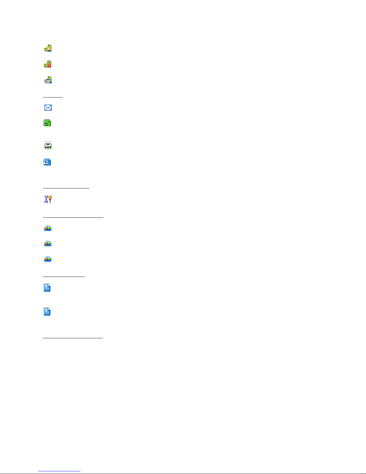
Actions
Re-scan Port: This will re-scan profiles under Netw ork Node Manager (Manage -> Directory
Users & Nodes -> Network Nodes). Use this action when a device needs to be re-scanned
due to configuration changes, i.e., new NetBIOS name, new IP address, etc.
Re-scan Directory User Name: This will re-scan profiles under Directory Users (Manage ->
Directory Users & Nodes -> Directory Users). Use this action when Directory Users need to
be re-scanned due to configuration changes, i.e., new domain, new groups, changed name,
etc.
Actions
Correlate by
—Directory User Dashboard: Displays Directory User Overview
—Directory User Detail: Displays Directory User Detail for selected Directory User profiles
—Network Node Overview: Display the Network Nodes Overview report
—Network Node Detail: Display all details for the Network Node selected
—Download Certificate: Download the SSL Certificate
—Category: Correlate report by Web categories visited
—Directory User: Correlate report by Directory User profiles
—File Type: Correlate report by File Types downloaded
—Group: Correlate report by Group profiles
—Host: Correlate report by Web sites (hosts) visited
—MIME Type: Correlate report by MIME Types downloaded
22
Page 31
—Network Node: Correlate report by Network Node profiles
—None: No correlation
—Service: Correlate IM reports by IM Client service
Export
format
(XML) document
Getting Started
Related Dashboards
—Email: Send the report in an email
—Excel Document: Export the report or polices into a Comma Separated Value (CSV)
—Print: Print the report or polices currently displayed on screen
—XML Document: Export the report or policies into an Extensible Markup Language
—Getting Started Videos: Watch tutorial videos on the corresponding topic
—Directory User Dashboard: Display all traffic reported for the Directory User selected
—Group Dashboard: Display all traffic reported for the group selected
—Network Nodes Dashboard: Display all traffic reported for the Network Node selected
Related Tasks
—View Bandwidth Report: View amount of bandwidth consumed for selected Web
category, Web site, or profile
—View Hits Report: View amount of URL hits for selected Web category, Web site, or
profile
System Information
System Information will post current system time. If your device does not post the correct
time, you may need to adjust the Time Zone settings or the Network Time Protocol (NTP)
server. Please review the sections Setup and Advanced Setup in Chapter 6: Administrating
Optinet.
Help Pane
The Help Pane lists topics from the User Guide that are related to the page currently posted.
For example, if you select the Application Overview report, the Help Pane will list Related
Topics for the Application Overview. You can then select th e link which will display the first
23
Page 32

page within the User Guide dealing with the Application Overview. You must have Adobe
Reader installed to use the Help Pane.
The Help Pane also posts information regarding the Product Enhancement Program. The
Product Enhancement Program allows Black Box Network Services to upload a small file
containing anonymous configuration and system usage details as part of the scheduled
update routine. This file will not contain personal identifiable information, will not be us ed
for direct marketing, and will not impact system performance. The produc t details collected
as part of the Product Enhancement Program may change from time to time as new
features and capabilities are added to or changed in the product , but they will never include
personal identifiable information. You can stop participat ing at any time by disabling the
checkbox located in the Product Enhancement Program.
One last item under the Help Pane is Black Box Network Services Optinet Privacy Policy.
The privacy policy covers how Black Box Network Services will handle personal in formation
collected and received with Optinet. For full details on this information, you can select the
link for Black Box Network Services Optinet Privacy Policy under the Help pan.
Lastly, the Tasks Pane and Help Pane are collapsible by selecting the collapse icon located to
the right of the Tasks Pane.
24
Page 33

Chapter 4: Generating Reports
The Report tab will present information concerning network traffic, web sites visited, and
system health. This chapter is divided into each report available and also general reporting
rules that will apply to each different report.
• Home Page
• General Reporting Options
• Users Tab
• Applications Tab
• Threats Tab
• Internet Usage Tab
• System Reports
• Dashboards Tab
Home Page
The first page presented under the Report tab is the Home Page. The Home Page is divided
into 5 sections: Message Center, System Notifications, Getting Started, Hardware Settings,
and System. The top display will be the Message Center.
The Message Center
The Message Center posts message about firmware and software releases. The Message
Center will also post important suggestions such as changing default passwords and
25
Page 34

company communications. These messages are posted by date and can be read by
selecting the individual messages. Afterwards, you may delete the messages by either
selecting the trash icon next to the message or by clicking the delete button inside the
messages.
System Notifications
System Notifications will post messages from Optinet. These messages are intended to
alert the administrator of Optinet of critical configuration or incompatibility issues that may
impede proper Optinet functionality. Messages such as incorrect installation, exceeded
license count, or network scenarios such as asymmetrical routing that require advanced
configuration will be posted here. These messages will be posted in their entirety on the
System Notifications area. You may delete the messages by selecting the trash icon next to
the message; however, the message may return if the problem is not resolved.
Getting Started
The Getting Started area provides you with links to the User Guide that may be helpful in
beginning administration of the Optinet System.
Hardware Settings
The Hardware Settings area provides you with a summary of the Optinet hardware settings,
i.e., Model, Serial number, and Device ID. This area also posts the device’s Licensed Nodes,
Software Version, Last Known Updates, System Time, and expiration date of Annual
Software Maintenance (ASM).
ASM is used for support on your device and provides Optinet with continued updates on
firmware, spyware, anti-virus, and content filtering. ASM also grants you access to Black
Box Network Services Technical support if needed. If your ASM is not current, Optinet will
not be able to update firmware, software, content filterin g, spyware or anti-virus nor will
Black Box Network Services Technical support be available. To renew your ASM please
contact Black Box Technical Support at 724-746-5500, your Authorized Black Box Network
Services Reseller, or a Black Box Network Services Sales Office.
System
The System area provides you with a summary of the Optinet monitoring statistics and
system information such as blocked spyware, blocked viruses, blocked web requests, and
average CPU load. Totals for each parameter are displayed for the last 24 hours.
General Reporting Options
There are several options available that are universal under the Report Tab. These options
are Selected Date, Search, Correlated by, Result Type, Group, Network Node, Directory
User, and Encryption Type. These options allow you to customize reports on any device,
user, or application.
26
Page 35

Figure 4.1 Reporting Options
For example, click on the Application Overview report (Report -> Applications -> Application
Overview). This will post the top applications passing traffic through the network within the
last 24 hours. However, if you would like to search for traffic from a specific device within
the last 30 days, you may adjust the Selected Date and search for device under Network
Node. The report will then modify to display the last 30 days for the specific device. These
same options can be used for a wide variety of reports.
Below are listed all available adjustments with reporting. You may also click on the different
settings contained within the specific reports for a list of available options.
Selected Date
Selected Date allows you to adjust the time frame for the generated report. The options
available are Last Hour, Last 24 Hours, Last 7 Days, Last Week, Last 30 Days, Last Month,
Last Year, and Custom.
If you select Custom, you will be presented with a calendar that will allow you to adjust the
time and days accordingly.
Search
This field will allow you to search for different sections in report s, i.e., specific web sites,
categories, applications, etc. Enter in the search criteria and click the Search button (or
press the Enter key) for results.
Correlated by
This field allows you to link traffic reports to the most bandwidth consuming users (Group,
Directory User, and Network Nodes) for specific applications. You can also use the field to
link Internet Usage reports by the most browsed web Categories, Hosts, File types, and
MIME Types.
Result Type
This field is available under Web Content reporting. This opt ion allows you to customize
web reports based on the four general areas of web sites: No Filter (All web sites
requested), Allowed (web sites that have been accessed), Blocked (web sites that have
been blocked), and Bypassed (web sites that were bypassed using the Bypass Password).
Group
This field will allow you to search for specific Groups. Clicking this field w ill populate the
Select Filter Group box. Search the Available Groups list for the desired Group profile,
select the profile and click the Add button. Then click the OK button to run the report.
27
Page 36

Network Node
This field will allow you to search for specific Network Nodes (devices on the n etwork).
Clicking this field will populate the Select Filter Net work Node box. Search the Available
Network Node list for the desired Network Node Profile, select the profile and click the Add
button. Then click the OK button to run the report.
Directory User
This field will allow you to search for specific Directory Users. Clicking this field will populate
the Select Filter Directory box. Search the Available Directory Users list for the desired
profile, select the profile and click the Add button. Then click the OK button to run the
report.
Encryption Type
This field is available under Web Content reporting. This opt ion allows you to customize
web reports to display all web requests (No Filter), typical web requests that use Hypertext
Transfer Protocol-HTTP (No Encryption), or web requests that use Secure Hypertext
Transfer Protocol—HTTPS (Secure Socket Layer-SSL). Chapter 8: Implementing HTTPS/SSL
Filtering with Optinet discusses this topic in more detail.
Application Set
This field is available under Application Overview and some detail reports. This option will
allow you to filter reports by Application Sets. For more information on Application Sets
please see the section Applications Tab in this chapter.
Right-Click Options
Right-click options allow you to customize reports using specific time, users, or devices. For
example, to view specific applications under Application Set reports you can use right-click
options to post the report. Go to Report -> Application -> Application Set Overv iew . This
report will display all application sets passing through the network within the last 24 hours.
Select an application set, and right-click on the title. You w ill be presented with several
options that will allow you to correlate the report. Select Correlate by Application to view
the exact applications within the Application set.
Figure 4.2 Right-click Options
Selecting this option will post the specific applications being us ed under the application set.
Using right-click options will allow you to quickly access different correlations under all
reports. If you are not sure how to retrieve detailed information within a specific report,
right-clicking will present you with the most common options for the report. Other right click options available are correlations by Groups, Network Node, Directory User, etc.
28
Page 37

Drop-Down Arrows
Another option that allows you to customize reports is the Drop-Down Arrows. Any of the
reports available can be collapsed by using the Up arrow icon
corresponding menu bar. You can also expand an area in the Report tab using the Down
arrow icon
.
on the right side of the
Bar-Pie Graph Drop-Down
Some reports allow you to choose the graph types of either Bar Graphs or Pie Graphs.
Where this is available, you will be presented with a Drop-Down Box located in the Graph
title that will make available a bar graph or pie graph for the report.
Figure 4.3 Bar-Pie Graph Drop-Down
Snapshot-Real Time Drop-Down
The Snapshot-Real Time Drop-Down Menu allows you to view selected information
historically or in real time.
For example, if you are reviewing the report of Web Hits by Category (Report -> Internet
Usage -> Allowed) the default settings will post the results by Snapshot within the last 24
hours (historically). If you select the option of Real Time, the report will change and display
actual web hits as they pass through the device at the moment.
This option is found under Internet Usage reports (Report -> Internet Usage) and is a great
tool for troubleshooting and identifying problematic users or web sites as they occur.
Figure 4.4 Snapshot-Real Time Drop-Down
Real Time options also allow you to correlate reports by Network Node, Directory User,
Groups, and other criteria. This is useful for confirming problems immediately and
preventing them with less response time. For example, if a user is attempting to visit a
prohibited site, you can verify the web sites he or she is visiting right now by correlating
these reports by Network Node or Directory User.
Report Recommendations
Optinet is capable of reporting on a tremendous amount of information. Active users, web
sites visited, and general overviews of applications are examples of the reports most readily
available. Please keep in mind that while Optinet is recording information for reporting, the
device is also filtering web traffic and shaping network applications. This requires that
Optinet share resources between the different operations being performed.
Because of this, priority is given to filtering and shaping so that reporting does not consume
resources that may impact network performance. Optinet has a default timeout limit of five
minutes for reports to complete. This is done to ensure reporting will not consume needed
29
Page 38

resources for other operations. If a report cannot complete within the five minutes, you will
receive a timeout message.
If you receive a timeout message, you may alter the time limit under the Advanced Setup
menu (Admin -> Configuration -> Advanced Setup -> Database Timeout). You can allocate
up to 15 minutes for reports to complete. Don’t forget to Apply the changes. This will allow
the database to dedicate more time to complete the report and post the results.
Nonetheless, detailed reports that span large amounts of time and cover multiple users or
applications may better be executed during non-peak traffic times; thus allowing more
resources for Optinet to complete the report without running the risk of affecting network
traffic or filtering and shaping rules.
In addition to running detailed reports during non-peak traffic times, you can also use
Summary Tables to expedite reporting results. Summary Tables allow Optinet to
summarize or condense large web reports, allowing for a faster response time with Internet
Usage reports. This utility will index web reports and correlations for all reports once the
option is selected. Summary Tables also decrease dependency on shared resources.
To enable Summary Tables go to Admin -> Configuration -> Advanced Setup and select the
checkbox next to Enable Summary Tables. This will begin indexing web requests to allow
for faster Internet Usage reporting. Please note that the Enable Summary Tables option will
only begin summarizing from that point forward. If you would like to summarize previous
data gathered before Enabling Summary Tables, you will need to run the Conversion Utility.
The Conversion Utility will take previous data that has not been summarized and create a
summary table for that information. There are three options for converting previous data:
Web Request Summary Table, Level 1 Summary, and Level 2 Summary. Web Request
Summary Table will summarize all Web requests data. Level 1 Summary Table will
summarize the first correlation for those reports, i.e., first correlation by Category, Host,
File Type, MIME Type, Group, Directory User, and Network Node. Level 2 Summary Table
will summarize the second correlation for those reports, i.e., second correlation by
Category, Host, File Type, MIME Type, Group, Directory User, and Network Node.
The Conversion Utility is located under Admin -> Configuration -> Advanced Setup -> Run
Conversion Utility Now. Once selected, you will be presented with the three different levels
of conversion: Web Request Summary Table, Level 1 Summary Table, and Level 2
Summary Table. You can then select the Start Conversion Now button next to each level to
activate the conversion.
The Conversion Utility places additional load on Optinet and may consume a large amount of
processes. Because of this, we strongly recommend that you run the Conversio n Utility
during non-peak hours to avoid unnecessary interruptions in network traffic. Also note that
you can only run one conversion at a time, and they must be done in order.
This concludes the section on general reporting options. In the next sections we will discuss
the different reports for application and web traffic.
Users tab
The Users tab gives you an overview of the Internet traffic generated on your network by
users. This report will display the top 25 users, devices, or groups on your network within
30
Page 39

the last 24 hours. However, this time frame is customizable as well as sorting features.
This report will display total network traffic as well as total download and upload for the
corresponding criteria. The reports available are Directory User Overview, Group Overview,
and Network Node Overview. Also available under this report are Directory User Detail,
Group Detail, and Network Node Detail reports. These reports are often referred to as
Dashboard reports.
Dashboard Reports
Dashboard Reports are detailed reports about individual users, devices, or groups. They
present all information available about the selected device, user, or group. For example, go
to Report -> Users -> Network Node Overview. Under the Network Node Details legend,
select any profile and click on the name. This will populate the Network Node Detail report
for the particular device.
Dashboard Reports display all recorded information for the profile selected. The reports
available are listed below:
• Total Traffic—this traffic is the combined amount of upload and download traffic.
• Application Traffic—this traffic is the amount of bandwidth consumed for all
applications.
• Uncategorized Traffic—this is traffic that Optinet does not recognize.
• Web Requests by Host—these are the host name of Web sites visited by the user,
device, or group.
• Web Request by Category—these are categories of Web sites visited by the user,
device, or group.
• Possibly Infected Spyware—these are Web sites visited or applications used by the
user, device, or group that are possibly infected with spyware.
• Possibly Infected Virus—these are Web sites visited by the user, device, or group
that are possibly infected with Web viruses.
• Open ports—these are all ports active by the user, device, or group and their
corresponding service.
• Network Node Information—this report will post the Operating System (OS) as well
as the assigned group for the device.
If you need more detail on the individual reporting aspect, simply select the title of the
report for a more comprehensive representation.
To display dashboards for different users, devices, or groups, select the profile name located
in the upper right-hand corner of the original dashboard.
Applications tab
The Applications tab displays the amount of bandwidth used by applications and application
sets. These reports are presented in total downloads and uploads according to colors and
amounts. When data is presented as a bar graph, the corresponding Network Node,
31
Page 40

Directory User, Group or application will be posted next to a colored bar. When data is
presented as a column graph, the most recent data is presented at the right end of the
graph with the green column representing download traffic and the blue column
representing upload traffic.
Optinet identifies traffic based on application signatures. Applications can then be grouped
into application sets (signature sets) of programs that perform a comparable purpose. For
example, the signature set of Remote Desktop/Remote Control/X Traffic comprises the
applications of PC Anywhere, Citrix, GoToMyPC, Microsoft’s Remote Desktop, and many
more. For a complete list of application sets, please see Chapter 5: Managing Optinet.
Also available in this tab are Custom Application Sets and Uncategorized Reports. Custom
Application Sets report on traffic for which Optinet administrators have defined a custom
signature. Uncategorized Reports presents specific stats of applications for which Optinet
does not have an explicit signature. Although Optinet may not have a signature for this
traffic, the device will record the protocol used, the destination port and the percent of
bandwidth used.
The application sets are listed below as bulleted items.
• Application Overview—this is a summary of bandwidth consumed by individual
applications.
• Application Set Overview—this is a summary of bandwidth consumed by application
sets.
• Total Traffic—this is the amount of total bandwidth consumed.
• Chat and IM—this is the amount of bandwidth consumed by Chat and IM
applications.
• Databases—this is amount of bandwidth consumed by Database applications.
• DNS/Naming/Locators—this is the amount of bandwidth consumed by DNS and other
network naming applications.
• Email/Collaboration—this is the amount of bandwidth consumed by Email and
services used to send email.
• FTP/File Transfer—this is the amount of bandwidth consumed by File Transfer
Protocol applications.
• ICMP Traffic—this is the amount of bandwidth consumed by Internet Control Message
Protocol applications.
• Games—this is the amount of bandwidth consumed by online gaming applications.
• HTTP—this is the amount of bandwidth consumed by Hypertext Transfer Protocol
(Web) applications.
• NetBIOS/MS File Service—th is is the amount of bandwidth consumed by Network
Basic Input/Output and other Microsoft File Service applications.
• Network Mgt/Monitoring—this is the amount of bandwidth consumed by network
management applications (SNMP, NMS, etc.).
32
Page 41

• Network Routing—this is the amount of bandwidth consumed by network routing
applications (RIP, NCP, etc).
• Network Utility—this is the amount of bandwidth consumed by network ut ility
applications (DHCP, NSW, etc.).
• Peer 2 Peer—this is the amount of bandwidth consumed by Peer 2 Peer applications.
• Printing and Reporting—this is the amount of bandwidth consumed by printing and
reporting applications.
• Proxy and Cache—this is t he amount of bandwidth consumed by Proxy and cached
applications.
• RPC/Remote Execution—this is the amount of bandwidth consumed by remote
execution applications.
• Remote Desktop/Remote Control/X Traffic—this is the amount of bandwidth
consumed by remote desktop and control applications.
• Security/Authentication—this is the amount of bandwidth consumed by security
applications.
• Streaming Media—this is the amount of bandwidth consumed by streaming media
(music and video) applications.
• Telnet/SSH—this is the amount of bandwidth consumed by Telnet and SSH
applications.
• Uncategorized Traffic—this is the amount of bandwidth consumed by traffic that has
no explicit signature set.
• VIOP and Voice Chat—this is the amount of bandwidth consumed by Voice over
Internet Protocol (VoIP) and Voice Chat applications.
• VPN and Tunnel—th is is the amount of bandwidth consumed by VPN and Tunneling
applications.
Threats tab
The Threats tab will report and provide a detailed view of all activity in y our net work
relating to Spyware and web viruses. These reports will present information on Spyware
and Web viruses and possibly infected devices in your network. You can then use Optinet to
identify possible threats before they become problematic.
• Spyware Overview—this is a summary of spyware threats that have been blocked.
• Spyware Infected Users—these are devices that may be infected with spyware.
• Spyware Threat Names—these are the names of spyware threats present on the
network.
• Virus Overview—this is a summary of web viruses that have been blocked.
33
Page 42

• Virus Infected Users—these are devices that may be infected with web viruses.
• Virus Threat Names—these are names of web virus threats present on the network.
Internet Usage tab
Internet Usage tab reports on all web sites requested by users. This is a great report to
give a general indication of which web sites and categories users are visiting or attempting
to visit.
One of the reports, Web Time Online, is a report based on estimated values and generated
by counting the number of hits per page multiplied by the value entered in Miscellaneous
Settings (Admin -> Configuration -> Misc. Settings).
As with most online timers, there is not a definite method for determining if a user is
actively surfing the Web or merely has a program in the background generating hits, i.e.,
weather report, stock ticker, or Internet radio. As such, these are estimates and not exact
values.
• Web Hits Overview—this report is presented in three categories: Allowed, Blocked,
and Bypassed. Allowed refers to web hits on sites that users have been allowed to
visit. Blocked refers to blocked web hits on sites that users have not been allowed to
visit. Bypassed refers to web hits originally blocked on sites but were later allowed
as users entered in the Bypass Password (for more information on this sett ing see
Chapter 5: Managing Optinet). Clicking on each cat egory will present all information
pertinent to category. For example, clicking on Allowed will show you all hits for
Web categories that users were allowed to visit. This will also post the percentage in
comparison to the total number of hits for the Allowed category. You can correlate
this report by Host, File Type, MIME Type, Group, Directory User, and Network Node.
• Web Bandwidth Overview—this report displays how much bandwidth is being
consumed by web requests. The report is presented in a similar format of web Hits
Overview (Allowed, Blocked, and Bypassed) with a column graph showing the
amount of bandwidth for Web requests. This report can be modified for specific
dates, correlations, result types, and other features.
• Web Hits by Network Node—this report shows the top users of web traffic in terms of
hits. This reports display a bar graph which shows the top users followed by a detail
view of the corresponding profiles, number of hits, and percentage of the users’ Web
hits compared to total web hits.
• Web Bandwidth by Network Node—this report shows the top users of Web traffic in
terms of bandwidth. This report shows you the Hardware Profile (Network Node) and
its corresponding download total, upload total, total bytes, and percentage of
bandwidth consumed for web traffic.
• Web Time Online—this report displays the amount of time users have spent browsing
the Internet. Please remember that this report is an estimation of time spent
browsing the Internet and is not an exact value.
34
Page 43

System Reports tab
System Reports tab reports on the actual system health of Optinet. This report posts the
CPU and RAM utilization of the device. The report will also post the active connections in
the network as well as requests for Directory Users. Understanding this report will allow
you to schedule maintenance, plan for upgrades, and prevent problems on the network or
with Optinet.
• Active Users—this report refers to active devices present on the network.
• CPU Utilization—this report refers to how much of the Central Processing Unit (CP U)
Optinet is utilizing.
• Directory Agent Requests—this report lists how many requests Optinet has sent to
the Directory Agent installed on your directory server. For this report to post
information, Directory Users must be integrated with Optinet. Please see Chapter 7:
Integrating Directory Users with Optinet for more information.
• IP Connections—this report refers to live IP flows traversing through Optinet.
• Latency—this report shows in milli s econds the response time for PING requests sent
from Optinet to the network’s default gateway.
• HTTP Connections—this report shows the number of connections per second to Web
sites being filtered by Optinet.
• HTTP Requests—this report shows the number of Web requests per second Optinet
has filtered.
• Packets per Second—this report displays the number of Internet packets per second
passing through Optinet.
• RAM Usage—this report shows the amount of Random Access Memory (RAM) Optinet
is using.
• SSL Connections—this report shows the number of HTTP Connections that have been
established with SSL. For this report to function, Optinet must be configured for
HTTPS/SSL Filtering. For more information on this feature, please see Chapter 8:
Implementing HTTPS/SSL Filtering with Optinet.
Dashboards tab
The Dashboards tab presents two tools that demonstrate traffic and Web request in real
time. These tools are Real Time Monitor (RTM) and Real Time URL Monitor (RTUM).
RTM displays traffic amounts as they happen. This can be helpful in troubleshooting
network problems or resolving bandwidth issues in real time. RTM will post total application
traffic, both upload and download, with a legend representing distinct applicat ions. RTM
parses traffic in three second intervals and display the amounts accordingly.
35
Page 44

Figure 4.5 Real Time Monitor
Figure 4.6 Real Time Monitor Legend
36
Page 45

Another capability of RTM is the ability to correlate with in the last hour to display the most
bandwidth consuming users. For example, in the above diagram RTM has HTTP as the
highest amount of traffic. If you right-click on this traffic, you will be presented with the
options to correlate by Directory User, Group, or Network Node.
Figure 4.7 Real Time Monitor Right-Click Options
You can then select Correlate by Network Node to confirm what devices within the last hour
have consumed the highest amount of HTTP traffic. RTM can be used to diagnose a
problem in actual time; thus allowing you to resolve the issue as soon as possible.
RTUM displays web requests as they pass through Optinet. This tool, in addition to RTM,
can be used to confirm instantaneously the web sites that are being accessed, blocked, or
bypassed. You can also use the different options to display the web requests for a specific
Network Node, Directory User, and Group as well as the Date, Web category and Encryption
Type of the request.
Figure 4.8 Real Time URL Monitor
This concludes the chapter on generating reports. The next chapter will guide you on how
to manage Optinet in regards to creating groups, implementing policies, and managing
devices and traffic.
37
Page 46

Chapter 5: Managing Optinet
Optinet allows you to control and identify network traff ic based on applications and users.
Optinet also allows you to separate problematic users from general traffic or problematic
applications based on different criteria, time of day, and priority. The device can also block
web sites or categories protecting users and your network from improper content. Optinet
can also allocate resources to identify proprietary traffic within your network, thus
customizing the device to your specific needs. Most of these options are available under the
Manage tab and are covered in this chapter:
• General Manage Options
• Policies & Rules tab
• Directory Users & Nodes
• System Access tab
• Application tab
General Manage Options
The Manage tab is where policies and organization of users will be enf o rced. Under this tab,
you will create groups, time of day rules, content filtering rules, and shaping rules. This tab
also allows you to customize traffic identification and select which devices or us ers will or
will not be monitored.
The basic principles behind the Manage tab are “Who, When, What, and How.” “Who” will
define which users will be assigned to which groups. “When” will define what time during
the day the rules take effect, i.e., all day, 9am to 5pm, etc. “What” will define the allowed
content and applications, and “How” will deal with correlating specific policies to the
38
Page 47

corresponding groups. Each menu under the Policies & Rules tab addresses these
principles:
• Groups—who will be in the group?
• Time of Day Rules—when will the rules take effect?
• Internet Usage Rules—what web sites can group members visit?
• Shaping Rules—what applications can group members access?
• Policy Manager—how to correlate rules to groups?
As a general rule, these principles must be in line with these steps. For example, once you
create a group, you will then want to define a Time of Day Rule (TDR) and an Internet
Usage Rules (IUR). After those steps, you will create a shaping rule and tie all pieces
together with the Policy Manager.
In addition to these steps, please note that the more information you have about network
traffic, the better prepared you will be to implement policies. Because of this, it is highly
recommended that you first install and run Optinet in the network for at least 24 hours
before implementing any policies. Afterwards, you can review the information collected and
make a more precise decision on which web sites should be blocked, which applications
should be shaped, and what threats are present on the network. The more information you
have, the more adept you’ll be at deciding on policies and controlling the network and
users.
Policies & Rules tab
You will want to become very familiar with the Polices & Rules tab. This tab is used for
creating Groups, Time of Day Rules (TDRs), Internet Usage Rules (IURs), and Shaping
Rules. This is the main management tab used for almost all user organization and policy
implementation with Optinet. First let’s define Groups.
Groups
Optinet has by default 8 groups for your ease. These Groups are called Optinet Groups. All
users and devices are placed in the Default Group until assigned to another group. You can
assign users to Optinet Groups based on several different identifiers.
First let’s discuss the default Optinet Groups and their accompanying policies. Then we’ll
discuss how to add members to Optinet groups and how to create new Optinet Groups.
Each group is assigned a default policy for Internet use. These policies are called Internet
Usage Rules (IURs) and are covered in more detail under that section. Also, none of the
default Optinet Groups has any shaping rules.
• Default Group—all users and devices are in this group by default. As such you will
not be able to add users or devices to this group but rather you will be able to
remove them from this group. This is done by creating new groups and adding users
or devices to the group or adding them to one of the other groups. The Default
Group by default uses the Default Usage Rules.
39
Page 48

• Deny Access Group—members of this group will not be able to access any Internet
traffic. All web sites and application traffic will be denied for this group. Users in
this group will be assigned the Deny Access Usage Rules.
• Filter Bypass Group—members in this group will not be monitored or filtered by
Optinet. Only bandwidth and application reporting will be recorded for members in
this group. This group uses the Filter Bypass Usage Rules.
• Moderate Group—members in this group will have their web pages monitored and
filtered with typical restrictions on web categories such as Adult, Shopping,
Tasteless, and Obscene. Users will be prohibited from passing web traffic through
proxies and visiting proxy web sites. This group uses the Moderate Policy Rules.
• Monitor Only—members of this group will ha ve their web pages monitored but not
filtered or blocked. This group uses the Monitor Only Policy Rules.
• Monitor Only with Threat Protect Group—members in this group will have their web
pages monitored but not filtered or blocked except in the case of Spyware and web
viruses. This group uses the Monitor Only with Threat Protect Policy Rules.
• Permissive Group—members in this group will have their web pages monitored and
filtered based on light restrictions and a limited amount of blocked categories. Users
will not be able to visit proxy web sites. This group uses the Permissive Policy Rules.
• Strict Group—members in this group will h ave their web (HTTP) traffic monitored and
filtered and secure web pages (HTTPS) blocked. A broad range of categories will be
blocked as well as proxy web sites. In addition to this, users will not be able to pass
web traffic through Open or Secure Proxies. Lastly users will not be able to view
blocked content via search engines or search engine cached pages. This group uses
the Strict Policy Rules.
Now that we have described the pre-defined Optinet Groups, let’s discuss how to add
members to these groups. Go to Manage -> Policies & Rules -> Groups. Select one of the
Optinet Groups to which you want to add members. Once you select a group, you will be
presented with the Add/Edit Group Detail field. In this field, you can change the name of
the group as well as add devices, network addresses, or specific MAC addresses to the
group.
Before adding members to Optinet Groups, you need to understand how Optinet identifies
devices on the network. Devices can be identified by several different criteria, i.e., by MAC
address, by IP address, by VLAN, while users can be identified by Directory or user names.
Because of this, Optinet allows you to configure how users will be identified depending on
your network. This option is called Member Type.
When you first access the Add/Edit Group Detail field, the default Member Type of Network
Node will be selected. Network Node represents devices on the network that Optinet has
already discovered. These devices will be listed by their NetBIOS name (if available) or by
their IP address. If you would like to add devices to Optinet Groups by Network Node,
simply click the open check box next to the profiles under the Member Name column and
select Add>.
However, if you would like to add users to the group by different criteria, click the Select a
Member Type Drop-Down Box. This will present you with fourteen different member types
listed below that allow you to identify users based on dist inctive criteria.
40
Page 49

Please note that the member type Network Node will post devices already discovered by
Optinet. If you have integrated Directory Users with Optinet, Directory User will post
Profiles already discovered by Optinet. All other fields will present an Enter New field that
will allow you to manually add a user.
• Network Node—this member type represents devices discovered by Optinet.
• Directory User—this member type represents Directory profiles discovered by
Optinet.
• MAC Source—this member type represents profiles using the Media Access Control
(MAC) source address of devices.
• MAC Destination—this member type represents profiles using the MAC destination
address of devices.
• CIDR Block Source—this member type represents profiles using an IP source address
or IP source address range listed in Classless Inter-Domain Routing (CIDR) notation.
• CIDR Block Destination — this member type represents profiles using an IP destination
address or IP destination address listed in CIDR notation.
• CIDR Block Source and Destination—this member type represents profiles using an
IP source and destination address or IP source and destination address range listed
in CIDR notation.
• VLAN—this member type represents profiles using Virtu al L ocal Area Network (VLAN)
tags.
• Protocol—this member type represents profiles using different protocols, i.e., TCP,
UDP, etc.
• TOS—this member type represents Type of Service ( TOS) profiles. TOS is a singlebyte field in an IP packet header that specifies the service level required for the
packet.
• DSCP—this member type represents Differentiated Services Code Point (DSCP)
profiles. DSCP is an integer value encoded in the DS field of an IP header.
• TTL—this member type represents Time to Live (TTL) profiles. TTL values exist in
each IP packet headers and determine how long the packet can traverse the network
before being dropped.
• Length—this member type represents the Ethernet Length profiles. Ethernet length
actually specifies the size of the frame used within the network interface.
• CIDR Block Override—this member type represents IP addresses that you want to
take precedence over any other group assignment. This member type is normally
used in the Filter Bypass Group to ensure specific IP addresses or ranges of
addresses are not filtered.
Once you have added members to the pre-defined Optinet Groups, you can confirm the
assignments by pressing the Save button. The pre-defined groups and any new groups you
create based on the different member types are called Optinet Groups.
41
Page 50

To create groups, you can click the Create button under the Group Manager. This will post
the Choose a Group Type dialog box. You can use the previous steps to create a Optinet
Group. If you would like to create groups based on Directory Users, please see Chapter 7:
Integrating Directory Users with Optinet.
If you want to create groups based on the different member types, you can then add
members to the newly created Optinet Group following the same steps listed beforehand. If
you need to delete groups you may do so with the Delete Selected button also located
under the Group Manager. If you delete groups, all members from the deleted groups will
fall into the Default Group again. Now that we have defined Optinet Groups, we’ll discuss
Time of Day Rules.
Time-of-Day Rules
Optinet provides the ability to configure policies based on specific times of the day. For
example, if you want to block access to certain web sites during business hours but allow
access to those web sites during non-business hours, you can create a Time of Day Rule
(TDR). Another scenario is if you want E-mail traffic to have priority during the day, but
VPN traffic to have priority during the night, a TDR can allow you to distinguish accordingly.
Unless otherwise specified all rules created will be in effect 24 hours a day, seven days a
week. TDRs allow you to create different rules for different times of the day or different
days of the week. The first step in creating TDRs is to define the blocks of time that will
separate the different policies. Afterwards, you will assign an IUR to each block of time.
This later step will be covered in the section Policy Manager.
Select Manage -> Policies & Rules -> Time of Day Rules. Optinet ships with two default
TDRs: All Day and Business Work Week. All Day (the default TDR) enforces policies 24
hours a day, seven days a week. Business Work Week enforces policies Monday through
Friday, 9am to 5pm. If you would like to alter these blocks you may select them
individually or create your own by selecting the Create button.
Once you select or create a TDR, you will be presented with the Add/Edit Time of Day Detail
field. Here you will give the TDR a name, a description, and define the blocks of time for
the different polices.
The blocks of time (presented in military time) can be separated by 15 minutes. Select the
Start Time and End Time for each day and click the Add> button. Optinet will automatically
separate the blocks from the rest of the day (24 hours) and post the time after saving the
changes.
Also, you can copy the blocks of time from one day to another by using the Copy From
Drop-Down Box. Once you have selected the blocks of time for the individual days of the
week, click the Save button.
The second step with creating TDRs, is to assign different policies to the time blocks. This is
covered under the section Policy Manager. Also, you can edit and delete any TDR by
selecting them under Time of Day Rule Manager.
Now that you have created groups and TDRs, we will discuss Internet Usage Rules (IURs)
and how to manage them. Internet Usage Rules (IURs) are the main content filtering
components of Optinet. IURs are used to block web sites, web categories, File Types, MIME
Types, and even common tactics used to bypass content filtering.
42
Page 51

First, we’ll define general options available in all IURs, including Traffic Flow Rule Sets
(TFRS). Second, we’ll list the default IURs and the associated policies. Third, we’ll give an
example on how to customize IURs and other advanced policies.
Traffic Flow Rule Sets
Click on Manage -> Policies & Rules -> Internet Usage Rules -> Default Usage Rules. This
screen will present the options available under Add/Edit Internet Usage Rule Sets. Towards
the top will be posted the Rule Set Name and Rule Set Description followed by the Tr affic
Flow Rule Set Drop-Down Box. For you to correctly control and filter web traffic, you will
need to understand Traffic Flow Rule Sets.
Traffic Flow Rule Sets (TFRS) are the basic traffic identification and control engine within
Optinet. TFRS allow you to dictate how traffic will be identified, controlled, reported,
filtered, and shaped. TFRS define the content rules and implement restrictions on identified
traffic for users on the network. In essence, TFRS are the controlling mechanisms that
decide what types of traffic are allowed and what types are not. TF RS will be your tool in
managing network traffic and reporting on such.
Select the Traffic Flow Rule Sets Drop-Down Box to view the default TFRS. These are also
listed below with their corresponding targets.
• Deny Access—this TFRS restricts all traffic that passes through Optinet.
• No Filters—this TFRS performs n o cont ent filtering, no Web logging, no IM client
logging, no Spyware scanning and no virus scanning.
• Web Filter + Anonymous Proxy Guard—this TFRS performs content filtering, web
logging, Spyware scanning, virus scanning for HTTP traffic (Web Filter), and prohibits
HTTP traffic on any port other than port 80 or a designated proxy port (Anonymous
Proxy Guard).
• Web Filter + Deny IM—this TFRS performs content filtering, web logging, Spyware
scanning, virus scanning (Web Filter), and denies all IM Client conversations (Deny
IM).
• Web Filter + Deny IM + Anonymous Proxy Guard—this TFRS performs content
filtering, web logging, Spyware scanning, virus scanning for HTTP traffic (Web Filter),
denies all IM Client conversations (Deny IM), and prohibits HTTP traffic on any port
other than port 80 or a designated proxy port (Anonymous Proxy Guard).
• Web Filter + Deny IM + Anonymous Proxy Guard + SSL Filter—this TFRS performs
content filtering, web logging, spyware scanning, virus scanning for both HTTP traffic
(Web Filter) and HTTPS traffic (SSL Filter), denies all IM Client conversations (Deny
IM), prohibits HTTP traffic on any port other than port 80 or a designated Proxy port,
and prohibits HTTPS traffic on any port other than port 443 or a designated Proxy
port (Anonymous Proxy Guard).
• Web Filter—this TFRS performs content filtering, web logging, spyware scanning,
virus scanning for HTTP traffic (Web Filter). This is the default TFRS for users and
newly created IURs.
• Web Filter + Anonymous Proxy Guard—this TFRS performs content filtering, web
logging, spyware scanning, virus scanning for HTTP traffic (Web F ilter), and prohibits
43
Page 52

HTTP traffic on any port other than port 80 or a designated proxy port (Anonymous
Proxy Guard).
• Web Filter + Anonymous Proxy Guard + SSL Block—this TFRS performs content
filtering, web logging, spyware scanning, virus scanning for HTTP traffic (Web Filter),
prohibits HTTP traffic on any port other than port 80 or a designated proxy port
(Anonymous Proxy Guard), and prohibits all HTTPS traffic from passing through
Optinet (SSL Block).
• Web Filter + Anonymous Proxy Guard + SSL Filter—this TFRS performs content
filtering, web logging, spyware scanning, virus scanning for both HTTP traffic (Web
Filter) and HTTPS traffic (SSL Filter), prohibit s HTTP traffic on any port other than
port 80 or a designated proxy port, and prohibits HTTPS traffic on any port other
than port 443 or a designated proxy port (Anonymous Proxy Guard).
• Web Filter + SSL Filter—this TFRS performs content filtering, web logging, spyware
scanning, virus scanning for both HTTP traffic (Web Filter) and HTTPS traffic (SSL
Filter).
• Web Logging— this TFRS is being discontinued and is listed only for legacy support.
We recommend using Web Filter Only, and then leaving the blocked categories list
empty instead of enabling this TFRS.
The most important factor in configuring TFRS is deciding on what needs to happen to
traffic. For example, do you want to block certain web sites or categories? If so, the TFRS
of Web Filter needs to be selected. Do you want to deny IM Client conversations? If so, the
TFRS of Deny IM must be selected. These factors will help determine the active TFRS.
Content Filtering
Now that we have defined TFRS, let’s discuss the other components of the Add/Edit Internet
Usage Rule set. Below the TFRS Drop-Down Box, you will see four ta bs: Content Filtering,
Advanced Filtering, HTTPS/SSL Filter ing, and Web Authentication. In this section we will
discuss the Content Filtering and Advanced Filtering tabs. HTTPS/SSL Filtering will be
covered in Chapter 8: Implementing HTTPS/SSL Filtering with Optinet. Web Authentication
is covered in Chapter 7: Integrating Directory Users with Optinet.
Content Filtering provides general choices for filtering web traffic. For example, this tab
displays Blocked Categories, Blocked URLs, White List URLs, Blocked File Types, Blocked
MIME Types, and Web Authentication White List. If you would like to block a web category,
e.g. Porn, you can select the sub-tab of Blocked Categories, click Edit Blocked Categories,
and, search for the Porn category under Allowed Categories. Once found, select the
category, click the Add> button to move it to the Blocked Category List, and click Ok. Once
you save your changes, this category will be blocked for that particular Internet Usage Ru le.
Below are listed the general explanations of the Content Filtering tab. Appendix A through
Appendix C lists all options for web categories, File, and MIME types.
• Blocked Categories—this sub-tab lists all selected web categories for preventing
access. They range from Adult and Porn to Online Communities and Shopping. To
add categories to the Blocked Category list select the Blocked Category sub-tab and
click Edit Blocked Categories button.
44
Page 53

• Blocked URLs—this sub-tab allows you to enter in a specific Universal Resource
Locator (URL) address to be blocked. There are three compare strings that can be
used to enter Blocked URLs: URL–Regular Expression, URL, and Domain.
o URL-Regular Expression—this compare string uses regular expressions to
block web sites. Regular expression (regex) is a method used to describe a
string of text using metacharacters or wildcard symbols. To use URL-Regular
Expression, you will need to understand the functions of regular expression
metacharacters. URL-Regular Expression supports regular expressions for
POSIX Basic and Extended Regular Expression. A full explanation of the
syntax for a Regular Expresssion Rule is beyond the scope of this document.
To add a URL-Regular Expression to the Blocked URL list, select the Blocked
URLs sub-tab, click on the Edit the Blocked URLs button, and choose the
URL-Regular Expression setting from the Compare String drop-down box.
Enter the URL-Regular Expression, click the Update button and then the Ok
button.
o URL—this compare string looks for an exact URL match. Use this compare
string to block specific web pages where an exact match is necessary. For
example, an entry of myspace.com/forums will block MySpace’s forum web
page, but not necessarily other MySpace web pages. However, you can use
an asterisk symbol (*) as a wildcard with the compare string of URL. For
instance, an entry of http://www.myspace.com* will block any web page
that begins with http://www.myspace.com. To add a URL to the Blocked
URL list, select the Blocked URLs sub-tab, click on the Edit the Blocked URLs
button, and choose the URL setting from the Compare String drop-down box.
Enter the URL, click the Update button and then the Ok button.
o Domain—this compare string looks for any web page that begins with the
domain name of the web site. Use this compare string to block web sites
where the domain name is constant in the URL. For example, an entry of
myspace.com will block all of MySpace’s web pages. You can also use an
asterisk symbol (*) as a wildcard with the compare string of Domain. For
instance, an entry of *myspace.com will block any web page that has
myspace.com in the domain name regardless of http, https, or www. To add
a Domain to the Blocked URL list, select the Blocked URLs sub-tab, click on
the Edit the Blocked URLs button, and choose the Domain setting from the
Compare String drop-down box. Enter the Domain name, click the Update
button and then the Ok button.
o Legacy Keyword Mode—this keyword string was used as a general match
string under firmware releases 8.3.4 and earlier. It has now been replaced
by the stronger compare strings above. This compare string should only be
used to accommodate upgrades from earlier releases until they can be
reclassified using the above compare strings.
• White List URLs—this sub-tab allows you to “whitelist” or allow users to access
specific web sites. These fields are mostly used when there is a conflict with another
rule. For example, if you choose to block the web category of Search Engines and
Portals but want to allow Google searches, you would add Google into the White List ,
which will override the blocked category. White List URLs will override blocks from
all policies except for web sites under the Blocked URLs and Non-HTTP traffic. White
List URLs follow the same compare strings as Blocked URLs.
45
Page 54

• Other settings available in the Content Filtering tab are Import, Export options,
Remove Selected Rows, Remove All Rows, and Edit Selected Rows under Blocked
URLs and White List URLs. Import, Export options allow you to import or export a
plain text (.txt) version of your Blocked URLs and White List URLs, allowing you to
back up your lists or share lists with multiple IURs. By selecting either option, you
will be presented with Browse utility, where you can direct Optinet to import or
export the plain text file. Removes Selected Rows and Remove All Rows allows you
to remove selected entries in the Blocked URLs and White List URLs. Edit Selected
Rows permit manual entries of selected entries.
• Blocked File Types—this sub-tab lists all File types that can be blocked for download.
To add File Types to the Blocked File Type list, select the Blocked File Type sub-tab
and click Edit File Types button.
• Blocked MIME Types—this sub- tab lists all Multipurpose Internet Mail Extensions
(MIME) types available that can be blocked for download. To add MIME Types to the
Blocked MIME Types list, select the Blocked MIME Type sub-tab and click the Edit
MIME Types button.
• Web Authentication White List—this sub-tab is defined in Chapter 7: Integrating
Directory Users with Optinet.
Advanced Filtering
Click on Manage -> Policies & Rules -> Internet Usage Rules -> Default Usage Rules. Once
this populates the Add/Edit Internet Usage Rule Set, click th e Advanced Filtering tab. The
Advanced Filtering tab presents complex selections that offer more stringent policy control
for content filtering. Some options are selected by default for security reasons; however,
you can enable or disable any of these options depending upon your requirements.
Spyware
Anti-Virus
• Enable Spyware URL Blocking—this setting scans web requests for URLs known to
host spyware.
• Enable Spyware MD5 Blocking—this setting scans web traffic for known MessageDigest algorithm 5 matches used for spyware downloads.
• Enable Spyware ClassID Blocking—this settings scans HTML pages for Class IDs
(identification tags associated with Active X or OLE objects) known to host spyware.
• Enable Anti-Virus Blocking—this settings scans web traffic for web pages that are
infected with viruses.
• Enable Anti-Virus Email Alert Email Address—this setting allows the administrator of
Optinet to receive an email alert if a user attempts to download a web virus. For this
setting to work, the Technical Admin Name and Technical Admin E-mail fields under
the Miscellaneous tab must be completed (Admin -> Configuration -> Misc.
Settings).
• Enable Filter Avoidance IP Lookup—this setting associates proxy web sites with their
IP addresses and prevents users from entering them into web browsers.
46
Page 55

Filter Avoidance
• Enable Filter Avoidanc e Real-Time Filter—this setting performs a real-time scan on
web sites to validate if the web page is hosting proxy services.
• Enable Filter Avoidan c e Deep HTTP Inspection—this setting scans content for the
retrieved web pages from a proxy web site.
• Enable Bypass—this setting allows users to bypass a blocked web site if he/she
knows the Bypass Password.
Filter Bypass
• Enable Bypass—this setting allows users to access a blocked web site that is
normally blocked by entering the correct password listed in the Bypass Password.
• Bypass Password—this setting is for the password that will be used with the Enable
Bypass setting.
• Bypass Timeout (in minutes)—this setting specifies an exact time how long a user
can access a blocked web site using the Enable Bypass setting.
• Enable Filter Bypass on a Per-IP Address Basis—this setting allows users to bypass
all web sites that are normally blocked instead of just a single blocked web site.
Enable Filter Bypass on a Per-IP Address Basis will use the same password and
timeout as the Enable Bypass setting.
Web Policy
• Enable Anonymous Browse Mode—this setting continues to block users from
prohibited web sites; however, browsing history for these users will be reported.
• Enable Safe Search Protection for Search Engines—this setting forces search engines
to use “safe search”, which disallows search engines to post inappropriate results.
The supported search engines for this setting are Google, Yahoo!, Ask, MSN, Hotbot,
AOL, AlltheWeb, AltaVista, Lycos, and Netscape.
• Block Search Engine Cached Pages—this setting allows you to blocked cached pages
from search engines, i.e., binoculars, Google Image search, etc.
• Allow ONLY White List URLs—this setting prohibits users from visiting web sites that
are not specifically listed in the White List.
• Apply White List to Referring URLs—this setting allows white listed web sites to post
all page objects, i.e., banners, images, etc., that are referred within the web site
regardless of the original hosting site.
• Add X-Forwarded-For to HTTP header—this setting instructs Optinet to forwarded
original host information when Enhanced Bridging Mode (EBM) is disabled. See
Chapter 6: Administrating Optinet for more information.
• Real-Time Filter—this setting instructs Optinet to analyze content on web pages in
real time for better categorization and identification.
• Enable Reverse DNS Lookups—this set ting prohibits users from browsing blocked
web sites via IP addresses instead of domain names.
47
Page 56

• Block IP Address URLs—this setting prohibits users from browsing any web sites via
IP addresses instead of domain names.
• Allow Non-HTTP Traf fic Through the Web Filter—this setting allows Non-HTTP traffic
to pass through port 80 or the designated parent proxy port for web traffic.
• Non-HTTP Traffic Socket Timeout (in minutes)—this setting allows you to set a time
limit in minutes for how long Non-HTTP traffic can pass through port 80 or the
designated parent proxy port for web traffic.
• Force HTTP v1.0—this setting allows you to force web browsers to use HTTP version
1. HTTP v1.0 is the first protocol revision for HTTP traffic and is still in wide use,
especially by proxy servers.
Again, you can disable or enable any of these options by selecting the sub-tab of each
selection, and then checking the check box next to the settings. Again, don’t forget to Save
your changes. If you create a new IUR, the following table lists the default settings. All
other options will be disabled.
New IUR Default Settings
TFRS Spyware Anti-Virus
Web Filter Enable Spyware URL Blocking,
Enable Anti-Virus Blocking
Enable Spyware MD5 Blocking,
Enable Spyware ClassID Blocking
Filter Avoidance Web Policy
Enable Filter Avoidance IP
Lookup, Enable Filter
Avoidance Real-Time Filter,
Enable Filter Avoidance
Real-Time Filter, Allow Non-HTTP
Traffic Through the Web Filter,
Non-HTTP Traffic Socket Timeout
(60 minutes)
Deep HTTP Inspection
Now that you are familiar with both the Content Filtering an d Advanced Filtering tabs, let’s
discuss the default Internet Usage Rules and how to create a new one.
Internet Usage Rules
Optinet has 8 default Internet Usage Rules (IURs). These IURs correspond to the default
groups available with Optinet. Remember that the method is to create a group and then
assign that group an IUR. Because Optinet has 8 default groups, their IURs are also
available. The following are the pre-defined IURs and their settings.
Default Usage Rules are the default settings for all users unless configured otherwise. By
default, this IUR will log and filter only HTTP traffic. This IUR will not block any Web sites,
File Types, or MIME Types except spyware and viral web sites. The following table lists all
filtering options for the Default Usage Rules.
TFRS Spyware Anti-Virus
Web Filter Enable Spyware URL Blocking,
Default Usage Rules
Enable Anti-Virus Blocking
Enable Spyware MD5 Blocking,
48
Page 57

Enable Spyware ClassID Blocking
Filter Avoidance Web Policy
Enable Filter Avoidance IP
Lookup, Enable Filter
Avoidance Real-Time Filter,
Enable Filter Avoidance
Real-Time Filter, Allow Non-HTTP
Traffic Through the Web Filter,
Non-HTTP Traffic Socket Timeout
(60 minutes)
Deep HTTP Inspection
Deny Access Policy Rules denies all Web traffic and cannot be altered.
Filter Bypass Policy Rules allows all network traffic to pass and only reports on bandwidth
and applications used. This IUR cannot be altered.
Moderate Policy Rules provides typical restrictions on common web categories and also
blocks several file types. In addition to this, this IUR has some advanced filter avoidance
options selected as well as a TFRS that blocks anonymous web surfing for HTTP traffic. The
following table lists all filtering options f or this IUR.
Moderate Policy Rules
TFRS Blocked Categories Blocked File Types
Web Filter + Anonymous
Proxy Guard
Adult, Cheating and Plagiarism,
Crime, Criminal Related, Cults,
Dating, Filter Avoidance,
bat, cab, cmd, com, dll,
ed2k, emo, exe, ini, iso,
lnk,torrent, wmf
Gambling, Hacking, Hate Speech,
Illegal Drugs, Job Search,
Lingerie, Non-sexual nudity,
Online Communities, Peer File
Transfer, Porn, Shopping,
Tasteless or Obscene, Vice,
Violence, and Weapons
Spyware Anti-Virus Filter Avoidance
Enable Spyware URL
Blocking, Enable Spyware
MD5 Blocking, Enable
Spyware ClassID Blocking
Enable Anti-Virus Blocking Enable Filter Avoidance IP
Lookup, Enable Filter
Avoidance Real-Time Filter,
Enable Filter Avoidance
Deep HTTP Inspection
Web Policy
Enable Safe Search
Protection for Search
Engines, Apply White List
to Referring URLs, RealTime Filter, Allow NonHTTP Traffic Through the
Web Filter, Non-HTTP
Socket Timeout (60
minutes)
Monitor Only Policy Rules are intended for users that will only be monitored and not filt ered
for web traffic. The following table lists all filte r ing options for this IUR.
49
Page 58

Monitor Only Policy Rules
TFRS Filter Avoidance Web Policy
Web Filter Enable Filter Avoidance IP
Lookup, Enable Filter Avoidance
Real-Time Filter, Enable Filter
Avoidance Deep HTTP Inspection
Apply White List to
Referring URLs, Real-Time
Filter, Allow Non-HTTP
Traffic Through the Web
Filter, Non-HTTP Socket
Timeout (60 Minutes)
Monitor Only with Threat Protection Policy Rules are intended for users that will only be
monitored and not blocked except for in the case of spyware and web viruses. The
following table lists all filtering options f or this IUR.
Monitor Only with Threat Protection Policy Rules
TFRS Spyware Anti-Virus
Web Filter Enable Spyware MD5 Blocking,
Enable Anti-Virus Blocking
Enable Spyware ClassID Blocking
Filter Avoidance Web Policy
Enable Filter Avoidance IP
Lookup, Enable Filter
Avoidance Real-Time Filter,
Enable Filter Avoidance
Deep HTTP Inspection
Apply White List to Referring
URLs, Real-Time Filter, Allow
Non-HTTP Traffic Through the
Web Filter, Non-HTTP Socket
Timeout (60 Minutes)
Permissive Policy Rules are designed for users that will have more leniencies in regards to
the web sites they can visit and what file extensions can be downloaded. Web traff ic w ill be
monitored and filtered. The following table lists all filtering options for th is IUR.
Permissive Policy Rules
TFRS Blocked Categories Spyware
Web Filter Adult, Filter Avoidance, Hacking,
Hate Speech, Illegal Drugs,
Lingerie, Porn, Tasteless or
Enable Spyware MD5
Blocking, Enable Spyware
Class ID Blocking
Obscene, Vice, Violence, and
Weapons
Anti-Virus Filter Avoidance Web Policy
Enable Anti-Virus Blocking Enable Filter Avoidance IP
Lookup, Enable Filter Avoidance
Real-Time Filter, Enable Filter
Avoidance Deep HTTP Inspection
Apply White List to
Referring URLs, Real-Time
Filter, Allow Non-HTTP
Traffic Through the Web
Filter, Non-HTTP Traffic
Socket Timeout (60
minutes)
Strict Policy Rules are intended for users who will have stringent rules applied to Web
browsing as well as file downloads. Users in this group will hav e HTTP monitored and
filtered and HTTPS traffic blocked. Below is the table with all filtering options.
50
Page 59

Strict Policy Rules
TFRS Blocked Categories Blocked File Types
Web Filter + Anonymous
Proxy Guard + SSL Block
Spyware Anti-Virus Filter Avoidance
Enable Spyware URL
Blocking, Enable Spyware
MD5 Blocking, Enable
Spyware ClassID Blocking
Web Policy
Adult, Alcohol and Tobacco, Cars
and Motorcycles, Cheating and
Plagiarism, Crime, Criminal
Related, Cults, Dating, Filter
Avoidance, FYI, Gambling,
Games, Hacking, Hate Speech,
Illegal Drugs, Instant Messaging,
Job Search, Lingerie, Lottery and
Sweepstakes, Non-mainstream,
Non-sexual Nudity, Online
Communities, Online Trading,
Peer File Transfer, Porn, Real
Estate, Sex Ed and Abortion,
Shopping, Sports and
Recreation, Streaming Media,
Tasteless or Obscene, Tattoos,
Vice, Violence, Weapons, Web
Messaging, Web-based Chat,
Web-based Email
Enable Anti-Virus Blocking
aac, adp, aiff, asx, avi,
bat, cab, cmd, com, dll,
dmg, ed2k, emo, exe, flac,
flv, fpt, ini, iso, kmz, lit,
lnk, log, m3u, m4a, mid,
midi, moov, mov, mp3,
mp4, mpeg, mpg, mpu,
msi, mst, ogg, ogm, pab,
pls, qt, ra, ram, rm,
torrent, wav, wma, wmf,
wmv
Enable Filter Avoidance IP
Lookup, Enable Filter
Avoidance Real-Time Filter,
Enable Filter Avoidance
Deep HTTP Inspection
Enable Safe Search
Protection for Search
Engines, Block Search
Engine Cached Pages,
Real-Time Filter, Enable
Reverse DNS Lookups,
Block IP Address URLs
Again, these are the default IURs available for ease of use. You may simply add users to
these groups for the policy to apply. You can also alter all default IURs except for Deny
Access Usage Rules and Filter Bypass Usage Rules by selecting the individual IURs under
Internet Usage Rule Manager. If you would like to create you own IUR, select the Create
button under Internet Usage Rule Manager.
Shaping Rules
Shaping Rules allow you to “shape” network bandwidth for applications, users, and web
sites. In essence, Shaping Rules allow you to cap or restrict bandwidth for specific users or
applications on the network. These rules also allow you to shape bandwidth to Web sites as
well as assign priority levels for all traffic. Through Shaping Rules, you can control and
manage network traffic to ensure that critical users and applications have complete access
to the Internet and network resources.
51
Page 60

Optinet has no default shaping rules. As such, you will need to create them under the
Shaping Rule Manager (Manage -> Policies & Rules -> Shaping Rules). Here you will be
presented with three tabs: Group, Application, and Web Content.
Group shaping rules manage total bandwidth for users and groups. Application shaping
rules administer bandwidth for specific application sets, i.e., P2P, Streaming Media, VoIP,
etc. Web Content shaping rules control bandwidth for specific web sites, web categories, File
Types, and MIME Types.
To create shaping rules, you must first enter a name for Shaping Rule Detail. Afterwards,
you can select the different tabs for each corresponding shaping rule.
Please remember that shaping rules are restrictions. This means that Optinet will not allow
a group, application, or web content to exceed the bandwidth assigned. These rules do not
ensure that traffic will meet a certain amount, but rather will not go beyond th e restrict ion.
Think of shaping rules as a ceiling and not a floor.
Because of this, many users and applications may not need a shaping rule unless they pose
a threat to the network or are known consumers of bandwidth. A good practice is to install
Optinet in the network and have it report on users and application before implementing
shaping rules. Knowing what types of traffic are passing in the network and the amounts
will help in creating a better shaping rule.
When you decide to implement a shaping rule, keep in mind several things (listed below).
• All shaping rules will have three settings: Max Upload, Max Download, and Priority
Level. The Max Upload refers to traffic passing from the LAN port to the WAN port of
Optinet. Max Download refers to traffic passing from the WAN port to the LAN port
of Optinet. Priority refers to the precedence level assigned to the traffic. The
options are Highest, Higher, High, Default, Low, Lower, and Lowest.
• Group shaping rules restrict total bandwidth for all users within groups. This means
that if you apply Application shaping rules as well as Web content shaping rules for
the same group, these amounts must not exceed the Group shaping rule.
• Group shaping rules are divided dynamically between active members. For example,
if only one group member is active within a group that has a shaping rule of 1Mbps,
then that one member will have total access of the bandwidth up to 1Mbps.
However, if another group member becomes active, Optinet will dynamically divide
the restriction and cap each member to 500 Kbps and so on depending on the
amount of active group members.
• The percentages of traffic shown in the Drop-Down Boxes for all tabs are calculated
from the Available Upload Bandwidth and Available Download Bandwidth listed under
Miscellaneous Settings. The default settings are set to 5000Kbps and will restrict
traffic to that amount. If you have not adjusted this amount for your bandwidth,
please do so during the Setup Wizard or under the Miscellaneous settings (Admin ->
Configuration -> Misc. Settings).
Please note that the amounts listed in the available upload and download under
Miscellaneous Settings will restrict total traffic through Optinet. Make sure that the
amounts entered in these fields are the correct amounts for your network (Admin ->
Configuration -> Misc. Settings).
52
Page 61

• If you choose to enter a custom amount for the upload and download restrictions,
remember that this amount is presented in kilobits per second (Kbps). You will need
to compute your bandwidth into this amount (1024Kbps = 1 Mbps).
• There are two application sets that you probably should not restrict: HTTP and
Uncategorized. The application set of HTTP correlates to all web-based traffic,
including regular web browsing. Because this application set is commonly used more
than any other application set, we recommend that you do not set a highly stringent
shaping rule for HTTP. The application set of Uncategorized correlates to network
traffic for which Optinet does not have an explicit signature. These applications
could be proprietary, recent, or uncommon. In addition to this, this application set
could also include traffic that is very important, such as a custom accounting
application, or an unrecognized VoIP system, etc. Because of this, we strongly
recommend that you do not disable this traffic or create a strict shaping rule for this
traffic.
• Priority levels are only used when there is not enough bandwidth to complete
requests for active users or applications. For example, if you have two shaping
rules: 1Mbps for VPN with a High priority level and 1Mbps for P2P with a Low priority
level and there is not enough bandwidth to complete the requests for both
applications, Optinet will restrict P2P even more than 1Mbps to allocate more
bandwidth for VPN.
• There can be some variance between shaping rules and reporting, especially with
P2P and Streaming Media, because of how initial communications for these
applications take place. For example, Bit Torrent will negotiate on random ports and
may be considered Uncategorized until data begins to pass. After data is passed
Optinet can identify Bit Torrent as P2P and will then report on all traffic passed
beginning with the initial connections. However, shaping rules for Bit Torrent will not
take effect until the data is confirmed as P2P, normally after the initial connections.
Below are some general expectations for the variance:
o Shaping rules under 256K can have up to 20% difference in reporting
o Shaping rules under 1M can have up to 10% difference in reporting
o Shaping rules under 5M can have up to 5% difference in reporting
• If you chose to shape a web URL, use general phrases. For instance, if you want to
shape traffic to the Web site YouTube, enter the phrase youtube instead of
http://www.youtube.com.
• Web Content shaping rules take precedence over Applicat ion shaping rules and will
be recorded jointly for shared applications. For example, if you have an Application
shaping rule for Streaming Media at 1Mbps and a Web Content shaping rule for
YouTube at 1Mbps, the Web Content shaping rule will take preference while the
Application shaping rule will not apply. Reporting for the Streamin g Media
Application Set will then report traffic for Streaming Media combined with traffic for
YouTube (2Mbps). To assure that Streaming Media does not exceed a specific
amount, balance the amount with Web Content shaping rules designated for
Streaming Media Web sites.
• All changes to shaping rules will flush the Optinet forwarding plane. The forwarding
plane is the architecture that decides how to handle packets arriving on the LAN
53
Page 62

interface, i.e., applying shaping rules, denying traffic, etc. Flushing the Optinet
forwarding plane will drop all connections and reassign traffic accordingly. Because
of this, we recommend that you only make changes to shaping rules during off peak
hours.
Once you have created a shaping rule, don’t forget to Save the changes. Also remember
that shaping rules are not active until you assign them to a group in the Policy Manager.
Policy Manager
The Policy Manager correlates all polices to groups. That is to say, all the rules you have
created under Time-of-Day Rules, Internet Usage Rules, and Shaping Rules will need to be
assigned to groups using the Policy Manager.
The default groups Optinet offers have already been assigned their corresponding Internet
Usage Rules under the Policy Manager. In addition to this, the default groups use the
default Time-of-Day Rule (TDR) of 24 hours a day, 7 days a week. However, if you would
like to change their Internet Usage Rule or TDR, you can do so for all groups except for the
Deny Access Group and the Filter Bypass Group with the Policy Manager. Also the Policy
Manager allows you to assign shaping rules to groups.
Click on Manage -> Policies & Rules -> Policy Manager -> Default Group. This will post the
Add/Edit Policy. Presented here are two tabs: Single Rule Set and Multiple Rule Set. The
Single Rule Set is used for Internet Usage Rules that will apply 24 hours a day, 7 days a
week. The Multiple Rule Set is used for Internet Usage Rules that will use different blocks of
time from TDRs.
Under the Single Rule Set tab, select the Drop-Down Box for Int ernet Usage Rule Set. This
will present you with all available IURs created under Internet Usage Rules. You may do the
same for shaping rules under the Drop-Down Box for Shaping Rule Set. Once you have
chosen an IUR and Shaping Rule for the group, select Save.
The Multiple Rule Sets are used for assigning different IURs and Shaping Rule for time
blocks created under TDRs. Click on Manage -> Policies & Rules -> Policy Manager ->
Default Group -> Multiple Rule Sets. This tab wil l post a weekly calendar.
Select the day of the week you will be assigning the time blocks. Towards the bottom will
be a Time-of-Day Rule Set Drop-Down Box. Select this box an d chose the TDR you have
created. This will populate the time blocks created. Next, for each time block, assign an
Internet Usage Rule Set and a Shaping Rule that will be active for the time specified.
Repeat these steps for each day of the week (you may use the Copy button) and select the
Save button. Once you complete these steps, Group membership, Time-of-day Rules,
Internet Usage Rules, and Shaping Rules will be active for devices and users. Remember to
always use this method when creating groups and policies: create Groups, create Time-ofDay Rules, create Internet Usage Rules, create Shaping Rules, and tie them all together
with the Policy Manager.
Next we’ll discuss the other options available under the Manage tab.
Directory Users & Nodes
Optinet can track Internet traffic by devices (Network Nodes) and by username (if Directory
integration has been enabled). Once a device or user is discovered, Optinet will create a
54
Page 63

profile and list it accordingly under Directory Users & Nodes. These profiles (devices or
users) will then be available for group membership assignment under the Group menu
(Manage -> Policies & Rules -> Groups).
Directory Users & Nodes lists three separate options: Network Nodes, Directory Users, and
Directory Agent. Network Nodes will list devices discovered by Optinet, while Directory
Users will list Directory profiles. Directory Agent will list ag ents you have created for your
directory servers. These topics are covered in more detail under Chapter 7: Integrating
Directory Users with Optinet.
Network Nodes
Click Manage -> Directory Users & Nodes -> Network No des. This w i ll post the Network
Node Manager, which lists all devices (Network Nodes) discovered by Optinet. Optinet
discovers these devices by examining network traffic as it passes through the bridge
interface. Once a unique device is discovered, Optinet will send a port scan to retrieve
several pieces of information to create a profile, i.e., NetBIOS name, Internet Protocol (IP)
address, Operating System (OS), Media Access Control (MAC) address, and open ports.
Optinet will also list the scan status and the date the profile was created.
Optinet accomplishes this scan via a utility called Network Mapper (Nmap). For Nmap to
retrieve these pieces of information successfully, some options may need to be permitted on
the network (listed below):
• UDP port 137
• Client for Microsoft Network
• NetBIOS over TCP/IP
• Samba to respond to NetBIOS queries
• DNS entries for Macintosh computers
• Simple Network Management Protocol (SNMP) for Macintosh computers
If after enabling these settings, you need to rescan profiles for missing or changed
information, you can select the profiles under Network Node Manager and click Re-scan port
under the Tasks pane. The Scan Status for the selected profiles will then list Pending. After
several minutes, the profile will be updated with the missing or changed information. If
after rescanning a profile Optinet still cannot retrieve the missing or changed information,
you can select profiles and manually enter change for the profile name. Don’t forget to
Save your changes afterwards.
If you have profiles listed under the Network Node Manager, click on one to see the
information gathered for each device on the network. The first information posted is the
Scan Name (NetBIOS name if available accompanied by the current IP address), Operating
System (OS), Detected OS, and MAC address. Below that are posted two settings: Ignore
multiple IP Addresses from this Network Node and Treat IPs as Remote Subnets from this
Network Node.
Ignore multiple IP Addresses from this Network Node can be used when Optinet identifies a
single unique MAC address being used by multiple IP addresses. This behavior is typical in
an asymmetrical network. Because profiles are created by MAC addresses, Optinet can
55
Page 64

sometimes incorrectly associate traffic to the wrong Network Node with asymmetrical
networks.
If you have an asymmetrical network, you can select Ignore Multiple IP Addresses from this
Network Node, which will permanently associate the IP address to the MAC address listed.
Thus if Optinet sees the MAC address being used by another IP address, Optinet will assume
this is due to asymmetrical routing and group the traffic based on the IP address and
attempt to discover the true MAC address of the original sending device.
The next option is Treat IPs as Remote Subnets from this Network Node. By default Optinet
will create profiles for network devices in the local subnet based on MAC addresses. With
routed networks, on the other hand, Optinet will create profiles for network devices based
on IP addresses. These profiles will have the MAC addresses listed as all 0s while local
profiles will post true MAC addresses.
There are rare scenarios where profiles based on MAC addresses within the local subnet
should be treated as remote profiles because of unique network architectures, e.g., network
segments separated by layer three devices that use the same broadcast range or physical
connections, asymmetrical networks, etc. In these cases, you may need to regard local
profiles as remote.
Also listed under the Add/Edit Network Node Detail are the IP addresses used by this
Network Node as well as the open ports, protocols, state and services used by the device.
These settings can be sorted by selecting the Column title of each setting.
Another option available under Network Node Manager is the Search box. You can search
for profiles based on IP address, Profile Name (normally the NetBIOS name or IP address),
MAC address, and OS. Simply select the search criteria from the Search Drop-Down Menu,
enter the corresponding value, and hit Enter. For example, to search for a specific MAC
address, select MAC address from the Search Drop-Down Menu, enter the MAC address you
are searching for, and click the Search icon (or press the Enter key).
Use the format presented in the Network Node Manager, i.e., IP addresses are separated by
dots (.) and MAC addresses are not separated by colons (:) to search according to the
values. You can also sort the profiles by Name, IP address, OS, MAC address, Scan Status,
and date profiles were created by clicking on the column titles.
Please note that when Optinet is first installed or if new devices are installed on the
network, you may see a profile entitled Unknown Network Node (mostly under the Report
tab). Unknown Network Node simply represents profiles that have not been completely
scanned. In essence, Optinet has identified new devices on the network but has not had
sufficient time to complete the profile scan or is in the process of doing so. With time, this
profile will disappear as Optinet is able to complete the profile scan and identify the new
profiles.
Lastly, Network Node Manager allows you to license and unlicense devices. Licensing with
Optinet is based on network connections or active IP addresses on the network. That is to
say, one hundred connections on your network will constitute 100 Network Node licenses.
For example, in a flat network where all devices are connected via switches or hubs, Optinet
can normally discover MAC addresses for individual devices. With this scenario, licensing
and profile creation will be based on unique MAC addresses. You can verify whether Optinet
is licensing based on MAC addresses by reviewing the column of MAC Address under
56
Page 65

Network Node Manager. If individual MAC addresses are listed, then Optinet is essentially
issuing a license to those MAC addresses.
However, if an entry of all zeros is listed under the column of MAC address, then Optinet is
licensing based on IP addresses (typical of routed networks as MAC address remain in local
subnets). This means that individual IP addresses will consume licenses, and profiles will be
based on such. You may review Chapter 6: Administrating Optinet for more information on
installing Optinet in a routed network.
Knowing how Optinet is issuing licenses will help you better manage your license count as
exceeding the license count can cause inconsistencies with content filtering and reporting.
For example, devices that are unlicensed are handled quite differently than licensed devices.
Reporting for unlicensed devices will not list individual statistics. Traffic from Unlicensed
Network Nodes will be aggregated into one profile entitled Unlicensed Network Nodes.
Another drawback for Unlicensed Network Nodes is the inabilit y to add these devices to a
group via the Network Node Manager. If a device is unlicensed, you will not be able to
select it when adding members to groups. Lastly, filtering will be han d led differently with
Unlicensed Network Nodes.
Filtering for Unlicensed Network Nodes will still be in effect for these devices but depending
upon your group configuration, traffic from Unlicensed Network Nodes can be in different
groups. More than likely traffic from Unlicensed Network Nodes will fall into the Default
Group, but different configurations can change this.
Other scenarios to be aware of with licensing are devices such as printers, scanners,
network cameras, plotters, or any other “non-user” specific devices that have Internet
connections. Because these devices are configured with a MAC or IP address, they can
potentially consume licenses unless configured otherwise. Also, a device with multiple
Internet connections can possibly take up two licenses, e.g. a laptop with a wireless card
and an Ethernet port.
In addition to multiple Internet connections being a problem, large Dynamic Host
Configuration Protocol (DHCP) ranges or short DCHP lease times can possibly pose an issue
as well with licensing. If licensing is based on IP addresses, for example, a device will be
assigned an IP address via DHCP. Optinet will issue a license to that IP address. If that
same device is assigned a different IP address via DHCP, Optinet will again issue an
additional license but now to the new IP address.
Hence, in this scenario a device could possibly consume several licenses depending on how
DHCP is configured. Also please note that historical data and grouping based on IP
addresses will follow IP addresses as well and not the devices per se.
Because of this, it is highly recommended that you purchase sufficie nt licenses to filter and
report on all connections present in the network. Also, you will want to closely watch your
license count and confirm that you do not exceed the license amount. This can be
accomplished with Network Node Manager.
Click Manage -> Directory Users & Nodes -> Network Nodes. Towards the bottom of the
page you will see a listing of how many licenses have been issued (Showing 1—25 of 100).
The last number listed is the complete number of profiles that have consu med licenses. You
will want to periodically compare this number to your license count to confirm that you have
sufficient licenses to report and filter correctly. Also, the total license count is posted on the
57
Page 66

Home Page under Hardware Settings, and System Message Alerts will be sent when the
license count is nearing 80%, 90%, and 100%.
Network Node Manager also allows you to license and unlicense selected nodes. For
example, if you had several printers that you do not wish to consume licenses you can
select those profiles and click the Unlicense Selected Nodes button located at the bottom of
the page of the Network Node Manager (Manage -> Directory User & Nodes -> Network
Nodes -> Unlicense Selected Nodes). This will flag those profiles as unlicensed, and Optinet
will not count those devices towards the total license count.
Again, unlicensed nodes are handled quite differently than licensed nodes; however, devices
such as printers, network cameras, etc., normally do not need content filtering and shaping.
You can also license profiles that have been unlicensed by changing the License Status to
Unlicensed (located in the top right corner of Network Node Manager). This will post all
devices that have not been issued a license. You may select those profiles that you want be
licensed and select License Selected Nodes. These profiles will now be issued a license and
counted towards the total license count.
If you need to purchase additional licenses, you may do so from Black Box Network Services
or your Authorized Black Box Network Services Reseller. Additional licenses are issued in
the form of a license key and may be entered during the Setup Wizard (Step 1) or under
Admin -> Configuration -> License.
Directory Users
Directory User Manager is similar to Network Node Manager in the sense that this manager
keeps track of all reported profiles. The difference being that Directory User Manager tracks
all Directory Users and not Network Node Profiles. If you have implemented Directory Users
with Optinet, the Directory User Manager will post all Directory Users Profiles discovered by
Optinet.
Directory User Manager will list all user names that Optinet has discovered. Please review
Chapter 7: Integrating Directory Users with Optinet for more information. The Directory
User Manager will also list the domain names associated with the profiles, as well as the
Directory Agent (if applicable) and username used to access the directory.
Another option available with the Directory Users Manager is Re-scan Directory User Name
(located under the Tasks pane). This option allows you to update a profile by selecting the
checkbox next to the user profile(s) you want to rescan. After selecting the profiles, select
Re-scan Directory User Name and any changes made to the profiles, i.e., changed name,
new directory group, etc., will be posted under the Directory Users Manager.
Again, Chapter 7 covers these topics in more detail. One last important detail to note is
that Directory Users have no effect on licensing.
Directory Agent
The Directory Agent Manager lists all created Directory Agents used for synchronization of
Directory Users. For more information on this menu, please refer to Chapter 7: Integrating
Directory Users with Optinet.
58
Page 67

Broadcasts tab
The Broadcast tab grants access to the Broadcast Manager, which displays all email reports
that have been created for automated reporting. Email reports must first be created by
selecting the report you want to email. Once you have done this, you may select the Email
icon under the Tasks pane.
For example, click on Report -> Application -> Application Overview. As a practice, you can
set up this report for a weekly email. Under the Tasks pane, select the Email icon, wh ich
will populate the Add/Edit Broadcast field. Fill out the required in formation such as Name,
Description, Send To:, Send From:, Reply To:, Subject Line, Send Format, and Schedule.
If you need to send the email to multiple recipients, separate the emails with a semicolon
(;). Also, the recommended Send Format is PDF as this format is more presentable;
however, other formats available are HTML, XML, CSV.
The schedule will depend on how frequently you want the automated report sent. F o r
example, if you choose Weekly, several new fields will appear that will allow you to select
the day of the week you want the report to run. The same is true with Monthly and Yearly.
Once you have created the report and filled out the necessary fields, you will need to select
which Activation mode for the email.
Run Now will send the email report as soon as it is created. Send Once and Delete will send
the report at the scheduled time and will then automatically delete the report once it has
been sent. Activate Broadcast must be selected for any action to occur. Once you have
selected all settings, don’t forget to select the Save button.
Now that you have created the email report, it will be saved under the Broadcast Manager
(unless you have selected Send Once and Delete). If you need to alter or delete the report
in the future, you may do so under the Broadcast Manager by selecting the individual Email
Broadcast or selecting the checkbox next to the report and clicking the Delete Selected
button.
All Email Broadcasts are handled by Black Box Network Services’ in-house Report Server.
After you have created and activated an Email Broadcast, the data is encrypted using
Secure Socket Layer (SSL) and sent to Black Box Network Services’ Report Server. The
Report Server processes the encrypted data and creates the desired report in the selected
format. The Report Server then sends the completed report to the requested email
address(es) for retrieval. The process creates performance advantages for Optinet while
still allowing automatic delivery of important reports and information.
Also after the finalized Email Broadcast has been sent, the data is immediat ely deleted from
the Report Server. The entire process normally takes less than 5 seconds. Physical access
at Black Box Network Services’ Report Server is permitted through a minimum of two
biometric authentication systems. On-site staff is notified of all building access in real time
and environmental systems are maintained with N+1 redundancy.
Because the data is leaving Optinet, some technical considerations may need to be
implemented in order for the recipients to receive email reports. For example, if a spam
filter is present on the network, you may need to allow email transmissions from Black Box
Network Services’ Internet Service Provider (IP.XMISSION.COM).
59
Page 68

In addition to this, you may need to alter the sender and receiver of the email to be
different email addresses as same email addresses are commonly flagged as spoofing
techniques. Also note that when the data leaves Optinet to Black Box Network Services
Report Server, all data is encrypted. However, the transmission from Black Box Network
Services’ Report Server to the recipients is not encrypted. Nevertheless, this is the same
level of security as most common email messages sent over the Internet.
System Access tab
Optinet allows you to create multiple login accoun ts used to access the system. All
accounts are listed under the Manage -> System Access -> Logins menu. By default only
one account is present on the device (the admin account with a password of Black Box
Network Services).
Administrative login accounts can do anything that the default admin account can do. They
can view any report and can make any configuration changes. Another access level exists
(Read-Only) which allows users to view reports and configuration sett ings. How ever, users
with Read-Only access cannot make configuration or administrative changes to the device.
The Add/Edit Login Detail field (Manage -> System Access -> Logins -> Admin) allows you
to customize all logins with User Name, Password, First Name, Last Name, Email Address,
Admin Level (if you would like to create a login that does not have Admin Level, uncheck
the box), and Activate Login (the login will not be accessible until this option is checked).
Don’t forget to Save your changes after creating or modifying a login.
We strongly recommend that you create a new administrative login, and change the
default login password to limit access to the management interface. Select the Manage
-> System Access -> Logins link to make these changes.
Applications tab
The Applications tab is designed for expert use. This menu and submenus allow you to
customize applications and redefine default signature sets for a more tailored environment.
The default application sets provided should be sufficient for most environments.
Nonetheless, if you would like to customize signature definitions as well as Traffic Flow Rule
Sets (TFRS), you can do so under the Applications tab. The three options available under
the Applications tab are Traffic Flow Rule Sets, Applications Sets, and Applications.
Traffic Flow Rule Sets
Traffic Flow Rule Sets (TFRS) are the basic traffic identification and control engine within
Optinet. By default, TFRS define content rules and implement restrictions on identified
traffic. Optinet ships with 12 default TFRS (for more information see previous section on
Traffic Flow Rules Sets); however, you can customize TFRS using the Traffic Flow Rule Set
Manager.
For example, suppose you had a group of users that needed a variety of functions not
available in the default TFRS. Case in point would be the need to filter Web traffic (Web
Filter), deny IM Client communications (Deny IM), and block HTTPS traffic (SSL Block).
60
Page 69

There are several default TFRS that can do some of these options; however, there is no one
TRFS that has all components (Web Filter + Deny IM + SSL Block). Nevertheless, the
Traffic Flow Rule Set Manager allows you to combine or delete components of the TFRS to
tailor how traffic will be handled.
Select Manage -> Applications -> Traffic Flow Rule Sets. Rather than editing the default
TFRS, you can copy them and make the necessary changes to create a custom TFRS.
Although you can select the default TFRS and edit them, it is highly recommended that
you do not edit default TFRS. Doing so can cause severe problems if the TFRS are
configured incorrectly. You are better served by copying default TFRS and editing the
copies.
The key factor in creating a custom TFRS is to choose a default one that closely represents
the end result. For this example, we will select to copy the TFRS of Web Filter + Deny IM
and afterwards add the component of SSL Block. Copying TFRS is quite simple: select the
checkbox next to the TFRS that is going to be copied and select the Copy Selected button.
This will bring up the Add/Edit Traffic Flow Rule Set field. Here, you can create a distinct
name and description for the custom TFRS. This field also allows you to remove certain
applications for the TFRS. For example, if you didn’t want this TFRS to identify ICMP traffic,
you could remove this application using the < Remove button . More oft en than not, you will
only want to customize the name and description in this field as remov in g applications can
cause unexpected effects. Another suggestion is to name the TFRS according to the
targets. In our example, we would name the TFRS Web Filter + Deny IM + SSL Block.
Again, don’t forget to Save your changes.
Once you have created a custom TFRS, you will alter the targets according to the desired
modifications. This is done under the Application Signature Manager (covered later un d er
the Applications section). In our example, we will need to alter the SSL targets to block this
traffic. Now that we have created a custom TFRS to block SSL traffic, we will need to alter
the targets. The steps to alter targets are covered under the next sections.
Other options available under the Traffic Flow Rule Set Manager are deleting and creating.
There is also a search box to search available TFRS. Now let’s continue our example of a
custom TFRS by discussing the Application Sets and Applications menus. The fo llowing
sections will give a brief explanation of the options available and a common example of
configuration changes.
Application Sets
Application sets, or simply signature sets, are groups of signatures for similar applications
that perform a comparable purpose. For example, the signature set of Remote Desktop
/Remote Control /X comprises the applications of PC Anywhere, Citr ix, GoToMyPC,
Microsoft’s Remote Desktop, and many more. Because these applications use similar
signatures and perform an equivalent purpose (connecting users remotely to computers)
the different applications are grouped together in an Application set.
The Application Signature Set Manager (Manage -> Applications -> Application Sets) lists all
sets of applications that Optinet can identify and shape. Currently there are 23 Application
Sets that Optinet identifies.
61
Page 70

• Chat and IM—this application set comprises signature definitions for chat and IM
applications, e.g., Windows Live Messenger, Yahoo! Messenger, etc.
• Databases—this application set comprises signature definitions for database
applications, e.g., SQL, Oracle, etc.
• DNS/Naming/Locators and Information—this application set comprises signature
definitions for services that identify domains, users, and devices on a network, e.g.,
Domain Name Service (DNS), Lightweight Directory Access Protocol (LDAP), etc.
• Email, Paging, and Collaboration—this application set comprises signature definitions
for email services and protocols used to transmit emails, e.g., Simple Mail Transfer
Protocol (SMTP), Internet Message Access Protocol (IMAP), etc.
• FTP/File Transfer—this application set comprises signature definitions for File
Transfer Protocol (FTP).
• Games—this application set comprises signature definitions for online games or
network games, e.g., XBOX Live, War of World Craft, etc.
• HTTP—this application set comprises signature definitions for Web traffic or
Hypertext Transfer Protocol (HTTP).
• ICMP—this application set comprises signature definitions for Internet Control
Message Protocol (ICMP) e.g., PING.
• NetBIOS/Microsoft File Services—this application set comprises signature definitions
for Network Basic Input/Output Service (NetBIOS) and Server Message Block (SMB
or Samba) protocol.
• Network Management and Monitoring—this application set comprises signature
definitions for services that manage and monitor networks, e.g., Simple Network
Management Protocol (SNMP), Network Management Service (NMS), etc.
• Network Routing—this application set comprises signature definitions for networking
protocols, e.g., Routing Information Protocol (RIP), Network Control Program (NCP),
etc.
• Network Utility—this application set comprises signature definitions for protocols
used to manage networking devices, e.g., Dynamic Host Configuration Protocol
(DHCP), NSW under System FE.
• Peer to Peer—this application set comprises signature definitions for programs that
share files via a direct (peer to peer) connection, e.g., Bit Torrent, Gnutella, etc.
• Printing and Reportin g—this application set comprises signature definitions for
printing and reporting services, e.g., Network Printing, Internet Printing, etc.
• Proxy and Cache—this application set comprises signature definitions for Proxy and
cache servers, e.g., Squid, Sockets Server (SOCKS), etc.
• Remote Desktop/Remote Control/X—this application set comprises signature
definitions for programs used for remote management and administration, e.g., PC
Anywhere, Citrix, etc.
62
Page 71

• RPC/Remote Execution and Message—this application set comprises signature
definitions for programs that execute other programs or routines remotely, e.g.,
Remote Procedure Call (RPC), IBM’s Tivoli, etc.
• Security, Auditing, and Auth—this application set comprises signature definitions for
network protocols that authenticate and secure users or devices, e.g., Kerberos,
Pretty Group Privacy (PGP), etc.
• Streaming Media—this application set comprises signature definitions for programs
that stream audio and video content, e.g., Windows Media Player, Flash, etc.
• Telnet and SSH—this application set comprises signature definitions for applications
that use Telecommunication Network (Telnet) and Secure Shell (SSH) protocols.
• Uncategorized—this application set comprises all traffic that does not meet a specific
application set.
• VOIP and Voice Chat—this application set comprises signature definitions for Voice
over Internet Protocol (VoIP) and programs that facilitate voice conversations over
the Internet, e.g., Ventrilo, Buddy Phone, etc.
• VPN and Tunnel—this application set comprises signature definitions for protocols
used for Virtual Private Network (VPN) and f o r tunneling, e.g., Internet Protocol
Security (IPSec), Secure Socket Layer (SSL), etc.
The Application Signature Set Manager also allows you to select Application Sets to review
all applications present within the set. In addition to reviewing the applications within the
set, you may add or remove individual applications. For example, if you wanted to separate
Citrix traffic from Remote Desktop/Remote Control/X application set for in dividual shaping
and reporting, you could create a new application set or custom TFRS to do so.
Once more, this menu is intended for expert use. Still, following the example in the
previous section of creating a custom TFRS of Web Filter + Deny IM + SSL Block, we will
create a custom Application Set. In this example, we will separat e SMTP traffic from Email,
Paging, and Collaboration Application set.
Click Manage -> Applications -> Application Set -> Create. Th is will populate the Add/Edit
Application Set Details field. Here you will give the custom application set a Name and
Description. In our example, we will call the Application Set SMTP. Don’t forget to Save the
changes.
Once a custom TFRS and Application Set have been created, you will need to alter the
individual applications under the Application Manager. These final steps are covered in the
next section.
Two other options available under the Application Signature Set Manager is the ability to
search for Application Sets using the Search box (located in the upper-lef t corner) and
delete a custom Application Set using the Delete Selected butt on (located in the bottom of
the page).
Applications
Now that we have detailed the applications listed under each Application Set, we can now
look at the individual applications that Optinet can shape. This can be accomplished under
the Applications Menu.
63
Page 72

Like other menus under the Applications menu, this menu is intended for expert use. The
Applications menu will allow you to finish creating th e custom TFRS. You can also finish
altering the Application Set to add or remove specific applications for an Application Set.
Lastly, this menu allows you to search for individual appl ications, values (ports), and
application sets to see how traffic is being categorized.
Click Manage -> Applications -> Applications. This will bring up the Application Signature
Manager. The Application Signature manager lists each individual application alphabetically
according to the Traffic Flow Rule Set listed in the top right-hand corner. You can also
search for a particular application based on the Name, Application Set, or Valu e and sort the
different applications by the column titles. Below are the column titles and corresponding
definitions:
• Name—this is the name of the application.
• Application Set—this will list which application set the application belongs under.
• Type—this will list the type of signature identification used to recognize the traffic.
The different types are the following:
o Destination Port—this type is the target port of the application.
o Diff Serv—this type is the Differentiated Services (DiffServ) of the application.
DiffServ is a networking architecture that specifies a simple, scalable and
coarse-grained mechanism for classifying, managing network traffic and
providing Quality of Service (QoS).
o Type of Service—this type is the Type of Service (TOS) of the application.
TOS is a single-byte field in an IP packet header that specifies the service
level required for the packet.
o Length—this type is the Ethernet Length of the application. Ethernet length
specifies the size of the frame used within the network interface.
o VLAN—this type is the Virtual Local Area Network (VLAN) used for the
application.
o Protocol Only—this type is the protocol used for the application, i.e., TCP,
UDP, etc.
o Layer7—this type is The Optinet Layer 7 signature used for the application.
o Source and Destination Port—this type is the sending and target port of the
application.
o Source Port—this type is the target port of the application.
o XLi Engine—this type is the Cross Layer Intelligence (XLi) Engine used for the
application. XLi is the component of Optinet that scans and identifies packet
payload using 6 layers of the OSI model.
o Web Request MIME Type—this type is the Multipur pose Internet Mail
Extensions (MIME) for the application.
o Web Request File Type—this type is the File Type for the application.
64
Page 73

• Value—this will list the corresponding measures from the Type field. For example,
under the application of HTTP, the Type is listed Destination and Port; hence, the
Value is listed as 80 as this is the Destination and Port number for HTTP traffic.
Other entries listed here will be the XLi values, File Type values, MIME values, and all
other associated values for Types.
• Target—this will list what actions will be taken with the corresponding application.
For example, if the target is set to Pass Thru the application will be allowed. Other
options available are Deny (block traffic), None (no action taken), Web Filter
(content filtering, web logging, spyware scanning, and virus scanning) and Web
Logging (only logs web request URLs).
To review the different options for each application, you will need to create a custom TFRS.
Let’s continue with the example of the custom TFRS created in the previous section. In the
top right-hand corner, select the link for the TFRS of IM Only. This will then list all TFRS
available. Chose Web Filter + Deny IM + SSL Block.
Notice how the individual applications are now clickable. By creating a custom TFRS and
application set, you can adjust each application and change settings such as Protocol, Type,
and Value. Remember that we need to change the target of the custom TFRS to deny SSL
traffic. You can do this by changing the Target field under the SSL applications.
Click on the drop-down search box and select Value as the search criteria. Enter in the
value of SSL and hit the Enter key. The Application Signatures Manager will post the
associated applications for SSL traffic. Select the application of SSL CONNECT L7. This will
show the Add/Edit Application Detail page.
The Add/Edit Application Detail field allows you to change the Name of the application as
well as other options, i.e., the Description, Application Set , Traffic Flow Rule Set, Type,
Value, Protocol, and Target. Again, changing options can cause serious errors if you are
unsure of the settings. More often than not you will only need to change the Application
Set, Traffic Flow Rule Set, and Value. In general only use Destin ation Port, Source Port, and
Source and Destination Port for the Type field. Finally, for Protocol you will probably only
need to use TCP and UDP, and Target with Pass Thru or Deny.
To block all SSL connections, you will change the targets from Pass Thru to Deny. Once you
save the changes, this will block all SSL connections. You will need to do this for all other
application that use SSL, (search for HTTPS applications as well).
Once you have set all SSL applications to Deny, you only need to apply the custom TFRS.
This is done by creating an Internet Usage Rule and applying it to a group under the Policy
Manager. Please review the sections Internet Usage Rules and Policy Manager for more
information.
Before leaving the Application Signature Manager, we can continue with the example of
separating an application from an application set. Again, click on Manage -> Applications > Applications. Make sure the custom TFRS is selected as the Traffic Flow Rule Sets in the
top right-hand corner.
Now, let’s search for the application that we’re going to separate. Select Name as the
Search criteria and enter in the name of the application. In our example we will search for
SMTP traffic. This will post all applications that use SMTP as a signature. Because we have
created a custom TFRS and application set, we can select the applications to separate or
modify them. In this example, we will separate SMTP from the application set of E-mail,
65
Page 74

Paging, and Collaboration and tie it to the custom Application set of SMTP (created in the
previous section).
Click on the first SMTP application (On Demand SMTP Relay). This will post the Add/E d it
Application Detail. Here, change the Application Set to SM TP from E-mail, Paging, and
Collaboration. Don’t forget to Save your changes. Repeat the previous steps for all
applications listed after the search.
Again, these changes will take final effect once they are initiated under Internet Usage Rules
and Policy Manager.
One last option available under the Applications Set Man ager is deleting custom
applications. You may follow the general instructions listed above to create custom TFRS or
Applications Set.
This concludes Chapter 5: Managing Optinet. The next chapters describe advanced
configuration methods and options with Optinet followed by chapters dedicated to Directory
Users and HTTPS/SSL Filtering.
66
Page 75

Chapter 6: Administrating Optinet
The Admin tab of Optinet provides you with administration functions for initial configuration
of the device. Also available are maintenance options such as backup settings and
diagnostic tools that allow you to prevent failures or down time. Lastly, the Admin tab has
advanced configuration options for Directory Users, SSL Certificate, custom redirection
pages, and Spyware Removal. This chapter is divided into 6 sections.
• Setup Wizard
• Configuration tab
• Diagnostic Tools tab
• Downloads tab
• Logs tab
• Redirection Pages tab
• Utilities tab
Setup Wizard
The Setup Wizard is available during the first login to Optinet and if the device has been
reset back to factory defaults. If you would like to run the Setup Wizard again after the
initial setup, you may do so with this tab. Remember that the Setup Wizard does require a
live Internet connection to the network and will reboot if a firmware upgrade is downloaded.
For more information, please review Chapter 2: Installing Optinet.
67
Page 76

Configuration tab
The Configuration tab provides you with a variety of tools that can h elp manage the
installation and maintenance of Optinet. Th e option s available under this tab allow you to
optimize and customize your Optinet to meet the organization’s needs. Among these
settings are basic and advanced settings, license settings, remote subnets, backup settings
and static routes. This menu is intended for manual configurations of Optinet if you are
unable to run the Setup Wizard or need to customize settings. Below are all the options
available under the Configuration tab.
Setup
Use this menu to manually assign an IP address and Subnet Mask to the Bridge (WAN/LAN)
interface. You can also assign a default gateway, DNS Server, and an IP address and
Subnet Mask to the Management/Auxiliary Port. Remember that the IP address assigned to
the Management/Auxiliary Port cannot be in any active subnet in your network. You can
also use this menu to enter in the name or IP address of the Email server (if you would like
to receive email alerts for viral web downloads). Lastly, you can specify the time zone for
Optinet. Don’t forget to Apply any changes made.
Advanced Setup
The Advanced Setup provides you with enhanced configuration settings that are used for
customization of Optinet within the network. Most of the below options are enabled by
default; however, if Optinet is installed in a more complex or uncommon network topology,
you may need to disable or adjust some of the settings.
• Domain—this allows you to identify the domain name in which Optinet is installed.
• Enable Port Scanning / OS Detection—this refers to the Nmap scan that is performed
when a unique profile is discovered. This setting allows Optinet to post unique
information about each device present on the network. However, some security
settings may identify Nmap scans as intrusions; as such, you can disable this feature
by unchecking this setting. For more information see section Network Nodes in
Chapter 5: Managing Optinet.
• Enable TCP Window Scaling—this allows Optinet to send a larger window size to
improve TCP performance in networks with large bandwidth. However, some routers
or web sites do not support this feature and can cause latency. If you are
experiencing latency with Optinet or connection failure to web sites, you may need to
disable this option to improve performance.
• Disable MAC based Network Node Discovery—this is used when you do not want
Optinet to create profiles based on MAC addresses. As previously mentioned in
Chapter 5, devices located in The Optinet local subnet will be profiled based on MAC
addresses. If you would prefer Optinet to profile these devices based on IP
addresses, you will need to check this option.
• NTP Server—this is used to specify a Network Time Protocol (NTP) server used to
sync time for Optinet. The default setting is pool.ntp.org; however, if you have an
NTP server or an Active Directory server and would prefer to use those devices
instead, you may enter in either the IP address or domain name for the device in this
field. Also, for NTP to function properly UDP port 123 must be open for Optinet.
68
Page 77

• HTTP Keep-Alive Mode HTTP —this allows Optinet to use the same connection to send
and receive multiple HTTP requests and responses, as opposed to opening new
connections for every single HTTP request or response. This option can improve
performance on frequently visited web sites and should be checked. This option is
also necessary if you want to enable HTTPS/SSL Filtering.
• Enhanced Bridging Mode (EBM)—this allows Optinet to act as a transparent bridge.
As a transparent bridge, Optinet does not modify the web request or response
beyond what is required for content filtering and identification.
EBM facilitates an easier installation, especiall y in a routed network, without
requiring static routes or running the risk of dropping network traffic. Because EBM
does not alter web requests, Optinet can rely on networking devices already present
to route traffic correctly.
We highly recommend that EBM is enabled to avoid interrupting netw ork traffic.
Lastly, EBM can improve performance with Optinet and is necessary for HTTPS/SSL
Filtering.
• Allow HTTP Connections on port 8888—this allows Optinet to act as a proxy for web
traffic. This option must be selected if you would like to install Optinet in Proxy Mode
or use NTLM Web Authentication. Please see sections Proxy Mode in Chapter 2 and
NTLM Web Authentication in Chapter 7 for more information.
• Enable Summary Tables—this allows Optinet to summarize or condense large web
reports, allowing for faster response times for Internet Usage reports. This utility
will index web reports and correlations for all reports. For more information please
see the section Report Recommendations in Chapter 3: Generating Reports.
• Summary Table Conversion Utility—this utility will take previous data that has not
been summarized and create summary tables. Selecting the link will present three
options for converting previous data: Web Request Summary Table, Level 1
Summary, and Level 2 Summary. Web Request Summary Table will summarize all
Web requests data. Level 1 Summary Table will summarize the first correlation for
those reports, i.e., first correlation by Category, Host, File Type, MIME Type, Group,
Directory User, and Network Node. Level 2 Summary Table will summarize the
second correlation for those reports, i.e., second correlation by Category, Host, File
Type, MIME Type, Group, Directory User, and Network Node. For more information
please see the section Report Recommendations in Chapter3: Generating Reports.
• Network Normalization Mode—this setting enables Optinet to discover MAC addresses
in an asymmetrical network or where MAC addresses are alternating. For example, if
MAC addresses change during data transmission, Optinet can encounter a problem
with group assignments and reporting. However, by enabling Network Normalization
Mode, Optinet can send Address Resolution Protocol (ARP) requests and discover
MAC addresses of devices, and therefore group and report correctly. The
recommended setting for this option is to be enabled (checked).
• Allow DNS and HTTP block page for Deny Access Traffic Flow Rule Set—this will
present group members of the Deny Access Group a blocked redirection page if they
attempt to access the Internet. Please note, that for this page to post, DNS and
HTTP traffic will be allowed to pass for the Deny Access Group for initial connections.
69
Page 78

• Database Timeout—this setting places a limit (in minutes) of how much time Optinet
has to complete a report. Because Optinet runs several different functions
simultaneously (filtering, shaping, reporting, etc.), priority is given to filtering and
shaping so that reporting does not consume resources that may impact network
performance. Optinet has a default timeout of five minutes for reports to complete.
If a report cannot complete within the five minutes, you will receive a timeout
message stating accordingly.
If needed, you may alter the time limit with this setting. You can allocate up to 15
minutes for reports to complete. Please see the section Report Recommendations in
Chapter 4: Generating Reports for more information.
• Group Member Type Precedence (GMTP)—this option is critical for assigning devices
and users to correct groups. Because Optinet allows for multiple groups, a problem
can arise when a device or a user can possibly be in multiple groups at the same
time. For example, if a user begins to access the Internet, Optinet can identify the
user and place him/her in a group by MAC address, IP address, or the Directory User
account. The scenario can become even more complex if Optinet is configured to
identify multiple groups based on VLANs, specific IP addresses, or Classless InterDomain Routing (CIDR) Blocks.
Ethernet Settings
This menu allows you to hard code speed and duplex settings for the WAN, LAN, and
Management/Auxiliary ports. As mentioned in Chapter 2: Installing Optinet, normally
Optinet will auto-negotiate correctly with the devices directly connected into the ports.
However, if Optinet is unable to auto-negotiate correctly, you may need to hard set the
speed and duplex settings. This can be done under the Ethernet Settings menu. Please
note that if you make changes under this menu, more than likely you will need to hard code
the interface settings of the devices connected to The Optinet ports. Also note that you
may experience some network interruption while Optinet makes the necessary changes.
Company Settings
Company Settings allows you to customize Optinet and the GUI with information pertinent
to the organization. This menu allows you to enter in the Company Name, Company
Address, Company City, Company State, Company ZIP Code, Technical Admin Name, and
Technical Admin E-mail. Once done, these settings will reflect in other menus as well (AntiVirus Email Alert, The Optinet Menu Bar, etc.)
Registration Settings
The Registration Settings menu presents the information that is used to register Optinet.
The settings are the same settings as Company settings with two differences; Company
Address 2 and Technical Admin Phone.
Miscellaneous (Misc.) Settings
Miscellaneous Settings displays five important options that are used in a variety of menus.
The first two settings (Available Upload Bandwidth and Available Download Bandwidth) are
used to calculate percentage for both shaping rules and reporting values and will cap total
bandwidth available within the network. The default settings are set to 5000Kbps and will
restrict traffic to that amount. If you have not adjusted this amount for your bandwidth,
please do so during the Setup Wizard or under this menu.
70
Page 79

Please note that the amounts listed in the available upload and download under
Miscellaneous Settings will restrict total traffic through Optinet. Make sure that the
amounts entered in these fields are the correct amounts for your network.
The next option, Web Time Online seconds per hit, is used to calculate the amount of time
for the Web Time Online Report (Report -> Internet Usage -> Web Time Online). Please
note that the Web Time Online report is an estimated value generated by counting the
number of hits per page, and then multiplyin g the number of hits by the number listed
under this setting.
The default setting of 20 seconds is an approximation based on typical business usage.
However, in other circumstances the values may need to be altered.
Simple Network Management Protocol (SNMP) can be used to monitor the state of Optinet
and poll the device to verify its CPU, hard drive usage, and other pertinent information.
SNMP works by a software component called an agent that runs on Optinet and reports
information via SNMP to the managing systems. The managing system can retrieve the
information through the GET and WALK protocol operations. Although you will have to
supply the SNMP managing system to retrieve the information, the following fields will allow
you to interact with The Optinet SNMP agent.
The first field, SNMP Read Only Community is the password used for the GET requests and
allows access to the Optinet SNMP agent. The default setting for this field is public, but the
Read Only Community password can be changed to the desired password with this menu.
Don’t forget to Apply the changes after altering the field. Afterwards, you can use the SNMP
GET command to poll the following values from Optinet.
Optinet SNMP Values
Value Result
1 CPU Percent
2 Hard Drive Usage Percent
3 Web Hits
4 Web Hits by Category ID
5 Web Category Name by ID
6 Application Set Name by ID
7 Application Set Upload by ID
8 Application Set Download by ID
9 Total Traffic Upload/Download
10 Number of Possibly Infected
11 Number of Possibly Infected
Spyware
Virus
71
Page 80

Also, please note that Object Identifier (OID) for Optinet is 1.3.6.1.4.1.31010. With the
above listed values and The Optinet OID, you should be able to use the SNMP Get
command:
snmpget –v 2c –c public localhost 1.3.6.1.4.1.31010.1.
The WALK command allows you to use the SNMP GETNEXT request to query Optinet for
several pieces of information. SNMPWALK will search all SNMP valu es for Optinet and post
the corresponding values. Again, with The Optinet OID, you can query The Optinet SNMP
agent for all values present:
snmpwalk –v 2c –c publick localhost 1.3.6.1.4.1.31010.1
The next setting is the SNMP Read Write Community. This setting is used to set SNMP MIB
variables to a specified value. These writes are protected by the write community string
and are set to the default settings of private. However, this field allows you to alter the
password for the SNMP Read Write Community. Any changes made to these two fields will
not take effect until you Apply the changes.
Update Settings
The Update Settings menu lists the available updates for Optinet. These updates are
divided into five categories: Firmware, Software, Content Filter, Spyware, and Anti-Virus.
Firmware updates deal with new features, Optinet OS upgrades, and signature updates.
Software updates deal with component changes, maintenance patches, and code
resolutions. Content Filter updates are for updating web categories, web sites, and file
types. Spyware updates are for new definitions on spyware, while Anti-Virus handles new
definitions for web viruses.
All updates can be configured to execute automatically via the Enable check boxes and Daily
Schedule Drop-Down Boxes, except for Firmware updates. The reason is that Firmware
updates require a reboot. Because of this you will need to manually update the firmware
using the Update Now button. You will be notified via the Message Center on the Home
Page when a new firmware version is offered.
For updates to be successful, Optinet will need access to port 80 as well as authorization to
download MD5 check sums. Also, you should schedule updates during non-peak traffic
times as some services may need to restart after the updates have completed. Default
settings for Update Settings are 1am for Software, 2am for Content Filter, 3am for Spyware,
and 4am for Anti-Virus.
Custom Category Rules
The Custom Category Rules menu allows you to modify or create web site categorization.
This menu allows you to categorize web sites that have been mis-categorized, do not have
an explicit categorization, or your organization needs a distinct categorization for the web
site. For example, by default the web site YouTube is categorized as Online Communities.
However, for your organization YouTube may be considered more of a streaming media web
site than an online community. The Custom Category Rules allow you to enter the URL of
YouTube and “re-categorize” the site as Streaming Media instead of Online Communities.
This rule will then take effect for both reporting and Int ernet Usage Rules (IURs).
To categorize a web site with the Custom Category Rules, enter the URL in the Match String
field. Afterwards, chose a Compare String for the entry. There are three distinct compare
strings that can be used to categorize web sites: URL-Regular Expression, URL, and Domain.
72
Page 81

• URL-Regular Expression—this compare string ut ilizes regular expressions to
categorize web sites. Regular expression (regex) is a method used to describe a
string of text using metacharacters or wildcard symbols. To use URL-Regular
Expression, you will need to understand the functions of regular expression
metacharacters. URL-Regular Expression supports regular expressions for POSIX
Basic and Extended Regular Expression. A complete discussion of Regular
Expression capabilities is beyond the scope of this document.
• URL—this compare string looks for an exact URL match. Use this compare string to
categorize specific web pages where an exact match is necessary. For example, an
entry of youtube.com/forums will categorize YouTube’s forum web page, but not
necessarily other YouTube web pages. However, you can use an asterisk symbol (*)
as a wildcard with the compare string of URL. For instance, an entry of
http://www.youtube.com* will categorize any web page that begins with
http://www.youtube.com.
• Domain—this compare string looks for any web page that begins with the domain
name of the web site. Use this compare string to categorize web sites where the
domain name is constant in the URL. For example, and entry of youtube.com will
categorize all of YouTube’s web pages. You can also use an asterisk symbol (*) as a
wildcard with the compare string of Domain. For instance, an entry of *youtube.com
will categorize any web page that has youtube.com in the domain name regardless
of http, https, or www.
After you make your entry in the Match String field and chose a Compare String, select
which category the web site will be assigned to. You can also create your own category by
selecting the **Add a Custom Category** selection. Once selected, you can type in the
name of the custom category.
Afterwards, you can choose which priority level will be assigned to the entry. Priority levels
are only used when there are conflicts with other custom categorizations. For example, if
you chose to categorize the web site youtube.com as Streaming Media but the web page of
youtube.com/forums as Online Communities, you would select the URL of
youtube.com/forums as a high priority. This indicates to Optinet to always categorize
youtube.com/forums as Online Communities while other web sites under youtube.com will
be categorized as Streaming Media. If there is any site with conflicting criteria, the higher
priority rule will direct the categorization.
To finalize your entry, click the Update button followed by the Apply button. Other options
available in this menu are Reset (clear current entries under the Add/Edit Custom Category
Rules), Remove Selected Rows (clear selected custom category entry), Edit Selected Rows
(modify selected custom category entry), Export List and Import List (export or import a
plain text file of entries from the custom category list), and Cancel button.
Custom Category Options
The Custom Options menu works in conjunction with the Custom Category Rules and has
two tabs: Categories and Precedence. The Categories tab allows you to create or modify
categories listed in The Optinet current category list.
For example, the category of Computers and Internet covers web sites that post information
about computers and software but also covers web sites with information about the Web
and the Internet in general. If you wanted to separate this category into two separate
categories, i.e., one category called Internet and another called Computers, you could
create two new categories with the Custom Category Options menu.
73
Page 82

As you add web sites to these new categories, the names of these categories will appear in
the new category list under Admin -> Configuration -> Custom Category Rules ->. Assign a
Category as well as under the Edit Blocked Categories list. To add a new category, enter
the name of category in the Add/Edit Category Name field and click the Update button.
Other options available are Edit Selected Row, Apply, and Cancel.
The Precedence tab allows you to modify the order in which the Compare String is examined
for classification of web sites. The Custom Category Rules use three compare strings to
classify web sites: URL-Regular Expression, URL, and Domain. The Default order should be
sufficient, but you can alter the order by clicking and dragging an entry and then selecting
the Apply button. The Cancel button is also available under this menu.
Remote Subnets
By default, Optinet will monitor all traffic within the local subnet. However, Optinet can also
monitor subnets outside the local subnet. These subnets are called Remote Subnets
because they are not within The Optinet local subnet.
Review the following topology. This is an example of a flat network. Characteristics of a
flat network are all devices are connected via switches or hubs, there are no layer three
devices (routers or layer 3 switches), and the network is not segmented logically by
different IP address ranges (VLANs or remote subnets). If you have a flat network, all
devices will fall into the local subnet, and you will not need to add entries to the Remote
Subnets menu as Optinet will be able to track by MAC addresses.
Figure 6.1 Flat Network Topology
Now review the following topology. This is an example of a routed network. Notice how
there are different logical segments separated by the IP address ranges within the network,
i.e., 192.168.255.0, 172.16.0.0, and 10.0.0.0. Also notice how there is a layer three device
present in the network (Router 1). These are characteristics of a routed network.
74
Page 83

Figure 6.2 Routed Network Topology
In this example, the network subnets of 10.0.0. 0 and 172.16.0.0 will be identified as
remote subnets. Optinet can track Internet traffic by IP addresses once these networks are
identified as remote subnets. Optinet will not be able to track by MAC addresses for remote
subnets as layer three devices maintain MAC addresses within their corresponding subnets.
For more information on this you can review Chapter 5: Managing Optinet, section Directory
Users & Nodes.
To add network segments to the Remote Subnet menu, enter in the network address with
the subnet mask in Classless Inter-Domain Routing (CIDR) notation. For example, a
network address of 172.16.1.0 with a subnet mask of 255.255.255.0 would be entered in as
172.16.1.0/24. For more information on CIDR notation, please see Appendix D: CIDR
Cheat Sheet. Once you have entered in the network address, select the Add> button and
Apply.
Please note that you may at any time add network addresses to remote subnets for
monitoring and filtering. If you remove network addresses from remote subnets, this will
require a Reset on Telemetry and Profile Data because of how Optinet profiles devices.
Please review section System Utilities for more information on reset ting the database.
Once you have added the remote subnets, you can create static routes for those subnets.
This topic is covered the section Static Routes.
User Preferences
User Preferences menu allows you to customize how reports and filters will be displayed by
Optinet. This menu also allows you to automatically accept downloads from The Optinet
GUI.
75
Page 84

Default Rows per Page indicate how many results will be posted for each report. For
example, if you want to see how many users have passed Peer to Peer traffic, you can
access this information under Report -> Applications -> Peer to Peer -> Correlate by
Network Node. This report will post by default the top 25 users of Peer to Peer traffic.
However, if you wanted the report to post the top 30 users of Peer to Peer traffic, you will
need to change the amount of Default Rows per Page to 30. Afterwards, all reports by
default will post 30 results instead of 25.
Report Filter Per Page is for Group, Network Node, and Directory User filters. These filters
are available under individual reports and allow you to search for specific Groups, Network
Nodes, or Directory Users for the specified reports. Clicking these fields will populate the
Select Filter Group, Network Node, or Directory User box. You can then search the
Available profiles listed for the desired Group, Network Node, or Directory User profile. By
default these filters will post 10 profiles per page. You can change this amount by altering
the Report Filter Per Page. Once the amount has been altered, all report filters will post the
number specified on every filter page accordingly. Lastly, t he lowest amounts for both
fields are 5 and the highest is 500.
The last setting in the User Preferences menu is Enable Automatic Downloads. Optinet has
several downloads for different features, i.e., SSL Certificate, Directory Clients, etc.
Selecting these downloads will post a file download dialog box with an additional link for the
download. If you would like to skip the additional dialog box and have files from Optinet be
downloaded automatically, you will need to enable this option. Please note that may also
need to add the IP address of Optinet to the “Local Internet” security zone on your web
browser as well as select Medium-Low security settings for downloads. Once you make
changes to the User Preferences menu, don’t forget to Apply the changes. Default setting
for Enable Automatic Downloads is unchecked.
Static Routes
The Static Routes menu is used in conjunction with the Remote Subnets menu. For
example, if you have entries in the Remote Subnet menu, you may need to create static
routes for those subnets. However, if you do not have entries in that menu, more than
likely you will not need to add static routes.
In addition to this, static routes are only necessary under certain circumstances. One
circumstance is remote administration. For instance, if you had a network entry in the
Remote Subnet menu and wanted to allow users on that remote subnet administrative
access to Optinet, you would need to create a static route for that network.
Other scenarios that require static routes are disabling Enhanced Bridging Mode (EBM),
using Redirect blocked pages, and installing Directory Agents outside The Optinet local
subnet. If you meet some of these requirements, you will need to create static routes.
Static routes are created by identifying the next hop for Optinet to the remote subnets.
Review the following topology. Notice how Optinet is installed on a netw ork with a schema
of 192.168.255.0. However, most users are located on 10.0.0.0.
For Optinet to communicate properly with the users on the 10.0.0.0 network, the device will
need to know the next hop to this network. The next hop is referred to as the gateway or
destination gateway for the remote subnets. In this example, the remote subnet will be
10.0.0.0/8 with a gateway of 192.168.255.3.
76
Page 85

Figure 6.3 Static Routes Diagram
Please take special notice of the different gateways. The 10.0.0.0 has a default gateway of
10.0.0.1. This is not the gateway for the Optinet static route as this address is not the next
hop for the remote subnet. The gateway will be 192.168.255.3 as this is the next hop for
Optinet to communicate to users on the 10.0.0.0 network. Essentially, the static route will
indicate to Optinet the routing path to take when direct communication is required to a host
on the 10.0.0.0 network.
Also, do not confuse the static route with the Optinet default gateway. Optinet uses the
default gateway to access the Internet for updates while static route gateways are used to
communicate with users on the remote subnet. Things that can help you to identify proper
static gateways for Optinet are the following:
• Static route gateways will always be in the same local subnet as the Optinet Bridge
IP address.
• Static route gateways will always be on the LAN side of Optinet.
• Static route gateways will never be the same IP address as the Optinet default
gateway.
• Static route gateways will never be the default gateway for the remote subnets.
After you have identified the correct static route with the corresponding remote subnet, you
can enter them by entering in the network address of the remote subnet and the route
gateway. Again, network addresses will be entered in CIDR not a tion. Once you have
correctly entered in the settings, you can select the Add button and then apply.
Remember that static routes are only necessary for remote subnets. Do not add a static
route that will encompass the local subnet as this may cause routing problems with the
default gateway for Optinet.
77
Page 86

SSL Certificate Settings
This menu is covered in Chapter 8: Implementing HTTPS/SSL Filtering wit h Optinet.
License Settings
The License Settings menu allows you to enter a license key to increase the amount of
devices Optinet will profile. Licensing with Optinet is based on network connections. That is
to say, one hundred connections on your network will constitute 100 licenses.
For full functionality of Optinet, you will need to have sufficient licenses for all active
connections on your network. You can purchase the license key from Black Box Network
Services or your Authorized Black Box Network Services Reseller. Once purchased, you can
enter in the License Key by selecting the Update button. Optinet will then confirm that
License Key, and if correct will alter the Licensed Network Nodes t o the correct amount.
Don’t forget to Apply the changes. This option is also available during the Setup Wizard.
Information pertinent to the device, such as Model Number, Serial Number, and Annual
Software Maintenance (ASM) Expiration Date are posted on this menu as well. ASM is used
for support on your device and provides Optinet with continued updates on Web content,
Spyware, Web viruses, and application signatures. ASM also allows you to use Black Box
Network Services Technical Support if needed.
If ASM is not current, Optinet will not be able to update firmware, software, content
filtering, Spyware, or virus definitions nor will Black Box Network Services Technical Support
be available. To renew your ASM please contact Black Box Technical Support at 724-7465500, your Authorized Black Box Network Services Reseller, or Black Box Network Services
Sales at 877-877-2269.
Other stats available on this menu are Current Software Version, Available Software
Version, Last Software Update Date, Last Anti-Virus Update Date, and Last Spyware
Definition Update Date.
Special Domains
The Special Domains menu offers two settings to assist in troubleshooting group
membership as well as Directory User integration. The first setting is Web Authentication
Logout Domain. Web Authentication allows Optinet to identify Directory Users without using
the Directory Client. Optinet does this by associating initial web connections to Directory
Users. However, Web Authentication does not identify when Directory Users have logged
out unless an inactivity or session timeout have been met.
By using the URL in Web Authentication Logout Domain, Directory Users can immediately
notify Optinet when they have logged out. The default setting is logout.blackbox.com,
but you can use this menu to change the URL. Once users enter this URL into their web
browser, Optinet will present them with a logout page. After logging out, Optinet will
disassociate the web connections to the Directory Users.
For this setting to work properly, you must have some form of Web Authentication enabled
for users. For more information on Web Authentication, please see Chapter 7: Integrating
Directory Users with Optinet.
The next setting is Web Filter Info Domain. Web Filter In fo Domain allows you to confirm
group membership, Internet Usage Rules, and HTTPS/SSL Filtering rules. By entering in the
URL into a web browser, you can confirm how Optinet is identifying the user, to which group
78
Page 87

the user is being assigned, and if the correct rules are being applied. To use Web Filter
Info, enter the URL into a web browser (default setting is info.blackbox.com), and the
Web Filter Status Report will post the results.
Please note that any changes to these two settings will require correct Domain Name
Service (DNS) resolution. If you alter the URLs under the Special Domains men u, you will
need to make specific entries for these web sites in users’ DNS records.
LDAP Settings
LDAP Settings are supported only for legacy installs using the CymLDAP client. This h a s
been replaced with the Directory Integration process using the CymDIR client.
Backup
Optinet allows you to back up configuration data and telemetry data. These backups can be
completed via FTP or HTTP manual backups. The submenus available here are Backup File
Settings, FTP Automated Backup, FTP Manual Backup/Restore, and HTTP Manual Backup.
The options available under Backup are Backup File Name, Add Timestamp to File Name,
Backup Configuration Data (device configuration, groups, IUR, shaping rules, etc.), and
Backup Telemetry Data (Web logs, application reports, etc.). Once these settings are
configured, you will need to create the backup file using t he Create File button. Afterwards,
you can manually push the backup file to a FTP server or use HTTP to place the backup file
in a folder accessible to Optinet.
The FTP Automatic Backup menu allows you to automate backups via File Transfer Protocol.
For this to work, Optinet needs write access to a FTP server. You can select Enable
Automatic Backups and select the day and time for the backup to execute. In addition to
this, Optinet will need to have listed the hostname or IP address of the FTP server as well as
the Server User Name, Server Password, and path for the backup directory. Lastly, you can
specify that Optinet only create a backup file automatically and not downloaded to an FTP
server. This option is available as the check box for Create Backup File Only.
You can also restore backups to Optinet in the case of device failure. For example, if you
need to replace your current Optinet with another device, you can use a stored backup file
to restore device settings on the replacement device. Although easy to execute, the restore
options can only be accomplished with a FTP server. Also please note that restores are only
possible through the same Optinet models. In other words you cannot restore a DC10
backup file to a DC30.
Again, Optinet will need specifics related to the FTP server, i.e., Hostname or IP address,
Server User Name, Server Password, Path, and File Name. The options available under this
submenu are Restore From FTP Server and Backup To FTP Server. If you are intending to
restore information to Optinet, you will need to select Restore from FTP Server. The Backup
To FTP Server is for manual backups to a FTP server as opposed to automated backups
available in the previous submenu.
Finally, you can backup manually via HTTP if you do not have access to a FTP server.
Again, you will need to create the backup file using the submenu Back up File Settings.
Afterwards, you can select the Download button and browse to a network drive, network
directory, or even to your desktop to place the backup file. When you are finished
modifying the backup settings, remember to Apply the changes.
79
Page 88

Proxy Settings
Proxy Settings menu allows you to configure Optinet to work with yo ur network’s proxy
server. The most important factor with configuring Optinet with your network’s proxy
server is the placement of the device in regards to the proxy server.
If the proxy server is an inline device, the recommended placement for Optinet will be in
between the proxy server and users to allow for correct identification of users and devices.
In addition to this, if the proxy server requires users to enter a username and password for
Internet connectivity, Optinet likewise will need such information to access the Internet for
updates. These settings are entitled Parent Proxy Username and Parent Proxy Password.
We recommend that you create a user specific account on the proxy server for Optinet.
Optinet will also need access to the Web for updates and TCP port 22 for the Support Link
utility to work. For correct reporting, Optinet will need to know the IP address and port
used (other than port 80 and 8080) for the proxy server.
If your network’s Proxy Server is not an inline device, please contact your
Authorized Reseller or Black Box Network Services support before installing
Optinet.
If the network’s proxy server is not an inline device, you will not be able to place Optinet in
between users and the proxy server as web requests will be traversing the proxy server’ s
connection twice; once for the initial request an d once for the response. As such, you will
need to contact Black Box Network Services Support or your Authorized Black Box Network
Services Reseller for assistance with installing Optinet with this scenario.
If Optinet cannot be placed in between the users and your network’s proxy server, you will
need to configure Optinet differently. First, you will not need to enter any information in the
Proxy Settings menu as your network’s proxy server will be on the LAN side of Optinet.
Second, some advanced options are specifically designed for interoperability with current
proxy servers, in particular Enhanced Bridging Mode (EBM) and HTTP Keep-Alive Mode.
With the proxy server on the LAN side of Optinet, the device no longer needs these options
enabled as the proxy server will perform similar functions. You may need to disable these
options (Admin -> Configuration -> Advanced Setup).
Finally, most proxy servers execute web requests via Network Address Translation (NAT).
NAT is a technique of routing network traffic that involves re-writing or masquerading IP
addresses. Optinet will only see the IP address of the proxy server passing web traffic
instead of unique users. If the proxy server is located on The Optinet LAN side, individual
filtering and reporting may be impossible because Optinet will not receive the users IP
addresses. If your network’s proxy server allows you to disable NAT, this may be an option
for individual reporting and filtering.
Diagnostic Tools tab
The Diagnostic Tools provides you with a variety of tools that you can use to test the
functionality of your network as well as Optinet. The Diagnostic Tools tab includes utilities
to test network connectivity and device status. This menu is a great place to start the
troubleshooting process to confirm device settings and status.
80
Page 89

Device Status
Device Status posts the condition of Optinet and several key components of the device.
Here you can confirm that the IP address for the bridge interface is correctly assigned. You
can also verify the status of all Ethernet ports, WAN, LAN, and Manage ment/Auxiliary.
Lastly, you can validate device settings (Device Key, Serial Number) and device status in
regards to uptime (how long the device has been up), CPU load, and Used Disk Space.
Directory Agent Diagnostics
This menu is covered in more detail under Chapter 7: Integrating Directory Users with
Optinet.
Directory Agent Users
This menu is covered in more detail under Chapter 7: Integrating Directory Users with
Optinet.
Display ARP Table
The Display ARP Table lets you view current entries in the Optinet Address Resolution
Protocol (ARP) table. ARP provides dynamic address mapping between an IP address and
hardware or MAC address. The Optinet ARP table displays IP or MAC address of devices
that have directly communicated with Optinet within the last 5 minutes. The columns listed
in the ARP table are Address (IP address), HW Types (Ethernet), MAC Address, Flags (C—
reachable), and Interface (bro—Bridge, eth0—WAN, eth1—LAN).
Ethernet Status
The Ethernet Status menu lists the state of The Optinet ports, WAN, LAN, Management/
Auxiliary. The tabs are divided by each port and list the status, auto-negotiat e, speed,
duplex, packets, and errors. Use this tab to confirm that each active port is operating at
correct speeds and duplex settings and not generating any errors. Auto-Negotiation is
recommended, but not necessary.
Group IP List
Group IP List is a great tool that can be used to verify group membership for individual
users. For example, if you have a device or user that is not being assigned to a group
correctly, you can confirm which group is being assigned within the past five minutes for
that user or device.
Group IP List will list the Group, MAC address (where available), and IP address of the
devices currently passing traffic through Optinet. Also available is a drop-down list that
allows you to search entries based on Group name, MAC address, or IP address.
You can then verify this group assignment against the member type and assigned group
(Manage -> Policies & Rules -> Groups). If users or devices are being assigned to incorrect
groups, you can use this tool as well as Group Member Type Precedence to resolve the issue
and better configure Optinet.
IP Address Map
This menu is covered in more detail under Chapter 7: Integrating Directory Users with
Optinet.
81
Page 90

No LDAP Network Nodes
This menu is covered in more detail under Chapter 7: Integrating Directory Users with
Optinet.
PING
Packet Internet Groups (PING) is a useful troubleshooting tool for computer networks. This
tool is used to test whether or not network hosts are reachable by sending an ICMP Echo
Request packet. When the destination system receives the packet, it responds with an
ICMP Echo Response packet.
Optinet includes PING as a troubleshooting tool in the event that a device or web site
cannot communicate with Optinet. You can enter in the hostname or IP address to run the
PING test. You can also alter the number of attempts. If the test results in a failure, you
may want to review the network topology and the Static Routes menu.
Please note that many host-based software firewalls, such as those that ship with Microsoft
Windows XP and Vista, deny PING traffic by default. You may need to enable ICMP traffic
through firewall systems for this utility to be successful.
Test DNS Settings
Test Domain Names System (DNS) Settings menu allows you to test the DNS settings for
Optinet, e.g., if Optinet can resolve web sites or NetBIOS names to their corresponding IP
addresses correctly. Enter in the URL of the web site, i.e., www.google.com, or the
NetBIOS name of the computer, i.e., computername.mydomain.com, and select Run for a
test. You can also change the DNS server for the test by entering in a different IP address
for the DNS server. A positive result will repl y with a host name and an IP address.
Traceroute
Traceroute is a computer networking tool used to determine the route taken by packets
across an IP network. The Optinet Traceroute menu allows you to confirm the path taken
by Optinet to reach individual computers, routers, or web sites that respond to traceroute.
Similar to Test DNS Settings, enter in the hostname or IP address for the Traceroute and
select the Run button. You can also alter the Timeout in seconds.
If the test is successful, the menu will list how many hops are taken for the packet to reach
the destination. The menu will also list the time spent in reaching each individual hop.
IP Traffic Monitor
IP Traffic Monitor is a console-based network statistics utility that gathers a variety of data
such as TCP connection packet and byte counts, interface statistics and activity indicators.
IP Traffic Monitor shows information on network traffic as it passes in real-time through
Optinet. Some of the information posted can be used to diagnose network connectivity
problems as well as confirm highest bandwidth consuming IP addresses within the network.
The difference with this diagnostic tool is that it is not accessible from the Diagnostic tab or
any other menu in the Optinet GUI. Instead, you can access this utility via the Text Menu
Interface (Option 2—Utilities, Option 3—IP Traffic Monitor). Please see Chapter 1:
Configuring Optinet, Section Text Menu Interface for more information.
82
Page 91

Downloads tab
The Downloads tab stores the Directory Agent, Directory Client, and SSL Certificate
necessary for Directory Users integration and SSL Filtering respectively. These topics are
covered in Chapter 7: Integrating Directory Users with Optinet and Chapter 8:
Implementing HTTPS/SSL Filtering with Optinet.
Logs tab
As Optinet completes its day-to-day tasks, the device will track important events, activities,
and errors in log files. You can use the Activity Logs and Kernel logs to view these files for
troubleshooting purposes.
Activity Log
The Activity Log records information about programmed events and their status, i.e.,
backups, updates, etc. If some of these functions are not working properly, you can use the
Activity Log to troubleshoot the process. Also, the Activity Log is useful in troubleshooting
Directory Users, which will be covered in Chapter 7: Integrating Directory Users with
Optinet.
By default, all types of Activity Log messages are for the last 24 hours. However, you can
use the Selected Date option to browse for messages during different times, e.g., Last Hour,
Last 24 Hours, Last 7 Days, Last Week, Last Month, Last Year, and custom dates.
Also available are message type filters that can be used to post messages only relative to a
problem. The message type options are No Filter, Verbose, Informational, Status , Warning,
Error, Comment, and Invalid. Comment, Informational, Verbose are debug-level
messages. These messages will give information regarding normal operation of processes
and events.
Warnings are non-fatal process errors or unexpected conditions, while Errors are fatal
process faults that can affect device functionality. Invalid messages denote invalid or
unexpected conditions that might prevent future code execution or cause future Warnings or
Errors. Status messages give information regarding the current status of processes and or
programmed event.
The other option available under logs is Context. Context describes which components of
Optinet have delivered the message. For example, if an error happens with the backup
utility of Optinet, the Context will be backup an d the message will be error. The options
available under Context are No Filter, System, Initialization, Updates, Backup, Broadcast,
and Alert.
System Context means the error came from the forwarding plane. The forwarding plane is
the Optinet architecture that decides how to handle packets arriving on the LAN interface,
i.e., applying shaping rules, denying traff ic, etc.
Initialization messages are from boot-up or process launchers. Updates Context indicates
that the messages were generated by the update system, e.g., Firmware, Software, Content
Filter, etc. Backup messages come from the backup system (automated and forced), and
83
Page 92

Broadcast messages come from the e-mail broadcast system. Alert messages are not
currently used.
Kernel Log
The Kernel is the central component of the Optinet Operating System (OS). The Kernel’s
responsibilities include managing communication between the hardware and software
components. As the Kernel does this, it keeps several key entries in a log file that can be
reviewed. This is an excellent place to begin troubleshooting hardware or software
problems. Some of the entries are common markers or steps that are routinely run by
Optinet. However, pay close attention to messages that concern the hard drive and
messages that repeat several times in a row.
Redirection Pages
Optinet offers two customizable pages for blocking web sites and authentication Directory
Users. The Directory Agent Login Page is defined in Chapter 7: Integrating Directory Users
with Optinet.
Blocked URL
When Optinet blocks web sites based on Internet Usage Rules (IURs), users will be
presented with a Block Redirection or Block Uniform Resource Locator (URL) page. The
Redirection Pages menu allows you to customize the Block URL page to display company
messages, customized phrases, etc.
The first option available under Block URL Redirection Page is Display Blocked Reason. This
will post the reason to users why the page has been blocked, i.e., because of a Blocked
Category, Blocked URL, etc. The next option is the Blocked Phrase. Blocked Phrase allows
you to customize the message posted to users. The default message is “Your access to the
website %blockedURL% was blocked for the following reason:”. The Blocked Reason will
then post underneath the message.
The Bypass Message is for those users who have the password for the Enable Bypass
(setting that allows users to bypass a blocked web site if he/she knows the Bypass
Password). The default message for the Bypass Message is “Click here to bypass the filter
for this website”. Please note that if you have not enabled the Enable Bypass, this message
will not post.
Contact Message allows users to contact the Optinet administrator in case a web site needs
to be re-categorized or allowed. For example if a user is blocked from
http://www.myspace.com.com, but believes that the web site should be allowed or recategorized, he/she can send an email by clicking on the link posted in the Blocked URL
page. For this setting to be active, the Contact Email needs to have the email address of
the Optinet administrator. Also note that the URL will not be automatically posted in the
email. You should alter the Contact Message asking users to place the URL in the email.
For Optinet to send the Blocked URL Page, the device needs to know the route taken by the
initial request for redirection. Normally this is handled by a 200 HTTP response, indicating
that the request was received and that the result is the Blocked URL Page. However, by
selecting Redirect blocked pages, you can change the response to a 302 HTTP response,
which redirects the response to another page. The difference with these options is that the
302 HTTP response posts an image of a stop sign located in the top right-hand corner of the
84
Page 93

Blocked URL Page. Also the IP address of Optinet will be displayed in the URL of the web
browser requesting the page. To activate the 302 HTTP response, select the checkbox next
to Redirect blocked pages.
Please note that the option of Redirect blocked pages requires static routes for remote
subnets to issue the Blocked URL Page. Please see the previous section of Static Routes for
more information.
The last checkbox available is Reset to Defaults. This option allows you to erase any
alterations to the Blocked URL Redirection Page and default back to the original settings.
The box below the Reset to Defaults is the actual Hypertext Markup Language (HTML) code
used for the Blocked URL Redirection Page. If you are familiar with HTML, you can alter the
text, color, and format of the Blocked URL Redirection Page manually using the code
present on the page.
The following are some suggestions on what lines of codes handle the different format
options within the page; however, again, you should be familiar with HTML code to make
any alterations.
Name Syntax Function
Bypass URL %bypassURL% Posts a link to the Enable Bypass
Password
Spyware Removal Tool %spywareCleaner% Posts a link to the Spyware Removal tool
Optinet Trademark %productName% Posts the trademark on Optinet
Blocked URL %blockedURL% Posts the original URL requested by users
that has been blocked
Blocked Reason %blockedReason% Posts the reason for the Block URL
Redirection Page, e.g., Category, URL.
Blocked Message %blockedMessage% Posts an explanation why the pages has
been blocked, i.e., access to this URL is
restricted because…
Bypass Message %bypassHTML% Post a link to bypass the Blocked Web
site, i.e., Click here to bypass…
Contact Message %contactMessage% Allows users to send an email to the
Optinet administrator for re-categorization
of a blocked Web site, etc.
Contact Email %contactAddr% Posts the email address of the Optinet
administrator.
Once you have completed the alterations, don’t forget to Apply the changes.
Directory Agent Login Page
This menu is covered in more detail under Chapter 7: Integrating Directory Users with
Optinet.
Utilities
The Utilities menu offers several functions that are used for troubleshootin g and also
deleting information. Also available are the menus of Su pport Link (allows Black Box
Network Services Technicians to access your device for remote assistance) and Spyware
85
Page 94

Removal Tool (utility that allows you to remotely scan and delete Spyware present on
infected devices). Each utility should be used with caution as some of the options can
drastically erase data and configuration of Optinet.
System Resets
System Resets is divided into four subsections: Restart Services, Filter Resets, Database
Resets, and Device Power Resets.
Restart Services
Restart All Services will stop and reinitialize all system processes such as content filtering,
application shaping, and report generating. Normally, you will not need to select this
option; however, for troubleshooting you may need to select this option if a service is not
responding correctly.
For example, if you are unable to run a report, you may need to restart all services to
terminate an orphan process and enable the particular report to run again. Restart All
Services may cause a temporary drop in traffic, but should allow you to continue a service if
it was not functioning correctly before.
Filter Resets
The first option under Filter Resets is Clear SSL Certificate. This opt ion is cov ered in
Chapter 8: Implementing HTTPS/SSL Filtering with Optinet.
After that come Force cymdir.exe Session Timeouts and Flush Web Auth Cache. These
utilities are covered in Chapter 7: Integrating Directory Users with Opt inet.
Database Resets
Reset to Factory Defaults sets Optinet back to the factory settings. This means that all
information is erased as well as configuration data. Basically the device will be reset to the
original settings as the device was received.
Use this option with care, as Reset to Factory Defaults completely wipes the entire
system. You will lose your configuration parameters, accounts, rules, telemetry data,
licensing information, and annual support con tract information. Access to the device is
reset to the username of admin and a password of Black Box Network Services. If you
select this option, you must connect a system to The Optinet LAN port and run the initial
configuration of the device.
The next option is Reset the Database. Reset the Database erases the database used by
Optinet for group configuration, device profiling, Internet Usage Rules, and Shaping Rules.
This option also erases all historical data on the device. This utility is almost as drastic as
Reset to Factory Defaults except that basic configuration settings, such as the bridge IP
address, subnet mask, default gateway, and DNS server will remain intact. Licensing and
ASM information will still remain.
The following is a table that lists all settings lost with Reset the Database. Followed by a
table that lists which options will be enabled or disabled after resetting the database. If an
item is not mentioned, then it will be retained accordingly.
86
Page 95

Lost Settings after Resetting the Database
Report Manage Admin
All information Groups Mail server
Time of Day Rules Backup Settings
Custom IURs Update Settings (dates erased)
Shaping Rules Logs (erased)
Network Nodes
Directory Users
Broadcasts
Custom Logins
Custom TFRS
Custom Application Sets
Custom Applications
Default Settings after Resetting the Database
Manage Admin
All users assigned to Default
Domain set to Black Box Network Services.com
Group
Default IUR set to Web Filter
Enable Port Scanning/OS Detection selected
+ IM
System Access
Enable TCP Window Scaling selected
admin; Black Box Network
Services
NTP Server set to pool.ntp.org
HTTP-Keep Alive Mode Selected
Allow DNS and HTTP Block page for Deny Access Traffic Flow
Rule Set not selected
Enable Summary Tables selected
Database Timeout set to 5 minutes
Default Settings for Group Member Type Precedence
Default Settings for Special Domains
87
Page 96

Web Time Online set to 20 seconds
Default Times for Update Settings
SSL Certificate Settings set to default
Blocked URL Redirection Page set to default
Directory Agent Login Page set to default
Although resetting the database can be drastic, this option is necessary in many scenarios.
For example, if you have made extensive changes to your network such as IP address
schemes or new hardware, you will want to reset the database to avoid invalid licenses,
incorrect device profiles, or inconsistent grouping.
Another scenario that may require resetting the database is if you move Optinet within the
network or from one network to another. Also, at any time that you remove subnets from
the Remote Subnets settings, you will need to reset the database.
Reset Telemetry Data is the least drastic of the reset options. This utility only erases the
historical data from Optinet. For example, web logs, Application reports, Device Status
reports will be erased with this option; but groups, IURs, Shaping Rules, and other settings
will be retained. This utility is mostly used when a particular web log needs to be erased
while rules and groups will remain.
The final database reset option is Reset Telemetry and Profile Data (Preserves IURs,
Shapers, and the Filter Bypass Group). This option is similar to Resetting the Database
except that Internet Usage Rules, Shaping Rules, and members of the Filter Bypass Group
by CIDR Block Override will be retained. If you need to reset the database but would like to
retain these settings, you can select this option instead.
Device Power Resets
The last two options are for the actual power for Optinet. Hardware Shutdown will
physically shut down the device and should be used when the device needs to be powered
down. Hardware Reboot powers down the device and automatically powers it back up. All
these options will require confirmation via a dialog box.
Do not power down Optinet by pulling the power cord or pressing the power
button on the front bezel. These procedures should only be used when there is no other
alternative for powering down the device.
Support Link
Support Link is a utility that allows a Black Box Network Services t echnician to access your
Optinet remotely and assist in troubleshooting or configuring the device. To activate a
support link, you must first call Black Box Network Services Technical Support at 724-7465500 for a port number. This port number is only relevant to the technician and used on
his/her side. Optinet will require outbound access to the Internet on port 22 (both TCP and
UDP) for the support link to work. Once the technician issues you the port, enter in the
number and select Connect.
88
Page 97

Spyware Removal Tool
Optinet has several tools that can identify applications and devices that are infected with
spyware. Once a device has been identified as infected, Optinet offers a removal tool that
allows you to scan the hard drive of the infected device and remove or quarantine the
infected program. This tool is powered by Counter Spy and is called Spyware Removal Tool.
This tool can be activated by accessing the GUI of Optinet from the infected device or
having the user browse to http://spyware.Black Box Network Services.com. Once
activated, the Spyware Removal Tool will prompt the user to download and install a
program called WebDeploy.cab. This program is used to push the latest spyware definitions
to the computer. You may also need to install an Active X Control for browsing capabilities.
Once the Spyware Removal Tool has been installed properly, you can then select to perform
a Quick Scan, Full Scan, or Cookies. After you choose which scan to perform, the Spyware
Removal Tool will begin to scan the hard drive for infected applications. You can pause or
stop this scan at any time. As soon as the scan is completed, you will be presented with the
results of the scan, i.e., which applications were infected, which applications were
quarantined, etc.
Please note that the Spyware Removal Tool can only be used on computers using Windows
OS, and users must have administrative rights to the hard drive as the Spyware Removal
Tool will scan the entire drive.
This concludes the chapter on administrating Optinet. The next chapters deal with
additional options that allow you to use Optinet with an existing directory on the network to
track traffic by Directory Users, and to filter secure web traffic via HTTPS/SSL Filtering.
89
Page 98

Chapter 7: Integrating Directory Users with Optinet
Optinet by default tracks all web and application traffic based on device addresses (MAC
addresses or IP addresses). By default Optinet will report traffic by each individual device
located on the network and list the traffic by Network Nodes.
However, reporting by these criteria may be daunting or insufficient as IP addresses can
change constantly or users will move from one machine to another on the network. In
these cases, reporting by Directory Users may be more useful as Optinet can monitor and
report based on Directory User Names as well as by Network Nodes. This chapter will
explain how to integrate Directory Users with Optinet. The following topics will b e
explained.
• Directory Overview
• Directory Options
• Directory Configurations
• Directory Troubleshooting
Directory Overview
Integrating Directory Users with the Optinet consists of two steps: (1) allowing Optinet
access to your directory server, and (2) identifying when users are accessing the network.
The first step can be accomplished through the Directory Agent settings while the second
step is done via the Directory Client or Web Authentication. Choosing which option depends
upon the architecture of your network and how you are going to identify Directory Users on
your network.
90
Page 99

The Directory Client and Web Authentication are processes that signal to Optinet when
users are logging onto the network. These processes correlate the Directory User profile to
the corresponding Network Node in use. Review the following diagram.
Figure 7.1 Directory Integration with Optinet
Optinet uses both processes to identify Directory Users and filter accordingly. For example,
when a user logs into a computer, the Directory Client or Web Authentication will signal to
Optinet where the user is located and what credentials were used to access the network.
When Optinet receives this traffic, it then queries the directory server either through the
Directory Agent Settings to find the user with his/her associated group, Organizational Unit
(OU), attribute, or other settings from your directory structure.
Once the user has been identified, Optinet will then apply any filtering or shaping rules to
the user and begin reporting traffic by the Directory User profile. When the user logs out or
logs into another computer, the Directory Client or Web Auth entication again will send an
appropriate signal to Optinet that the user has logged out or started using a new
workstation. Using these processes, Optinet can monitor all web traffic by Directory User
regardless of where in the network he/she is located and apply appropriate rules to the
traffic.
The first step in integrating Directory Users with Optinet is deciding on which option will fit
best for your network. Each option is designed for specific scenarios and has inherent
advantages as well as disadvantages.
91
Page 100

Directory Options
Use the following Directory User Decision Tree to help you decide which Directory Option is
correct for your environment. Each Directory Option is designed for specific scenarios or
networks to facilitate Directory User integration. You will need to decide which level of
Directory User integration is right for your organization and which requirements can be met
by your network.
Followed by the Directory Decision Tree are descriptions of each Directory Option listing
advantages and disadvantages of each Directory Option.
Figure 7.2 Directory User Decision Tree
Directory Option 1: Directory Agent with Directory Client (cymdir.exe)
This is the recommended option for most networks. This option allows Optinet to
immediately identify when users are accessing the network while synchronizing with the
already defined directory groups, OUs, or user attributes. This method involves in stalling
the Directory Agent on your directory server and deploying a Directory Client through the
login process to identify when users access the network.
The advantages to this option are immediate identification of users when they access the
network and more accurate application reporting based on Directory Users. Because users
will be executing the Directory Client as they login to the network, Optinet will be instantly
92
 Loading...