

Page 1

STEP X - Name of Step
24/7 TECHNICAL SUPPORT AT 877.877.2269 OR VISIT BLACKBOX.COM
EMS2000SE, EMS2000SE-T, EMS2000SE-R
EMERALD
SE
QUICK START GUIDE
Page 2
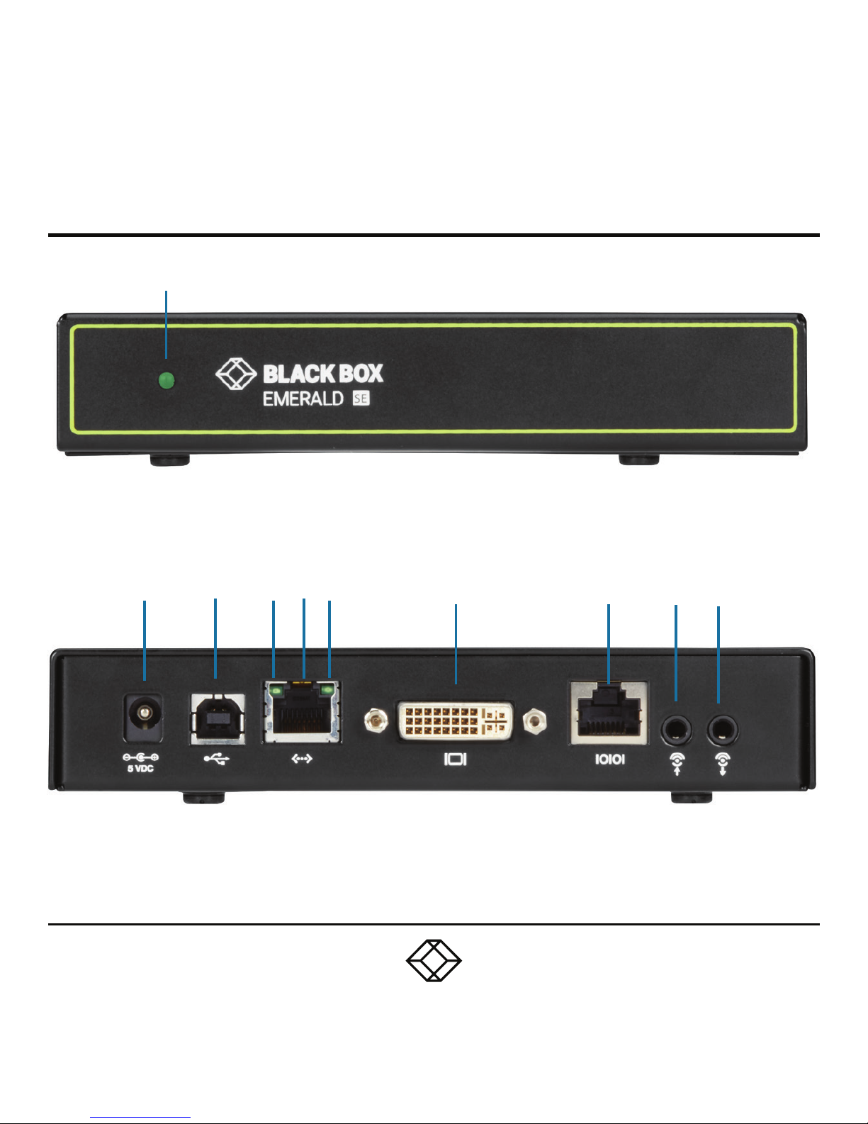
STEP 1A - Transmitter Diagrams
1
2 3 4 5 6 7 8 9 10
Page 3

STEP 1B - Transmitter Components
TABLE 1. EMS2000SE-T COMPONENTS
NUMBER IN DIAGRAM AT LEFT DESCRIPTION DESCRIPTION
1 Power LED button Deactivated, not used
2 5 VDC Power In connector Connect to supplied power adapter
3 USB Type B connector
Connect to PC/workstation USB
connector
4 Speed LED Indicates 10/100/1000 Mbps
5 RJ-45 port Connect to network
6 Activity LED Indicates activity on the link
7 DVI Video connector Connect to PC Video
8 RJ-45 port Connect to serial console
9 Audio Line In Connect to speakers
10 Audio Line Out Connect to speakers
NOTE: Unit automatically powers on when plugged in; must be powered off at the power source.
Page 4

STEP 2A - Receiver Diagrams
2, 3 4 5
1
6 7 8 9 10 11 12
Page 5

STEP 2B - Receiver Components
TABLE 2. EMS2000SE-R COMPONENTS
NUMBER IN DIAGRAM AT LEFT DESCRIPTION DESCRIPTION
1 On/Off button Deactivated, not used
2, 3 (2) USB Type A connectors Connect to USB peripherals
4 Microphone Connect to microphone
5 Speakers Connect to speakers
6 5 VDC Power In connector Connect to supplied power adapter
7 (2) USB Type A connectors Connect to USB peripherals
8 Speed LED Indicates 10/100/1000 Mbps
9 RJ-45 port Connect to network
10 Activity LED Indicates activity on the link
11 DVI Video connector Connect to monitor
12 DB9 connector Connect to serial console
NOTE: Unit automatically powers on when plugged in; must be powered off at the power source.
Page 6

STEP 3 - Connect Power
CONNECT POWER TO TRANSMITTER
1. Locate the power supply adapter and the AC
line cord.
2. Plug the DC connector of the power supply
into the matching socket on the rear of the
transmitter.
3. Attach the AC line cord to the power supply
adapter.
CONNECT POWER TO RECEIVER
1. Locate the power supply adapter and the AC
line cord.
2. Plug the DC connector of the power supply
into the matching socket on the rear of the
receiver.
3. Attach the AC line cord to the power supply
adapter.
CONNECT THE TRANSMITTER
1. Attach the Emerald SE Transmitter to the
target PC/workstation using DVI and USB Type
B cables.
2. Connect to the LAN using standard CAT5
UTP cables between the RJ-45 connector
and the local network connection.
NOTE: The Emerald SE works best with
a 1 Gigabit connection.
CONNECT THE RECEIVER
1. Attach the monitor, keyboard, mouse, USB
and audio devices to the Emerald SE Receiver.
2. Connect to the LAN using standard CAT5
UTP cables between the RJ-45 connector
and the local network connection.
NOTE: The Emerald SE works best with
a 1 Gigabit connection.
STEP 4 - Connect the Peripherals
Page 7

STEP 5 - Starting Up and Default Settings
STARTING UP
1. Once everything is connected, press the
Power button on the front of the Emerald SE
Receiver.
2. The Graphical User Interface (GUI) will
appear on the screen.
3. Enter the default administrator user name
and password.
User name: admin
Password: blank ( just press the Enter key)
4. The default network setting for the Emerald
SE Receiver uses a preconfigured static IP
address.
5. If you require the unit to be set to use DHCP,
select the Control tab on the GUI and then
choose the Network option. Select the DHCP
option and click Apply.
DEFAULT SE TTING S
Default Settings:
Transmitter IP Address: 192.168.1.22
Receiver IP Address: 192.168.1.21
Type: Static
Subnet Mask: 255.255.255.0
Default Gateway: 0.0.0.0
Admin username: admin
Admin password: no password, it is blank by
default
Ports Used: 3389
IMPORTANT: Do not lose the admin password
once configured; there is no way to reset or
retrieve it. The Emerald SE receiver has the
option to create a second administrator account
as a secondary entrance.
Page 8

STEP 6 - Point-to-Point Installation
POINT-TO-POINT INSTALLATION
In a point-to-point configuration, no
administrator setup of the Emerald SE
Transmitter or the Emerald SE receiver is
required. This enables you to install the
system quickly, directly out of the box. In the
point-to-point configuration, you can install
only one transmitter and receiver pair on a
subnet and both must be on the same subnet
unless a router is present in the network
to span subnets. To span across different
subnets, you will need to have admin rights to
both routers on either side of the installation
and setup port forwarding for port “3389”
for Remote Desktop.
If further configuration is required to change
the default IP addresses, you can access
the transmitter’s network settings through
the remote unit:
1. Simply connect the transmitter to the receiver
using a CATx cable (but do not power up the
transmitter yet), then connect a keyboard,
monitor, and mouse to the remote unit (remote
unit is on at this time).
2. Login as “admin” and go to (Control)>>
(Transmitter)>> (Discover) and follow the
on-screen steps.
3. It will advise you to connect both devices
together and then power up the transmitter
and press the “Next” button.
4. It will take several minutes to discover
the transmitter, but once found, you can modify
the network parameters.
Page 9

STEP 7 - Matrix Installation and Getting Started
MATRIX INSTALLATION
In a matrix installation, every Emerald SE
transmitter and receiver requires its own IP
address. By default, the DHCP setting is set
to static, so the addresses will need to be
configured manually:
1. Always configure the transmitter first by
connecting the transmitter to the receiver
using a CATx cable (but do not power up the
transmitter yet), then connect a keyboard,
monitor, and mouse to the remote unit (remote
unit is on at this time).
2. Login as “admin” on the remote unit and
go to (Control)>> (Transmitter)>> (Discover)
and follow the on-screen steps.
3. It will advise you to connect both devices
together, and then power up the transmitter
and press the “Next” button.
4. It will take several minutes to discover the
transmitter, but once found, you can modify
the network parameters.
5. Once the transmitter is configured, you can
now configure the receiver.
6. If the units are on different subnets,
then routers will need to be used to properly
direct traffic.
GETTING STARTED
Once the IP addresses have been configured,
each receiver will need to be configured for
users, user passwords, user access rights
and default video resolutions. You can access
these settings from the receiver’s OSD (reboot
the receiver and login as admin) and begin
configuring these parameters.
NOTE: Each receiver can support a maximum
of 32 users and a maximum of 32 targets
(virtualized or transmitter).
Page 10

STEP X - Name of Step
COPYRIGHT 2018. BLACK BOX CORPORATION. ALL RIGHTS RESERVED.
EMS2000SE_QSG_REV1.PDF
Contact our free, 24/7 technical support in the US at 877-877-2269
or INFO@BLACKBOX.COM
For other countries, go to BLACKBOX.COM/CONTACT-US
 Loading...