

Page 1
INSTALLATION GUIDE
EMD4000-RMK1
EMERALD 4K
RACKMOUNT
TR AY
24/7 TECHNICAL SUPPORT AT 1.877.877.2269 OR VISIT BLACKBOX.CO M
Page 2

NEED HELP?
LEAV E TH E TEC H TO US
LIVE 24/7
TABLE OF CONTENTS
TECHNICAL
SUPPORT
1. 8 7 7. 8 7 7. 2 2 6 9
1. O V E R V I E W ...................................................................................................................................................................................... 3
1.1 Introduction ............................................................................................................................................................................................... 3
1.2 Safety.........................................................................................................................................................................................................3
1.3 What’s Included ........................................................................................................................................................................................ 3
1.4 Rackmount Tray Illustrated .....................................................................................................................................................................3
2. INSTALLATION INSTRUCTIONS .................................................................................................................................................. 4
2.1 Installing the Rackmount Tray ................................................................................................................................................................. 4
2.2 Installing the Transmitter or Receiver .................................................................................................................................................... 6
APPENDIX: DISCLAIMER/TRADEMARKS ....................................................................................................................................... 7
A.1 Disclaimer .................................................................................................................................................................................................7
A.2 Trademarks Used in this Manual ............................................................................................................................................................ 7
2
1. 87 7. 8 7 7. 2 26 9 BL ACK BOX .COM
Page 3
NEED HELP?
LEAV E TH E TEC H TO US
LIVE 24/7
CHAPTER 1: OVERVIEW
TECHNICAL
SUPPORT
1. 8 7 7. 8 7 7. 2 2 6 9
1.1 INTRODUCTION
Use the Emerald 4K Rackmount Tray (EMD4000-RMK1) to mount up to (2) Emerald 4K Transmitter and/or Receiver (EMD4000-T/R) units
in a 2-/4-post 19" rack or cabinet.
1.2 S A FE T Y
WARNING!
Rack loading — Overloading or uneven loading of racks may result in shelf or rack failure, possibly damaging the equipment and
causing personal injury. Stabilize racks in a permanent location before loading begins. Do not exceed your rack’s load rating.
1.3 WHAT’S INCLUDED
The EMD4000-RMK1 contains the following:
Rack Tray (including one blank panel)
Hardware kit – (2) locking brackets, (4) each screw & cage nuts, (2) thumbscrews, (8) M3 x 6mm countersunk screws
Insert Card – How to download your documentation
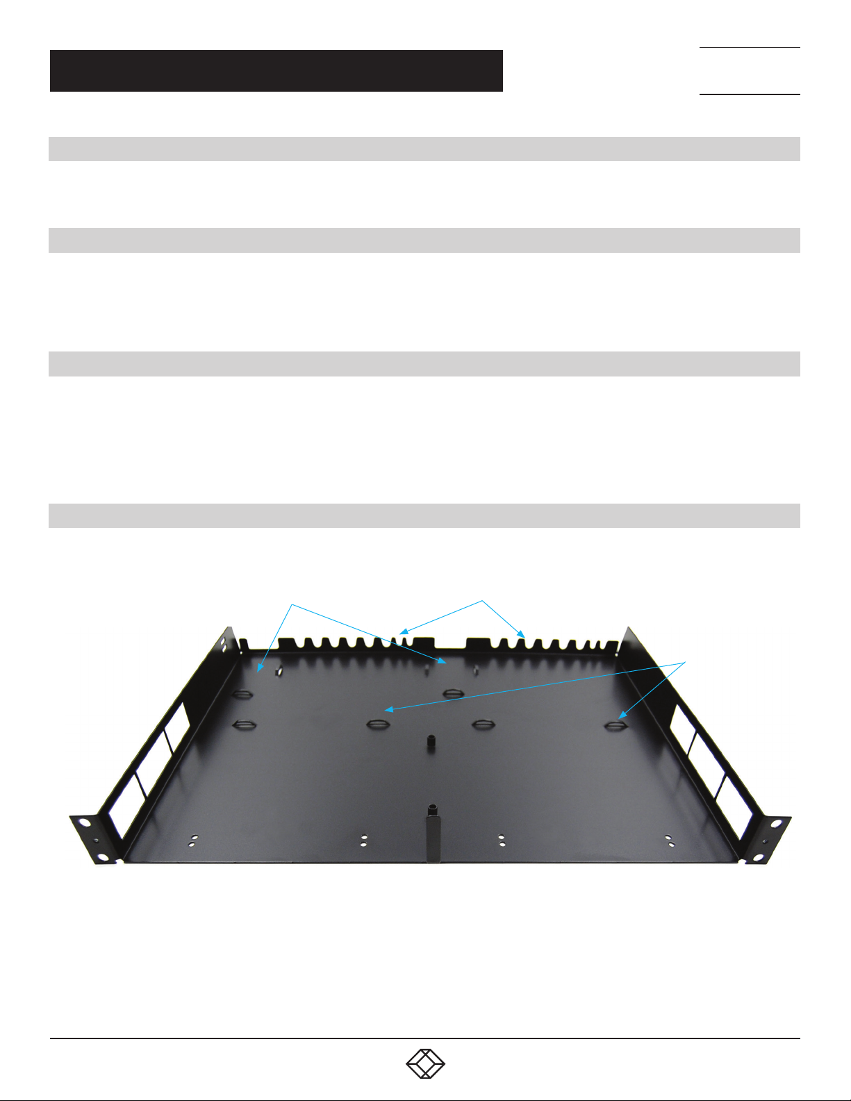
1.4 RACKMOUNT TRAY ILLUSTRATED
Figure 1-1 shows the inside of the rackmount tray.
Power adapter
FIGURE 1-1. INSIDE OF THE RACKMOUNT TR AY
Cable routing
Stop guides
1. 87 7. 8 7 7. 2 26 9 BL ACK BOX .COM
3
Page 4

CHAPTER 2: INSTALLATION INSTRUCTIONS
2.1 INSTALLING THE RACKMOUNT TR AY
Follow the installation instructions listed below in numerical order.
ST E P 1: Remove the rackmount tray from packaging and place it on a secure surface.
STEP 2: Install the cage nuts (supplied) on both sides of the rack. See Figure 2-1.
NEED HELP?
LEAV E TH E TEC H TO US
LIVE 24/7
TECHNICAL
SUPPORT
1. 8 7 7. 8 7 7. 2 2 6 9
FIGURE 2-1. INSTALL THE CAGE NUTS
STEP 3: Attach the tray to the 2-/4-post rack/cabinet from the front. Secure the tray to the rack using two screws for each rack
post. See Figure 2-2.
FIGURE 2-2. ATTACH THE TRAY TO THE RACK
4
1. 87 7. 8 7 7. 2 26 9 BL ACK BOX .COM
Page 5

CHAPTER 2: INSTALLATION INSTRUCTIONS
STEP 4: Tighten all mounting screws to secure the tray in the rack. See Figure 2-3.
NEED HELP?
LEAV E TH E TEC H TO US
LIVE 24/7
TECHNICAL
SUPPORT
1. 8 7 7. 8 7 7. 2 2 6 9
FIGURE 2-3. TIGHTEN THE MOUNTING SCREWS
STEP 5A: Install the locking bracket on the tray using the thumbscrew provided and leave in the “open” position. See Figure 2-4.
FIGURE 2-4. INSTALL THE LOCKING BRACKET
STEP 5B: Repeat for the other side.
1. 87 7. 8 7 7. 2 26 9 BL ACK BOX .COM
5
Page 6

NEED HELP?
LEAV E TH E TEC H TO US
LIVE 24/7
CHAPTER 2: INSTALLATION INSTRUCTIONS
2.2 INSTALLING THE TR ANSMITTER OR RECEIVER
Install one or two Transmitter or Receiver units in the rackmounted dual tray.
STEP 1: Install one Transmitter or Receiver into either slot from the front. The transmitter or receiver is fully inserted when it hits
the stop feature of the dual tray.
NOTE: The blanking panel can be used if only installing one unit and can be secured from underneath using four of the M3 x 6 mm
countersunk screws (included).
STEP 2: If you are installing two Transmitters or Receivers, insert the second one in the open slot.
STEP 3: Lock the installed transmitter or receiver unit into position by “closing” the locking bracket. See Figure 2-5.
TECHNICAL
SUPPORT
1. 8 7 7. 8 7 7. 2 2 6 9
FIGURE 2-5. TRANSMITTERS OR RECEIVERS INSTALLED
NOTE: To remove the Transmitter or Receiver unit, open the locking bracket by unfastening the thumb screw.
STEP 4: If further stability is required, secure from underneath using four of the M3 x 6 mm countersunk screws (included).
6
1. 87 7. 8 7 7. 2 26 9 BL ACK BOX .COM
Page 7

NEED HELP?
LEAV E TH E TEC H TO US
LIVE 24/7
APPENDIX: DISCLAIMER/TRADEMARKS
TECHNICAL
SUPPORT
1. 8 7 7. 8 7 7. 2 2 6 9
A.1 DISCLAIMER
Black Box Corporation shall not be liable for damages of any kind, including, but not limited to, punitive, consequential or cost of
cover damages, resulting from any errors in the product information or specifications set forth in this document and Black Box
Corporation may revise this document at any time without notice.
A.2 TRADEMARKS USED IN THIS MANUAL
Black Box and the Black Box logo type and mark are registered trademarks of Black Box Corporation.
Any other trademarks mentioned in this manual are acknowledged to be the property of the trademark owners.
1. 87 7. 8 7 7. 2 26 9 BL ACK BOX .COM
7
Page 8

NEED HELP?
LEAVE THE TECH TO US
LIVE 24/7
TECHNICAL
SUPPORT
1.87 7. 877. 2 269
© COPYRIGHT 2019. BLACK BOX CORPORATION. ALL RIGHTS RESERVED.
EMD4000-RMK1_INSTALL_REV1.PDF
 Loading...