

Page 1

STEP X - Name of Step
QUICK START GUIDE
EMD4000T, EMD4000R
EMERALD
KVM 4K
24/7 TECHNICAL S UPPOR T AT 877.877.2269 OR VI SIT B LAC KBO X.COM
Page 2
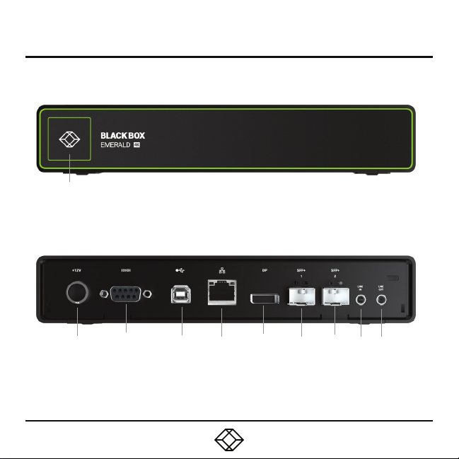
STEP 1A - Transmitter Diagrams
Front panel
1
Back panel
2 3 6
5
4
7
87
9
Page 3

STEP 1B - Transmitter Components
TABLE 1. EMD4000T COMPONENTS
NUMBER IN DIAGRAM AT LEFT DESCRIPTION DESCRIPTION
1 Power LED LED indicates power s tatus
2 12-VDC, 3 -A Power In conne ctor Conne ct to supplie d power adapter
3 DB9 connector Conne cts to serial c onsole port
4 USB Type B connector
5 RJ -45 connector Conne cts to LAN
6 DisplayPort 1.2 video connector C onnect to PC Video
7 (2) SFP+ p orts Dual 10G network por ts
8 Audio Line In Conne ct to PC Line O ut
9 Audio Line Out Connect to PC Line In
Conne ct to PC/workstation USB
connector
Page 4
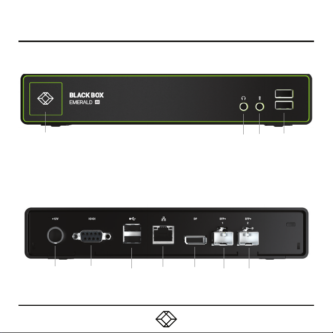
STEP 2A - Receiver Diagrams
Front panel
Back panel
1
10
5
6
7
8
9
3
2
10
4
Page 5

STEP 2B - Receiver Components
TABLE 2. EMD4000R COMPONENTS
NUMBER IN DIAGRAM AT LEFT DESCRIPTION DESCRIPTION
1 On/Of f button
2 Audio LIne Out C onnects to speake rs
3 Audio Microphone In Connects to microphone
4 (2) USB Type A connectors Conne ct to USB peripherals
5 12-VDC, 3 -A Power In conne ctor Connect to supplied power adapter
6 DB9 connector Connects to serial console port
7 (2) USB Type A connectors Conne ct to USB peripherals
8 RJ -45 port Connect to network
9 DisplayPort 1.2 Video connector Connect to monitor
10 (2) SFP+ c onnectors Dual 10G network por ts
Powers on and off unit. LED
indicates power status.
Page 6

STEP 3 - Connect Power
CONNECT POWER TO TRANSMITTER
1. Locate the power supply ad apter and the AC
line cord.
2. Plug the DC connector of the power supply
into the m atching socket on the rear of the
transmitter.
3. Attach the AC lin e cord to the power sup ply
ada pter.
CON NEC T POWER TO RE CEI VER
1. Locate the power supply ad apter and the AC
line cord.
2. Plug the DC connector of the power supply
into the m atching socket on the rear of the
rec eiver.
3. Attach the AC lin e cord to the power sup ply
ada pter.
Page 7

STEP 4 - Connect the Peripherals
CONNECT THE TRANSMITTER
1. Attach t he Emerald Transmitter to the target
PC/workstati on using DisplayPort and USB
Type B cables.
2. Connect the SFP+ transceiver appropriate
for the cable type and distance you are running
over the f iber to the SFP+1.
3. Conn ect from this transceiver to your
10G network switch or directly to a receiver.
Emerald does su pport dire ct attach SFP +,
typically this will be the most cos t efficient
option for a relatively short distance (less than
22.9 feet [7 meters]).
NOTE: SFP+1 must be used as the primary
network connection on the Emerald 4K
Transmitters.
CONNECT THE RECEIVER
1. Attach t he monitor, keyboard, mouse, USB
and audio devices to the Eme rald Receiver.
2. Connect the SFP+ transceiver appropriate
for the fiber cab le type and distance you ar e
runni ng over fiber to SFP +1.
3. Conn ect from this transceiver to your 10G
network switc h or directly to the receive r.
NOTE: SFP+1 must be used as the primary
network connection on the Emerald 4K
Receivers.
Page 8

STEP 5 - Starting Up and Default Settings for IP
STA RT IN G UP
1. Once everyth ing is con nected, press the
Power bu tton on the front of the Emerald
Rec eiver.
2. The On-Screen Display (OSD) will appear on
the screen.
3. Enter the default administrator user name
and password.
4. The default ne twork setting for the Eme rald
Receiver uses a preconf igured static IP
address.
DE FAULT SE TTI NG S
Default Settings:
Transmitter IP Address: 192.168.1.22
Recei ver IP Add ress: 192.168.1.21
Typ e: St atic
Subnet Mask: 255.255.255.0
Default Gateway : 0.0.0.0
Admin username: admin
Admin password: no passwo rd, it is blank by
default
Port s Used: 33 89
IMPORTANT: Do not lo se the admin password
once configured; there is no way to reset or
retrieve it. The Emeral d receiver has the option
to create a second administrator account as a
backup.
Page 9

STEP 6 - Point-to-Point Installation for IP
POINT-TO-POINT INSTALLATION
In a point-to- point configuration, no
administrator setup of the Emerald
Transmit ter or the Emerald receiver is
required. This enable s you to install the
system quickly, directly out of the box. In the
point-to- point configuration , you can install
only on e transmitter and recei ver pair on a
subne t and both must be on the same subnet
unless a router is present in the net work
to span su bnets. To span across d iffere nt
subne ts, you will nee d to have admin rights to
both routers on e ither side of the installation
and setup port forwarding for Po rt 9020, 9030
and 338 9 for KVM; Por t 3389 for RDP for
Remote Desk top.
Page 10

STEP 7 - Matrix Installation and Getting Started for IP
MATRIX INSTALLATION
In an IP installation, every Emerald transmitter
and rec eiver re quires its own IP address.
The network se tting is set to static, so the
addresses will need to be co nfigured manually:
1. Always co nfigure the transmitter first by
connecting the transmitter to the receiver, then
connect a keyboard, monitor, and mouse to the
recei ver unit (receiver is on at this time).
2. Once the transmitte r is configured , you can
now configure the recei ver.
3. A transmitte r out of the b ox must be
configured on the same subnet.
GETTING STARTED
Once th e IP addre sses have been conf igured,
each receiver will need to be configured for
users , user passwords, user access rights
and default video resolutions. You c an access
these settings from the receiver’s OSD (re boot
the receiver and login as admin) and be gin
configuring these parameters.
NOTE: Each rec eiver can support a maximum
of 32 users and a maximum of 32 ta rgets
(virtualized or transmitter).
Page 11

NOTES
Page 12

STEP X - Name of Step
Contact our free, 24/7 technical support in the US at 877-877-2269
or INFO@BLACKBOX.COM
For other countries, go to BLACKBOX.COM/CONTACT-US
COPYRIGHT 2018 BLACK BOX CORPORATION. ALL RIGHTS RESERVED.
EMD4000T_EMD4000R_QSG_REV1.PDF
 Loading...