

Page 1
USER MANUAL
EMERALD
EMERALD
EMD2000SE-T, EMD2000SE-R, EMD2002SE-T, EMD2002SE-R
EMERALD SE
KVM OVER IP
TECHNOLOGY
24/7 TECHNICAL SUPPORT AT 1.877.877.2269 OR VISIT BLACKBOX.COM
Page 2

NEED HELP?
LEAV E TH E TEC H TO US
LIVE 24/7
TABLE OF CONTENTS
TECHNICAL
SUPPORT
1. 8 7 7. 8 7 7. 2 2 69
1. SPECIFICATIONS ........................................................................................................................................................................... 5
1.1 General Specifications ............................................................................................................................................................................. 5
1.2 What’s Included in the Kits ...................................................................................................................................................................... 6
1.3 Licensing ...................................................................................................................................................................................................7
2. OVERVIE W ...................................................................................................................................................................................... 8
2.1 Emerald SE System Features .................................................................................................................................................................. 8
2.2 Overview of Emerald SE Devices ............................................................................................................................................................ 9
2.2.1 Video ................................................................................................................................................................................................................... 10
2.2.2 Audio ................................................................................................................................................................................................................... 10
2.2.3 Support for Keyboards, Mice, and USB Devices .......................................................................................................................................10
2.2.4 IP Addressing ....................................................................................................................................................................................................10
2.2.5 Firmware Upgrade ........................................................................................................................................................................................... 11
2.3 Application Examples ............................................................................................................................................................................ 11
2.3.1 Video, Audio and USB Extension ..................................................................................................................................................................11
2.3.2 Video, Audio and USB Switching .................................................................................................................................................................. 12
3. CONFIGURATION ........................................................................................................................................................................ 13
3.1 Configuration of Receiver ...................................................................................................................................................................... 13
3.2 Configuration of Transmitter ................................................................................................................................................................13
3.3 Configuration of Boxilla ......................................................................................................................................................................... 14
4. MODES OF OPERATION .............................................................................................................................................................. 15
4.1 Auto Login ............................................................................................................................................................................................... 15
4.2 Auto Connect .......................................................................................................................................................................................... 15
4.3 Private Connection .................................................................................................................................................................................15
4.4 Shared Connection ................................................................................................................................................................................15
5. INSTALLATION ............................................................................................................................................................................ 16
5.1 Emerald SE Receiver (EMD2000SE-R, EMD2002SE-R) Checklist ........................................................................................................ 16
5.2 Emerald SE Transmitter (EMD2000SE-T, EMD2002SE-T) Checklist.....................................................................................................16
5.3 Emerald SE Transmitter Kit (EMD2000SE-T-K, EMD2002SE-T-K) Checklist ........................................................................................ 16
5.4 Installation Options ............................................................................................................................................................................................ 16
5.5 Connect the Emerald SE Receiver.................................................................................................................................................................... 17
5.6 Connect the Emerald SE Transmitter .............................................................................................................................................................. 20
6. NETWORKED INSTALLATION .................................................................................................................................................... 22
6.1 Point-to-Point Installation ......................................................................................................................................................................22
6.2 Unmanaged or Managed Matrix Installation .......................................................................................................................................22
2
1. 8 7 7. 8 7 7. 2 2 6 9 BLACKBOX.COM
Page 3

NEED HELP?
LEAV E TH E TEC H TO US
LIVE 24/7
TABLE OF CONTENTS
TECHNICAL
SUPPORT
1. 8 7 7. 8 7 7. 2 2 69
7. OPERATION OF EMERALD SE SYSTEM ..................................................................................................................................... 23
7.1 LED Identification ...................................................................................................................................................................................23
7.2 Accessing the System ........................................................................................................................................................................... 23
8. OSD FUNCTIONS ......................................................................................................................................................................... 24
8.1 User Types ............................................................................................................................................................................................... 24
8.2 Log On ..................................................................................................................................................................................................... 24
8.3 Default Username and Password .........................................................................................................................................................25
8.4 User Views and Capabilities .................................................................................................................................................................. 26
8.5 Connections Screen ...............................................................................................................................................................................26
8.5.1 Creating a New Connection ...........................................................................................................................................................................27
8.5.2 Connection Favorites ......................................................................................................................................................................................28
8.5.3 Connecting ........................................................................................................................................................................................................29
8.5.4 Edit Connection ................................................................................................................................................................................................29
8.5.5 Remove Connection ........................................................................................................................................................................................29
8.6 Control Tab ..............................................................................................................................................................................................30
8.6.1 Preferences ........................................................................................................................................................................................................31
8.6.2 Network ..............................................................................................................................................................................................................34
8.6.3 System ...............................................................................................................................................................................................................35
8.7 Managing Users .....................................................................................................................................................................................43
8.7.1 Add a User ..........................................................................................................................................................................................................44
8.7.2 Auto Log-on .......................................................................................................................................................................................................44
8.7.3 Edit a User ..........................................................................................................................................................................................................46
8.7.4 Remove a User ..................................................................................................................................................................................................47
APPENDIX A. EMERALD SE VIDEO RESOLUTIONS SUPPORTED ...............................................................................................48
APPENDIX B. CONFIGURING WINDOWS 7 VIRTUAL MACHINES FOR EMERALD SE ............................................................... 49
APPENDIX C. EMER ALD SE NETWORK PROTOCOLS OVERVIEW .............................................................................................. 50
1. 8 7 7. 8 7 7. 2 2 6 9 BLACKBOX.COM
3
Page 4

NEED HELP?
LEAV E TH E TEC H TO US
LIVE 24/7
TABLE OF CONTENTS
APPENDIX D. TROUBLESHOOTING ............................................................................................................................................... 51
APPENDIX E. REGULATORY INFORMATION ................................................................................................................................ 53
E.1 FCC Statement .......................................................................................................................................................................................53
E.2 NOM Statement......................................................................................................................................................................................54
APPENDIX F. DISCLAIMER/TRADEMARKS .................................................................................................................................. 55
F.1 Disclaimer ............................................................................................................ ....................................................................................55
F.2 Trademarks Used in this Manual ...........................................................................................................................................................55
TECHNICAL
SUPPORT
1. 8 7 7. 8 7 7. 2 2 69
4
1. 8 7 7. 8 7 7. 2 2 6 9 BLACKBOX.COM
Page 5

NEED HELP?
LEAV E TH E TEC H TO US
LIVE 24/7
CHAPTER 1: SPECIFICATIONS
TECHNICAL
SUPPORT
1. 8 7 7. 8 7 7. 2 2 69
1.1 GENERAL SPECIFICATIONS
TABLE 1-1. SPECIFICATIONS
SPECIFICATION DESCRIPTION
Approvals
Unit FCC, CE, CSA, RoHS, WEEE
Power Supply TU V, UL
Physical
(1) Power LED button (deactivated, not used);
NOTE: Unit automatically powers on when plugged in; must be powered off at the power source.
(1) RJ-45 Speed LED (green, located on top left of RJ-45 connector):
Blinks three times when the network connection is 1000 Mbps,
Blinks two times when network connection is 100 Mbps,
LED Interface
Maximum Distance from CPU
to Transmitter
Maximum Distance between
Transmitter and Receiver
Operating System Support
Connectors
Dimensions
Weight
Operation
Default IP Address
Encryption Secure Sockets Layer (SSL) over TCP/IP, 128-bit between TX and RX, user set between RX and Hyper-V
Default Username admin
Default Password The password is blank by default
DDC Support Built-in/clone of remote
Switching Time <1 sec
Blinks once when the network connection is 10 Mbps,
Not blinking: No Link to network;
(1) Activity LED (green, located on top right of RJ-45 connector):
Solid green: Link up,
Blinking: Activity on the link,
OFF: No link
EMD2000SE-T: 16 ft. (5 m), DVI-D and USB limitations
328 ft. (100 m), use a network switch to get farther distances
®
Microsoft Windows
Solaris, Mac OS
EMD2000SE-T: (1) DVI input, (1) USB Type B female, (1) RJ-45 network, (1) RJ-45 serial, (2) 3.5 mm audio,
(1) 2.5 mm barrel for power;
EMD2000SE-R: (1) DVI output, (4) USB Type A female, (1) RJ-45 network, (1) DB9 serial,
(2) 3.5 mm audio for SPK and MIC, (1) 2.5 mm barrel for power;
EMD2002SE-T: (2) DVI input, (1) USB Type B female, (1) RJ-45 network, (1) RJ-45 serial, (2) 3.5 mm audio,
(1) 2.5 mm barrel for power;
EMD2002SE-R: (2) DVI output, (4) USB Type A female, (1) RJ-45 network, (1) DB9 serial,
(2) 3.5 mm audio for SPK and MIC, (1) 2.5 mm barrel for power
EMD2000SE-T, EMD2000SE-R: 1.15" H x 6.2" W x 4.2" D (2.92 x 15.75 x 10.67 cm);
EMD2002SE-T: 1.43” H x 6.2” W x 4.2” D (3.65 x 15.75 x 10.67 cm);
EMD2002SE-R: 1.15” H x 6.2” W x 4.2” D (2.92 x 15.75 x 10.67 cm)
EMD2000SE-T, EMD2000SE-R: 1.18 lbs (0.54 kg);
EMD2002SE-T: 1.47 lb. (0.67 kg);
EMD2002SE-R: 1.36 lb. (0.62 kg)
EMD2000SE-T, EMD2002SE-T: 192.168.1.22;
EMD2000SE-R, EMD2002SE-R: 192.168.1.21
Vista, XP, Windows 7, Windows 8, Windows 10, Server 2003, Server 2008, Server 2012, LInux®,
1. 8 7 7. 8 7 7. 2 2 6 9 BLACKBOX.COM
5
Page 6

CHAPTER 1: SPECIFICATIONS
TABLE 1-1 (CONTINUED). SPECIFICATIONS
SPECIFICATION DESCRIPTION
Power
Power Source External in-line power supply
Input Voltage 100–240 VAC, 50/60 Hz
Input Current 0.9 amps maximum
Power Consumption
Heat Dissipation
Output Connector 2.5-mm barrel
Input Connector IEC-320, C8
Power Supply Cord Length 6 ft. (1.8 m)
Environmental
Operating Temperature 32 to 104° F (0 to 40° C)
Storage Temperature -4 to +140° F (-20 to 60° C)
Operating Humidity 5 to 95%, noncondensing
Unit: 6.5 watts with keyboard and mouse attached;
Power supply is 20 W to support USB based powered devices
(5 VDC x 4 amps) x 3.41 = 68.2 BTU/hour maximum
(Voltage x Nominal Current) x 3.41 = BTU/hr
NEED HELP?
LEAV E TH E TEC H TO US
LIVE 24/7
TECHNICAL
SUPPORT
1. 8 7 7. 8 7 7. 2 2 69
1.2 WHAT’S INCLUDED IN THE KITS
NOTE: Does not include local CPU cables, order separately.
EMD2000SE-T includes:
(1) Emerald SE Transmitter, Single-Head
(1) 5 VDC Power Supply
(1) US Power Cord
(4) rubber feet
EMD2000SE-R includes:
(1) Emerald SE Receiver, Single-Head
(1) 5 VDC Power Supply
(1) US Power Cord
(4) rubber feet
EMD2002SE-T includes:
(1) Emerald SE Transmitter, Dual-Head
(1) 5 VDC Power Supply
(1) US Power Cord
(4) rubber feet
EMD2002SE-R includes:
(1) Emerald SE Receiver, Dual-Head
(1) 5 VDC Power Supply
(1) US Power Cord
(4) rubber feet
6
1. 8 7 7. 8 7 7. 2 2 6 9 BLACKBOX.COM
Page 7

CHAPTER 1: SPECIFICATIONS
NEED HELP?
LEAV E TH E TEC H TO US
LIVE 24/7
TECHNICAL
SUPPORT
1. 8 7 7. 8 7 7. 2 2 69
EMD2000SE-T-K includes:
(1) Emerald SE Transmitter, Single-Head
(1) 5 VDC Power Supply
(1) US Power Cord
(4) rubber feet
(1) EHN900025U-0006
(1) USB05E-0006
(1) EJ110-0005
EMD2000SE-K includes:
(1) EMD2000SE-T-K
(1) EMD2000SE-R
EMD2002SE-T-K includes:
(1) Emerald SE Transmitter, Dual-Head
(1) 5 VDC Power Supply
(1) US Power Cord
(4) rubber feet
(2) EHN900025U-0006
(1) USB05E-0006
(1) EJ110-0005
EMD2002SE-K includes:
(1) EMD2002SE-T-K
(1) EMD2002SE-R
1.3 LICENSING
There are 2 options for managing Emerald SE Transmitters and Receivers:
Option 1 (for small unmanaged matrices): Using built in receiver manager
Option 2 (for large managed matrices): Using Boxilla BXAMGR
NOTE: For managed installations with more than 32 users, you will need to use Boxilla KVM AV/IT Manager. The basic Boxilla
license (BXAMGR) supports 25 users.
Other available licenses for Boxilla are listed below:
50 Users, Devices or Connections (BXAMGR-50)
100 Users, Devices or Connections (BXAMGR-100)
200 Users, Devices or Connections (BXAMGR-200)
300 Users, Devices or Connections (BXAMGR-300)
Unlimited Users, Devices or Connections (BXAMGR-ULT)
Available upgrade licenses for Boxilla are listed below:
Add 25 Users, Devices or Connections (BXAMGR-LIC-25)
Add 100 Users, Devices or Connections (BXAMGR-LIC-100)
Add Unlimited Users, Devices or Connections (BXAMGR-LIC-ULT)
1. 8 7 7. 8 7 7. 2 2 6 9 BLACKBOX.COM
7
Page 8
NEED HELP?
LEAV E TH E TEC H TO US
LIVE 24/7
CHAPTER 2: OVERVIEW
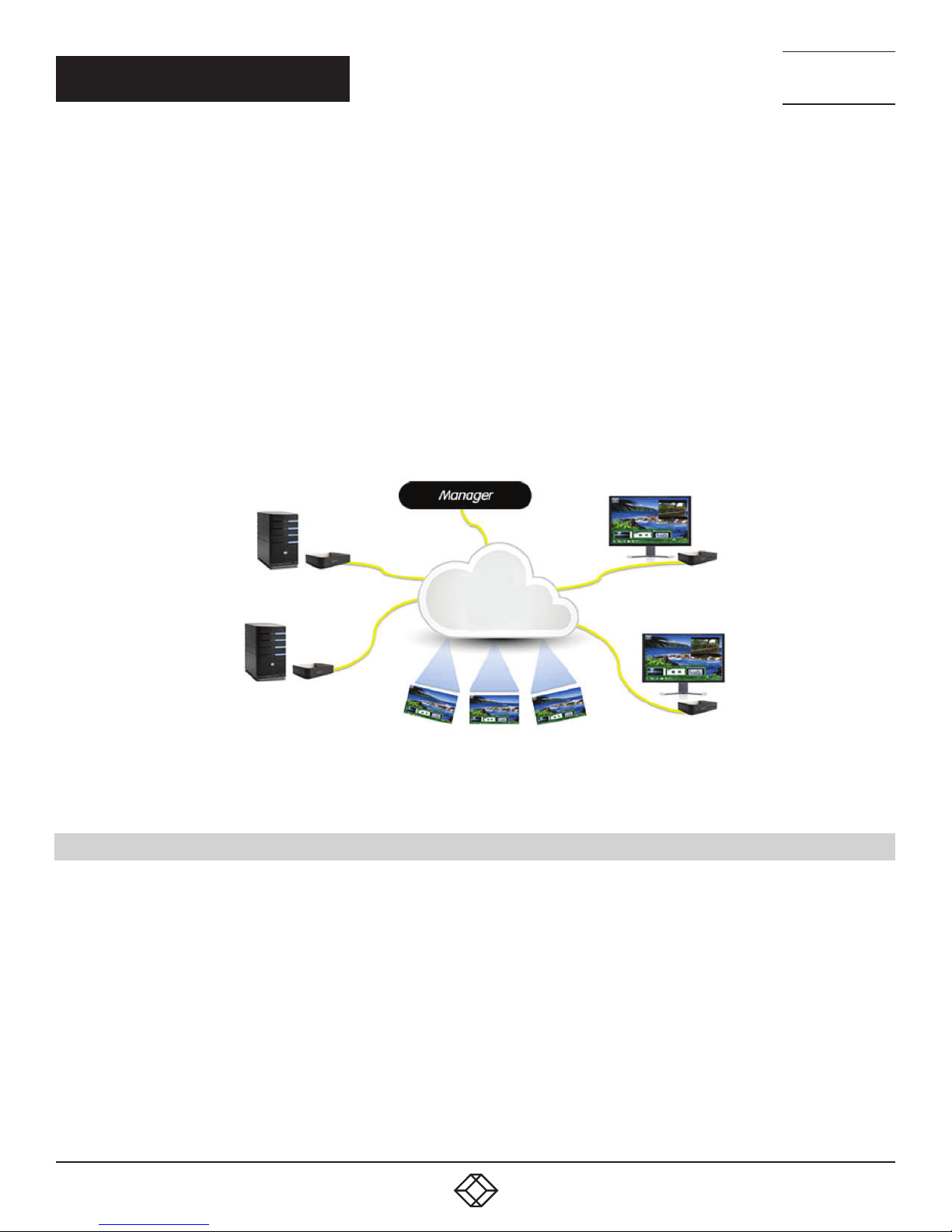
The Emerald SE system provides users with a seamless desktop experience anywhere on a TCP/IP network, while allowing the actual
hardware to be securely housed in a corporate data center or in the cloud. Emerald SE enables the same high fidelity experience of a
desktop PC even for media-rich applications, for example, watching videos, photo editing with Photoshop or 3D design with AutoCAD.
The remote desktops may be hosted on a physical PC / workstation or may be a virtual desktop hosted on a private server or in the
cloud. The Emerald SE system provides its users with Receivers that communicate with target computer nodes (whether physical PC
or virtual desktop) over a standard TCP/IP network. Physical PCs/Workstations/Servers have an Emerald SE Transmitter unit
physically connected to provide communication over the TCP/IP network. The performance of Emerald SE allows them to be deployed
on standard corporate networks and even across Wide-Area-Networks (WANs).
Desktop users can access remote keyboard, mouse, video, audio, USB mass storage devices, headsets and other USB devices from
the Receiver unit to the remote PC/workstations or Virtual Desktop via the Emerald SE system.
NOTE: Some USB 2.0 devices have been found to be incompatible. Please report these devices to Black Box.
NOTE: References to the Emerald SE system in this document refer to both Receivers (EMD2000SE-R, EMD2002SE-R) and
Transmitters (EMD2000SE-T, EMD2002SE-T).
TECHNICAL
SUPPORT
1. 8 7 7. 8 7 7. 2 2 69
Transmitters
Receivers
Virtual Desktops
FIGURE 2-1. EMERALD SE EX AMPLE—INCLUDING PHYSICAL AND VIRTUAL DESKTOPS
2.1 EMERALD SE SYSTEM FEATURES
Emerald SE leverages state-of-the-art technologies in compression, networking, and latency management. Some of the key
features of Emerald SE are:
Pixel-Perfect Video Quality: The Emerald SE system uses a compound compression algorithm to provide a lossless video
experience at a low network bandwidth. None of the bandwidth variability and noise effects of analog extension schemes exist.
Emerald SE can support a 1080p HD movie in <40 Mbps.
Uses M/C stream for shared mode to allow scaling of # of users that can share a transmitter. Analog audio can now be shared in a
shared mode connection.
Seamless integration of Physical and Virtual Desktops: The Emerald SE system connects to physical PCs, servers, and video
sources as well as virtual desktops hosted on servers or in the cloud. This allows seamless connection to physical resources and
virtual resources from the same Receiver unit. IT professionals use this capability to optimize their deployments and migrations to
cloud services.
8
1. 8 7 7. 8 7 7. 2 2 6 9 BLACKBOX.COM
Page 9

NEED HELP?
LEAV E TH E TEC H TO US
LIVE 24/7
CHAPTER 2: OVERVIEW
TECHNICAL
SUPPORT
1. 8 7 7. 8 7 7. 2 2 69
High Reliability and Highly Secure: The Emerald SE system minimizes maintenance for administrators. The intuitive On-Screen-
Display is simple to learn and understand. The individual units have no moving parts to minimize potential for hardware failures. All
media streams transmitted between the Emerald SE devices are encrypted using 128-bit SSL. Password protection is also provided
to control access to all administration functions.
Transparent USB Re-Direction: The Emerald SE system provides transparent USB re-direction for both virtual and physical
desktop connections. Keyboards and mice are collated to a common channel while other USB devices are re-directed to virtual or
physical targets. There is a limit of two non-keyboard/mice devices that can be re-directed to a Transmitter unit (i.e. physical PC/
Workstation)
Environmentally Optimized: The Emerald SE system is optimized to minimize power requirements and eliminate noise. All Receivers
and Transmitters consume less than 6 Watts and are completely silent.
Easy Deployment: The Emerald SE system is designed to be easily and quickly deployed. No new drivers or software need to be
installed on target PCs or Virtual Desktops. The system uses standard networking protocols and cabling. Users and connections
are defined using an intuitive On-Screen-Display (OSD). Connections can be made via simple “click on target.” Multiple modes
of operation such as private connections, shared connections, auto-login, and auto-connect enable various workflows and
collaborations to be supported. Analog audio can now be shared in a shared mode connection.
2.2 OVERVIEW OF EMERALD SE DEVICES
The Emerald SE family is composed of two Receivers, two Transmitters, and a Boxilla Managers.
TABLE 2-1. EMERALD SE MODELS
RECEIVER NUMBER OF VIDEO HEADS USB PORTS SERIAL AUDIO DVI CPU CABLE USB CPU CABLE
EMD2000SE-R (1) DVI (4) USB 2.0 Type A Yes Yes Not applicable Not applicable
EMD2002SE-R (2) DVI (4) USB 2.0 Type A No Yes Not applicable Not applicable
TRANSMITTER NUMBER OF VIDEO HE ADS USB PORTS SERIAL AUDIO DVI CPU CABLE USB CPU CABLE
EMD2000SE-T (1) DV I (1) USB 2.0 Type B Yes Yes Not included Not included
EMD2002SE-T (2) DVI (1) USB 2.0 Type B No Yes Not included Not included
MANAGER NUMBER OF VIDEO HEADS USB PORTS SERIAL AUDIO DVI CPU CABLE USB CPU CABLE
BXAMGR (1) DVI (4) USB 2.0 Type A Yes Yes Not applicable Not applicable
Some of the key capabilities and operation of Emerald SE devices are described next. These capabilities are supported across all
Emerald SE devices.
1. 8 7 7. 8 7 7. 2 2 6 9 BLACKBOX.COM
9
Page 10

NEED HELP?
LEAV E TH E TEC H TO US
LIVE 24/7
CHAPTER 2: OVERVIEW
TECHNICAL
SUPPORT
1. 8 7 7. 8 7 7. 2 2 69
2.2.1 VIDEO
The Emerald SE system supports 24-bit color depth digital video up to a maximum resolution of 1920 x 1200 at 60 Hz for any
video head on both Transmitter and Receiver. One or two DVI-I connectors is provided on the Receiver or Transmitter for cable
compatibility, but only digital video is supported. One DVI-I connector is provided on the Boxilla Manager. See Appendix 1 - Emerald
SE Video Resolutions Supported for the list of resolutions currently supported by Emerald SE. VGA or Analog video can be
supported by using the KVGA-DVID VGA to DVI-D converter.
2.2.2 AUDIO
The Emerald SE system supports CD-quality stereo audio from the remote workstation (with the Transmitter connected) or virtual
desktop to peripheral speakers connected to the USB connector on the Emerald SE Receiver. The Emerald SE Transmitter uses its
USB interface to capture audio from the remote workstation. This increases audio quality by eliminating analog audio noise issues
and removing the need for a sound card in PC/Workstation.
The Emerald SE Receiver connects audio from a peripheral microphone connected via the USB connector on the Receiver to
the remote workstation or a virtual desktop. The Emerald SE Transmitter uses USB to supply the microphone data to the remote
workstation. Higher quality audio can be obtained using USB re-direction for USB headsets or speakers.
2.2.3 SUPPORT FOR KEYBOARDS, MICE AND USB DEVICES
USB keyboards and mice are fully supported by the Emerald SE system. Composite mouse and keyboard devices are supported,
along with other types of USB devices such as Flash/Thumb Drives, CD and DVD/ROM drives, printers, pen tablets, touch-panels,
and isochronous USB devices such as headsets.
Support for non-keyboard and mice devices is provided on an Emerald SE Receiver using USB re-direction. This capability can
be enabled or disabled by the administrator. In an Emerald SE Receiver, the first two devices that are not keyboard or mouse are
assigned to the USB re-direction channel automatically and passed to the remote computer when connected via a Transmitter.
When connecting to a non-Transmitter target (i.e. virtual desktop), up to eight USB devices can be re-directed.
NOTE: A hub can be attached externally to an Emerald SE Receiver, but a maximum of two devices can be assigned to USB
re-direction on connections to Transmitters. Multiple keyboard and mice can additionally be supported—though all use the default
drivers on the target PC.
2.2.4 IP ADDRESSING
The Emerald SE devices are IP-addressable, giving you the flexibility to locate workstations anywhere within your enterprise and
at any distance from your desktop users. The Emerald SE devices use standard network protocols to transfer data between the
remote Workstation/Virtual Desktop and the peripheral devices located at the user’s desk. The Emerald SE system can operate on
a network connection of 100 Mbps or 1 Gbps.
The receiver can be configured using a static or DHCP assigned IP address while the transmitter requires a static IP address only.
10
1. 8 7 7. 8 7 7. 2 2 6 9 BLACKBOX.COM
Page 11

NEED HELP?
LEAV E TH E TEC H TO US
LIVE 24/7
CHAPTER 2: OVERVIEW
TECHNICAL
SUPPORT
1. 8 7 7. 8 7 7. 2 2 69
2.2.5 FIRMWARE UPGRADE
Upgrade your firmware at any time using an Emerald SE manager or using a USB flash-drive in an Emerald SE Receiver unit to
ensure that your Emerald SE system is always running the most current version available. The Emerald SE devices —Receiver and
Transmitter—are upgradable.
2.3 APPLICATION EXAMPLES
The Emerald SE system is built to be flexible so that it can be deployed in many different types of applications such as basic
extension, switching applications (sometimes called matrix), cloud-based desktops, control rooms, digital signage, and kiosk
applications and other applications in banking, financial services, broadcast, network operations, industrial, government and
enterprise computing sectors. Emerald SE provides the state-of-the art performance by:
using digital sources for video and audio, hence removing analog noise issues or other potential environmental issues
using advanced optimized compression to enable visually lossless video over standard low-bandwidth networks rather than a
proprietary connection or dedicated gigabit networks of many systems
2.3.1 VIDEO, AUDIO AND USB EXTENSION
Many applications require Video, Audio, or USB extension (or all three together) such as PC back-racking, board-room fit-out,
remote monitoring, and digital signage.
The Emerald SE system is set up to connect the Transmitter to the Receiver straight out of the box on a point-to-point network.
The Transmitter and Receiver can be attached to standard Ethernet IP networks to increase the distance between units – within
a building, between buildings, or across a country. Only standard Ethernet/IP rules and the maximum latency the application can
tolerate need to be considered. If video and/or audio extension only is being used, latency rarely is a consideration as the traffic
is typically one-way. When USB-based peripheral devices are also required a network latency of <50 ms is recommended to avoid
user issues with “poor mouse response”, etc. For some applications, such as graphic design network latency ,<20 ms may be
required to ensure user satisfaction. Latency normally is only an issue when extending across a WAN, because latency inside
modern buildings or on dedicated networks are much less than 1 ms.
NOTE: Emerald SE supports latency of <20 ms.
In Figure 7-1, a typical deployment is shown in a basic extender application. In this deployment, only one Transmitter and Receiver
are used to allow remote access to a single workstation.
1. 8 7 7. 8 7 7. 2 2 6 9 BLACKBOX.COM
11
Page 12
CHAPTER 2: OVERVIEW
TRANSMITTER
NEED HELP?
LEAV E TH E TEC H TO US
LIVE 24/7
TECHNICAL
SUPPORT
1. 8 7 7. 8 7 7. 2 2 69
WORKSTATION
HOST COMPUTER
RECEIVER
FIGURE 7-1. BASIC EXTENDER APPLICATION
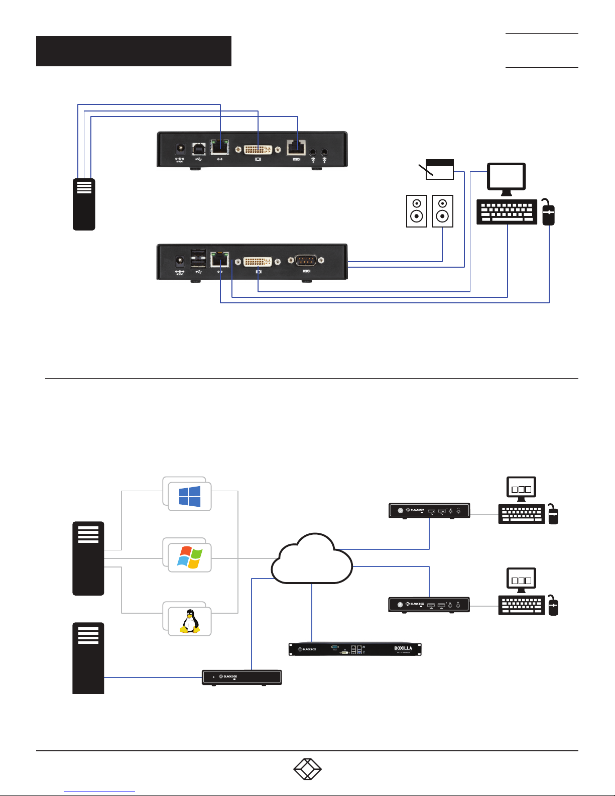
2.3.2 VIDEO, AUDIO AND USB SWITCHING
Numerous applications require being able to switch between different target PCs or Virtual Desktops. The user wants to be able
to change the source of Video, Audio, or USB extension (or all three together).
Connections can be made to a target using Emerald SE’s intuitive On-Screen-Display (OSD). In Figure 7-2, a larger scale system
is shown. This is referred to as a switching or matrix type of deployment. In this deployment, there are several Receivers and
Transmitters and a manager, as well as virtual desktops.
SE
KVM OVER RDP/REMOTE FX
OR PCoIP
EMERALD
EMERALD
RECEIVER 1
VIRTUAL DESKTOPS
EMERALD TRANSMITTER
12
IP, INTERNET
OR PROPRIETARY
KVM NETWORK
EMERALD RECEIVER 2
BOXILLA KVM MANAGER
SE
EMERALD
FIGURE 7-2. EMERALD SE SWITCHING EX AMPLE
1. 8 7 7. 8 7 7. 2 2 6 9 BLACKBOX.COM
EMERALD
SE
Page 13

NEED HELP?
LEAV E TH E TEC H TO US
LIVE 24/7
CHAPTER 3: CONFIGURATION
3.1 CONFIGURATION OF RECEIVER
An Emerald SE Receiver connects to a physical PC or a virtual desktop over a TCP/IP network and decrypts and decompresses
the streams to provide video, audio, and USB connections to a user. The user is presented with typical PC connections—video out
(typically DVI), USB (typically 4 ports of USB 2.0), line out, and microphone in (see individual Receiver’s data-sheets for specific
ports provided).
The Transmitter-Receiver connection uses Black Box’s compound compression algorithm for video called Dynamic Content
Optimized Compression (DCOC). This algorithm optimizes compression based on content in the video stream and on available
network bandwidth. Standard Microsoft RDP is used for connections to Virtual Desktops. Multiple versions of RDP are supported
from RDP 8.1 to legacy versions. This allows Emerald SE Receivers to connect to Microsoft Hyper-V, VMWare ESX, and Citrix XEN
based virtual desktops as well as session host based desktops (previously called Terminal Services).
The Receiver is configured using an On-Screen Display (OSD) built into the Receiver or using the Boxilla Manager. The network
settings and unit name among others can be configured for a Receiver. The target connections are defined by their target name
or IP address, log-in username/password, and TCP port number to be used. Users can be created and specific connections may be
allocated to the different users.
A Receiver user profile is protected by username and password to permit different users to access the same unit securely.
Multiplatform support
Emerald SE is compatible with the following operating systems:
Microsoft
Systems (e.g., 2003, Server 2008, Server 2012)
Linux
Solaris
Mac OS
The default keyboard drivers for these operating systems are supported by the Emerald SE system.
NOTE: For virtual desktops, typically Pro or Enterprise versions of the Windows operating system are required for VDI to support
®
Windows Desktop Operating Systems (e.g. Windows 7, Windows 8, Windows 10) and Microsoft Server Operating
®
®
®
RemoteFX™. See www.microsoft.com for Terminal Services (RDSH) or VDI (RDVH) requirements.
TECHNICAL
SUPPORT
1. 8 7 7. 8 7 7. 2 2 69
3.2 CONFIGURATION OF TRANSMITTER
An Emerald SE Transmitter converts the video, audio, and USB connections of a PC or Workstation to a format that can be
connected and controlled over a TCP/IP network. The Transmitter connects to the DVI and USB ports of a PC or workstation. The
Transmitter controls the connection to a remote Receiver and manages the flow of information to it. It converts and compresses
video and audio information for transmission over standard TCP/IP networks, along with USB peripheral communications. All data
communication uses 128-bit encryption.
The Transmitter uses Black Box’s compound compression algorithm for video called Dynamic Content Optimized Compression
(DCOC). This algorithm optimizes compression and latency on a frame-by-frame basis, depending on content in the video stream
and on available network bandwidth. This enables an optimal user experience in challenging network environments.
The Transmitter is configured from an Emerald SE Receiver or Boxilla Manager. The network settings, unit name, and video quality
are among the parameters that can be configured on a Transmitter.
Multiplatform support
The Transmitter is connected to the remote workstation via USB and DVI connectors. This enables the Emerald SE Receiver to
interoperate seamlessly with Windows, Linux
®
, and Macintosh© workstations/servers.
1. 8 7 7. 8 7 7. 2 2 6 9 BLACKBOX.COM
13
Page 14

NEED HELP?
LEAV E TH E TEC H TO US
LIVE 24/7
CHAPTER 3: CONFIGURATION
3.3 CONFIGURATION OF BOXILLA MANAGER
In a basic installation, you can configure Emerald via an Emerald receiver’s built-in OSD display. For larger installations, a Boxilla
Manager (BXAMGR) can manage a network of Emerald Receivers and Transmitters. The BXAMGR can manage 25 transmitters/
receivers by default. It can manage an unlimited number of Emerald transmitters/receivers when using an upgrade license.
A Boxilla user profile is protected by username and password to permit different users to access the same unit securely. It
maintains the central database that is distributed to all Receivers in the “domain” of the Boxilla (i.e. discovered and added to
manager) – called the “managed domain”. This distribution ensures that there is no single point of failure in the Emerald system –
each Receiver has a copy of the database. This enables each Receiver to continue operation – log users in, make connections as
required – even if the Boxilla goes off-line.
Using the intuitive Boxilla web-based interface, one or more administrators can manage potentially thousands of users who are
interacting with an almost unlimited number of devices. Boxilla operates as a self-contained compact server unit that can be
located anywhere within your network. Boxilla is supplied pre-loaded and is straightforward to deploy, requiring only a network
connection and a power input to begin operation.
The current version of Boxilla provides management of Black Box’s Emerald SE system. For more information on Boxilla, refer to
the Boxilla user manual.
TECHNICAL
SUPPORT
1. 8 7 7. 8 7 7. 2 2 69
14
1. 8 7 7. 8 7 7. 2 2 6 9 BLACKBOX.COM
Page 15

NEED HELP?
LEAV E TH E TEC H TO US
LIVE 24/7
CHAPTER 4: MODES OF OPERATION
TECHNICAL
SUPPORT
1. 8 7 7. 8 7 7. 2 2 69
The Emerald SE system has various modes of operation such as Auto-Login, Auto-Connect, Private Connection, and Shared
Connection Modes.
4.1 AUTO LOGIN
In Auto-Login Mode, turning on the Emerald SE Receiver automatically causes a login as a pre-defined user. The user is presented
with the permitted connections that have been predefined.
4.2 AUTO CONNECT
In Auto-Connect Mode, when a user logs-in to the Emerald SE Receiver, it causes an automatic connection to their pre-allocated
workstation or virtual desktop. Auto-Login and Auto-Connect are defined independent of each other, but can be used together to
auto login/auto connect devices that are difficult to reach.
4.3 PRIVATE CONNECTION
In Private Connection Mode, when a user makes a connection to a target workstation/virtual desktop, this connection is only
accessible by this user. All other users will receive a “busy” message if they attempt to connect to the same workstation/virtual
machine. This is the default mode for connections.
4.4 SHARED CONNECTION
In Shared Connection Mode, multiple users can connect to the audio and video of the same target computer over the network.
They arbitrate for control of the keyboard and mouse of that computer. Non-keyboard and mice devices are not supported on
shared connections (such as USB 2.0 devices due to the timing/OS limitations). Analog audio can now be shared in a share mode
connection.
These various modes can be mixed on a particular Receiver and connection. For example Auto-Login and Auto-Connect can be
combined to enable an Emerald SE Receiver to automatically connect to a specific target workstation/virtual desktop when power
is applied without any user intervention that might be required for Digital Signage or Kiosk type of deployments.
1. 8 7 7. 8 7 7. 2 2 6 9 BLACKBOX.COM
15
Page 16
NEED HELP?
LEAV E TH E TEC H TO US
LIVE 24/7
CH APT E R 5: INSTALL ATION
5.1 EMERALD SE RECEIVER (EMD2000SE-R, EMD2002SE-R) CHECKLIST
Before installing your Emerald SE Receiver, refer to the list below to ensure that you have all the items necessary for installation:
Emerald SE Receiver
External power supply for the Emerald SE Receiver
Power cord
Emerald SE Quick Installation Guide (QIG)
5.2 EMERALD SE TRANSMITTER (EMD2000SE-T OR EMD2002SE-T) CHECKLIST
Before installing your Emerald SE Transmitter, refer to the list below to ensure that you have all the items necessary for installation:
Emerald SE Transmitter
External power supply for the Emerald SE Transmitter
Power cord
Emerald SE Quick Installation Guide (QIG)
DVI and USB cables (not included, ordered separately)
TECHNICAL
SUPPORT
1. 8 7 7. 8 7 7. 2 2 69
5.3 EMERALD SE TRANSMITTER KIT (EMD2000SE-T-K OR EMD2002SE-T-K) CHECKLIST
Before installing your Emerald SE Transmitter, refer to the list below to ensure that you have all the items necessary for installation:
Emerald SE Transmitter
External power supply for the Emerald SE Transmitter
Power cord
DVI cable(s) (One DVI-D cable included for single-head [EMD2000SE-T], two DVI-D cables included for dual-head [EMD2002SE-T])
USB A to USB B Device cable
Emerald SE Quick Installation Guide (QIG)
5.4 INSTALLATION OPTIONS
WARNING: To reduce the risk of electric shock or damage to your equipment, disconnect the power from the Emerald SE device by
unplugging the power supply from the electrical outlet. To reduce the risk of electric shock or damage to your equipment, turn on
the remote workstation and the Emerald SE Transmitter in the order described in the following procedures.
You can install the Emerald SE system either on a point-to-point or networked configuration.
16
1. 8 7 7. 8 7 7. 2 2 6 9 BLACKBOX.COM
Page 17

NEED HELP?
LEAV E TH E TEC H TO US
LIVE 24/7
CH APT E R 5: INSTALL ATION
WARNING: To avoid potentially fatal shock hazard and possible damage to equipment, please observe the following precautions:
Test AC outlets at the workstation and monitor for proper polarity and grounding.
Use only with grounded outlets at both the workstation and monitor. When using a backup Uninterruptible Power Supply (UPS),
power the workstation and the Transmitter from the same supply.
NOTE: The AC outlet is the main disconnect.
5.5 CONNECT THE EMERALD SE RECEIVER
The recommended sequence to connect the receiver is:
1. Connect your keyboard, monitor, mouse, and other peripheral cables to the appropriately labeled ports on the Emerald SE
Receiver. On the dual-head model, video output #1 is closest to the USB ports on the receiver.
2. Connect the UTP cable to the RJ-45 port on the back of the Receiver.
3. Plug the external power supply’s 2.5 mm connector into the DC power jack on the rear of the Emerald SE Receiver.
4. Connect the detachable power cord to the power supply.
5. Plug the power cord into an appropriate wall outlet. The unit automatically powers on.
6. A default connection is available to allow connection to a default Emerald SE Transmitter. You can use the OSD to add a different
connection to a remote Transmitter or virtual desktop. The default Transmitter IP address is 192.168.1.22.
7. Once a Connection has been defined, use the OSD to make connection.
TECHNICAL
SUPPORT
1. 8 7 7. 8 7 7. 2 2 69
NOTE: VGA or analog video monitors can be connected to the Emerald SE Receiver by using a DVI-D to VGA converter
(such as Black Box part number AC1038A).
1. 8 7 7. 8 7 7. 2 2 6 9 BLACKBOX.COM
17
Page 18

CH APT E R 5: INSTALL ATION
NEED HELP?
LEAV E TH E TEC H TO US
LIVE 24/7
TECHNICAL
SUPPORT
1. 8 7 7. 8 7 7. 2 2 69
1
2 3 4
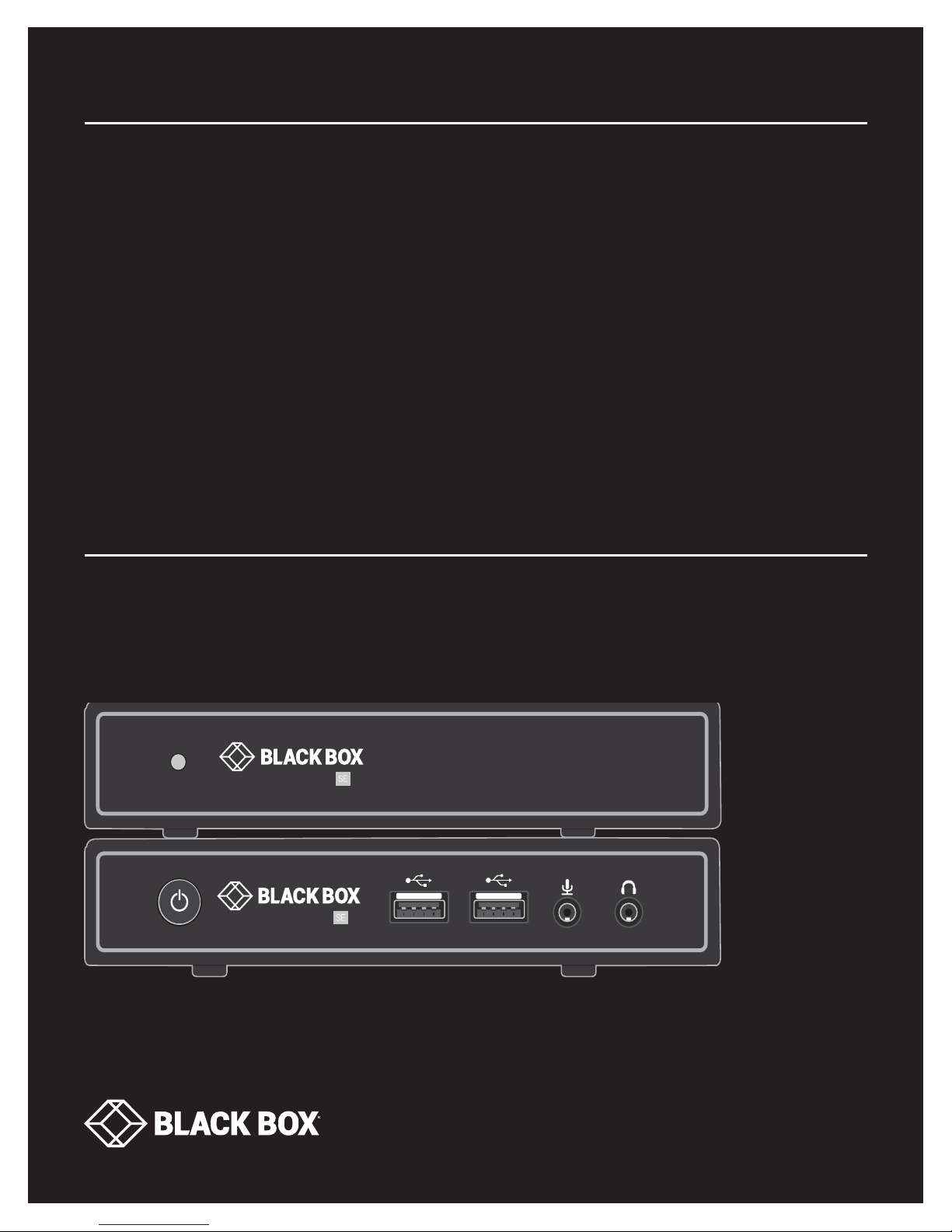
FIGURE 5-1. FRONT VIEW OF EMERALD SE RECEIVER, SINGLE-HE AD (EMD2000SE-R)
5 6 7 8 9 10 11
FIGURE 5-2. REAR VIEW OF EMERALD SE RECEIVER, SINGLE-HEAD (EMD2000SE-R)
FIGURE 5-3. FRONT VIEW OF EMERALD SE RECEIVER, DUAL-HEAD (EMD2002SE-R)
5 6 7 8 9 10 10
FIGURE 5-4. REAR VIEW OF EMERALD SE RECEIVER, DUAL-HEAD (EMD2002SE-R)
18
1
1. 8 7 7. 8 7 7. 2 2 6 9 BLACKBOX.COM
2 3 4
Page 19

CH APT E R 5: INSTALL ATION
TABLE 5-1. EMERALD SE RECEIVER COMPONENTS
NEED HELP?
LEAV E TH E TEC H TO US
LIVE 24/7
TECHNICAL
SUPPORT
1. 8 7 7. 8 7 7. 2 2 69
NUMBER IN FIGURES 5-1
THROUGH 5-4
1 Power button
2, 6 (4) USB Type A connectors Link to USB devices
3 (1) 3.5-mm connector Connects to microphone
4 (1) 3.5-mm connector Connects to speakers
5
7 (1) Link/Activity LED Lights green when there is activity on the link
8 (1) RJ-45 connector Links to 10 -/100-/100 0 -Mbps network
9 (1) Link Speed LED
10 (1) or (2) DVI output connectors Links to DVI output(s)
11 (1) DB9 connector* Links to RS-232 serial interface
COMPONENT DESCRIPTION
Disabled;
NOTE: The unit automatically powers on; it must be turned off at the power source.
(1) 2.5-mm barrel connector
for power
Links to 5-VDC external in-line power supply
LED blinks green 1= 10 Mbps, 2 = 100 Mbps and 3= 1 Gbps in a 1.5 second interval.
No blinking means no valid link
*Single-head model only
1. 8 7 7. 8 7 7. 2 2 6 9 BLACKBOX.COM
19
Page 20

NEED HELP?
LEAV E TH E TEC H TO US
LIVE 24/7
CH APT E R 5: INSTALL ATION
5.6 CONNECT THE EMERALD SE TRANSMITTER
Before connecting the Emerald SE Transmitter to the remote workstation, ensure that the resolution and the refresh rate of the
remote workstation are supported by the Emerald SE system. Set the screen resolution and refresh rate of the remote workstation.
Unsupported settings will cause blank or distorted video at the Receiver.
The recommended sequence to connect the Transmitter is:
1. Turn off the remote workstation.
2. The Emerald SE Transmitter has one USB connector. Connect it to a corresponding USB port on the remote workstation.
3. Connect the video connector(s) on the Emerald SE Transmitter to the appropriately labeled port on the workstation(s) using the
DVI cable(s).
4. Connect one end of the UTP cable to the Emerald SE Transmitter’s RJ-45 connector and turn on the workstation.
5. Route the other end of the UTP cable to the location you have chosen for the Emerald SE Receiver. If necessary, you can extend
the UTP cable via an Ethernet switch (subject to normal Ethernet cabling practices).
6. Plug the external power supply’s 2.5-mm connector into the DC power jack on the rear of the Emerald SE Transmitter.
7. Connect the detachable power cord to the power supply.
8. Plug the power cord into an appropriate wall outlet. The transmitter powers on automatically.
9. Turn on power for the remote workstation.
NOTE: Use only the power supply provided by Black Box.
TECHNICAL
SUPPORT
1. 8 7 7. 8 7 7. 2 2 69
1
FIGURE 5-5. FRONT VIEW OF THE EMERALD SE TRANSMITTER, SINGLE-HEAD (EMD2000SE-T)
2 3 4 5 6 7 8 9 10
FIGURE 5-6. REAR VIEW OF THE EMERALD SE TRANSMITTER, SINGLE-HEAD (EMD2000SE-T)
20
1. 8 7 7. 8 7 7. 2 2 6 9 BLACKBOX.COM
Page 21

CH APT E R 5: INSTALL ATION
1
FIGURE 5-7. FRONT VIEW OF THE EMERALD SE TRANSMITTER, DUAL-HEAD (EMD2002SE-T)
9 10
NEED HELP?
LEAV E TH E TEC H TO US
LIVE 24/7
TECHNICAL
SUPPORT
1. 8 7 7. 8 7 7. 2 2 69
2 3 4 5 6 7 7
FIGURE 5-8. REAR VIEW OF THE EMERALD SE TRANSMITTER, DUAL-HEAD (EMD2002SE-T)
TABLE 5-2. EMERALD SE TRANSMITTER COMPONENTS
NUMBER IN FIGURES 5-4
THROUGH 5-8
1 Power LED
2
3 (1) USB Type B connector Links to USB input source
4 (1) Link/Activity LED Lights green when there is activity on the link
5 (1) RJ-45 connector Links to 10 -/100-/100 0 -Mbps network
6 (1) 10/100/10 00-Mbps L ED Lights green when data is being transmtted at 1000 Mbps
7 (1) or (2) DVI input connectors Links to DVI input sources
8 (1) RJ-45 connector* Links to RS-232 serial interface
9 (1) 3.5-mm connector Links to audio
10 (1) 3.5-mm connector Links to audio
*Single-head model only
COMPONENT DESCRIPTION
Disabled;
NOTE: The unit automatically powers on; it must be turned off at the power source.
(1) 2.5-mm barrel connector
for power
Links to 5-VDC external in-line power supply
1. 8 7 7. 8 7 7. 2 2 6 9 BLACKBOX.COM
21
Page 22

NEED HELP?
LEAV E TH E TEC H TO US
LIVE 24/7
CH APT E R 6: N E T WO RKED INS TA LLATION
6.1 POINT-TO-POINT INSTALLATION
In a point-to-point configuration, no administrator setup of the Emerald SE Transmitter or the Emerald SE Receiver is required.
This enables you to install the system quickly, directly out-of-the-box. However, in the point-to-point configuration, you can install
only one Emerald SE Transmitter and Emerald SE Receiver pair on a subnet, and both must be on the same subnet unless a router
is present in the network to span subnets.
Also if there are other devices with 192.168.1.21 (default Receiver IP address) or 192.168.1.22 (default Transmitter IP address) on
the network, then the IP addresses for Receiver and/or Transmitter should be changed to unused IP addresses.
6.2 UNMANAGED OR MANAGED MATRIX INSTALLATION
The following instructions will enable you to install your Emerald SE Receiver and Emerald SE Transmitter in a networked
configuration. In this installation, multiple Emerald SE Transmitters and Emerald SE Receivers are attached via the same Ethernet
network. In this case, it is important for each unit to be configured with a unique IP address.
The Emerald SE Receiver has been preconfigured with factory-default network settings. If you install multiple units on the same
network, you will need to assign a unique IP address to each unit or configure the Receiver for DHCP. This can be done via the
On-Screen Display (OSD) on the Emerald SE Receiver and must be carried out before adding multiple devices on the same network.
TECHNICAL
SUPPORT
1. 8 7 7. 8 7 7. 2 2 69
TABLE 6-1. EMERALD SE SYSTEM DEFAULT NETWORK SETTINGS
COMPONENT IP ADDRESS TYPE DEFAULT GATEWAY SUBNET MASK
Emerald SE Receiver (EMD2000SE-R, EMD2002SE-R) 192.168.1. 21 Static 192 .16 8 .1.1 255.255.255.0
Emerald SE Transmitter (EMD2000SE-T, EMD2002SE-T) 192.168.1. 22 Static 192 .16 8 .1.1 255.255.255.0
Boxilla Manager (BXAMGR) 192.168.1. 24 Static 192 .16 8 .1.1 255.255.255.0
22
1. 8 7 7. 8 7 7. 2 2 6 9 BLACKBOX.COM
Page 23

NEED HELP?
LEAV E TH E TEC H TO US
LIVE 24/7
CHAPTER 7: OPERATION OF EMERALD SE SYSTEM
Operating a workstation through the Emerald SE system is no different than working directly connected to a PC desktop.
All peripherals operate as if directly connected, even though the workstation is located at a distance.
7.1 LED IDENTIFICATION
Front panel
There is one button on the front panel of an Emerald SE unit. This button is disabled.
NOTE: The unit powers on automatically when plugged in and must be turned off at the power source.
Rear panel
Two LEDs are built into the RJ-45 connectors on the Emerald SE Receiver, Manager and Transmitter. The definition of the operation
of these LEDs is shown in Table 7-1.
TABLE 7-1. RJ-45 CONNECTOR LEDS ON THE REAR PANEL
OF THE EMERALD SE RECEIVER, MANAGER AND TRANSMITTER
TECHNICAL
SUPPORT
1. 8 7 7. 8 7 7. 2 2 69
LED S TATUS DESCRIPTION
Green ON Linked OK
Activity
Link Speed
7.2 ACCESSING THE SYSTEM
Green Flashing Transmit/Receive activity
Green OFF No Link
Blinks green one time 10 Mbps
Blinks green two times 100 Mbps
Blinks green three times 1000 Mbps
No blinking No valid link
A connection is established using the OSD on an Emerald SE Receiver or Boxilla Manager. Once you are connected, a series
of messages will be displayed on the screen to inform you of the progress of the connection. You will be able to interact with the
remote workstation as if it were located at your desk.
NOTE: If the remote workstation is powered off, the Emerald SE system will display a “black” screen for video when a connection
is made.
1. 8 7 7. 8 7 7. 2 2 6 9 BLACKBOX.COM
23
Page 24

NEED HELP?
LEAV E TH E TEC H TO US
LIVE 24/7
CHAPTER 8: OSD FUNCTIONS
The Emerald SE Receiver and Boxilla Manager incorporate an On-Screen Display (OSD) that allows you to view information about
the configuration of your system and potentially also allows for setting connections and configuration parameters such as the IP
address, depending on the type of user. The following sections describe the operation common on a Receiver.
8.1 USER TYPES
The Emerald SE system supports three classes of users for Matrix products:
1. Administrator – users of this class have full rights to configure the system. They can create/modify/delete new users and
connections, change network settings, etc.
2. Power User – users of this class can modify resolution for connections to virtual desktops and change his/her local password.
3. Standard User – users of this class can only select from a list of pre-defined connections to access and view system
information. They cannot change any configuration settings.
8.2 LOG ON
A user must log-on to the Emerald SE Receiver or Boxilla Manager to configure and manage the Emerald SE system. The log-on
screen is shown in Figure 8-1. The username defines the access rights and configuration available to the user.
TECHNICAL
SUPPORT
1. 8 7 7. 8 7 7. 2 2 69
The fields on this screen are:
Username: the username to log-on as defined by the Administrator. Username is case-sensitive.
Password: password for the user. Password is case-sensitive.
Remember Me: When this box is checked, the unit keeps the username between log-ons and power-cycles. When this box is not
checked, the username field is always presented as blank when powered-up and after a log-out. This tick-box only affects the
username – the password is never preserved.
Power Button: This button allows the user to reboot the client.
24
FIGURE 8-1. OSD LOG-ON SCREEN
1. 8 7 7. 8 7 7. 2 2 6 9 BLACKBOX.COM
Page 25

NEED HELP?
LEAV E TH E TEC H TO US
LIVE 24/7
CHAPTER 8: OSD FUNCTIONS
TECHNICAL
SUPPORT
1. 8 7 7. 8 7 7. 2 2 69
FIGURE 8-2. LOG-ON SCREEN - REBOOT BUTTON
System Preferences: This button has a drop down menu that allows the user to define system preferences for the Emerald SE
Receiver. Figure 8-3 shows how the keyboard type can be selected.
Help: This button opens a pop-up window with help on that screen.
8.3 DEFAULT USERNAME AND PASSWORD
The Emerald SE Receiver ships with a default username of admin with a blank password (i.e. no password). This user cannot be
deleted, but the password can be changed.
NOTE: If you create a password for the default Admin account and forget it, there is no way to reset / retrieve it unless using a
Boxilla manager. We recommend that the administrator creates a second Admin account for critical systems in case the main
Admin account is locked out.
FIGURE 8-3. SETTING SYSTEMS KE YBOARD TYPE
1. 8 7 7. 8 7 7. 2 2 6 9 BLACKBOX.COM
25
Page 26

NEED HELP?
LEAV E TH E TEC H TO US
LIVE 24/7
CHAPTER 8: OSD FUNCTIONS
8.4 USER VIEWS AND CAPABILITIES
There are three different types of users in the Emerald SE System. Your user type will determine what exactly you will see on your
OSD. For the purpose of this Manual, we show the screen of an Administrator. This means that some buttons shown here may not
be available to other users.
The Emerald SE comes as an unmanaged system and as a managed system. There are some differences in the OSD for these
systems which you may see here..
8.5 CONNECTIONS SCREEN
When a user successfully logs on to the Emerald SE Receiver or Manager, the Connection screen is displayed. This is shown in
Figure 8-4. The connections that a user can make are listed in the connection window. The user logged on is shown
in the top right corner of the OSD.
TECHNICAL
SUPPORT
1. 8 7 7. 8 7 7. 2 2 69
Def ault _TX _192 .16 8 .1. 2 2
NOTE: Default_TX
is 192 .168.1.22
FIGURE 8-4. CONNECTION SCREEN
If the user is an Administrator type, the three buttons on the left (New, Edit, and Remove) will be displayed. These allow the user
to create, edit, or remove connections. For Standard User types, no connections can be created, edited, or removed, so these
buttons are not displayed or are greyed out.
By default, there is one connection called “Default Tx - 192.168.1.22” that defines a connection to an Emerald SE Transmitter
with its factory defaults. A maximum of 32 connections can be defined for an Emerald SE Receiver by default, and these
connections can be shared by users as defined by an administrator (different users can have the same connection). The number of
connections can be increased to unlimited in a managed domain via Boxilla upgrade licenses.
26
1. 8 7 7. 8 7 7. 2 2 6 9 BLACKBOX.COM
Page 27

NEED HELP?
LEAV E TH E TEC H TO US
LIVE 24/7
CHAPTER 8: OSD FUNCTIONS
8.5.1 CREATING A NEW CONNECTION
To allow an Emerald SE Receiver or Manager to connect to a target Emerald SE Transmitter, an administrator must create a
connection. The administrator clicks on the New button on the Connections screen. This causes the New Connections pop-up
window to appear as shown in Figure 8-5.
TECHNICAL
SUPPORT
1. 8 7 7. 8 7 7. 2 2 69
FIGURE 8-5. NEW CONNECTION WINDOW
The fields on this screen are:
Name: this is a unique name for the new connection. The name can be between 1 and 32 characters. The name can be
composed of any Alphanumeric characters and special characters except for “ ”/ \ [ ] : ; | = , + * ? < > `’.
IP Address/Host Name: IP Address of Emerald SE Transmiter (if Connection Via set to Transmitter) or VM in IP v4 format.
Alternatively it can be the Host Name if this can be resolved in the local DNS server. Note: Using Host Name will increase the
switching time by the time needed to resolve the Host Name to an IP address;
Port: defines the port to be used for the RDP connection for connections via VM Direct or Broker. Uses 3389 by default;
Username: defines username to be used on a VM connection. Only used for connections via VM Direct or Broker. If left “blank” on
VM Direct – user will be presented with Windows Login screen on VM;
Password: defines username to be used on a VM connection. Only used for connections via VM Direct or Broker;
Domain: defines domain that a Virtual Machine is part of (if part of a windows domain). Not used for connections to Transmitters.
Load Balance Info: defines resource on the broker (VM pool) that the Receiver will attempt to connect to after user credentials have
been validated. Only used on connections via Broker;
Connection Type: used to define whether a connection is Private or Shared (i.e. others connections of type Shared can join in
session and share Keyboard, Video and Mouse). Only available if Connection Via is set to Transmitter;
1. 8 7 7. 8 7 7. 2 2 6 9 BLACKBOX.COM
27
Page 28
NEED HELP?
LEAV E TH E TEC H TO US
LIVE 24/7
CHAPTER 8: OSD FUNCTIONS
Enable Extended Desktop: Remote connections can be extended for dual-head Emerald units by enabling the option Extended
Desktop. Enable Extended Desktop setting enables the second video head of a dual head Transmitter. Make sure both the video
heads on the Transmitter are connected to the source. Video heads on the receiver are connected to respective monitors.
Enable View Only mode: View only setting for a connection allows user to monitor what is been transmitted from a source without
being able to interact with the source. This feature allows a user or administrator to monitor the actions on the network without
accidentally interacting with other users. View only connection is available in both private and shared mode connections with or
without analog audio.
Enable USB Redirection: when set, this enables non-keyboard and non-mice devices (such as tablets and USB headsets)
to be redirected for this connection.
Enable Audio: when set, this enables audio to be supplied to the remote audio connectors.
Enable NLA: when set, this enables Network Level Authentication requiring that the user be authenticated to the RD Session Host
server before the session is created. This is not used for when Connection Via is set to Transmitter.
Persistent Connection: When turned on, Persistent Connection will constantly try to connect the Receiver with the Transmitters until
successful. This is useful when using Emerald SE for digital signage or an application that does not need a keyboard/mouse to stay
connected to a defined source.
TECHNICAL
SUPPORT
1. 8 7 7. 8 7 7. 2 2 69
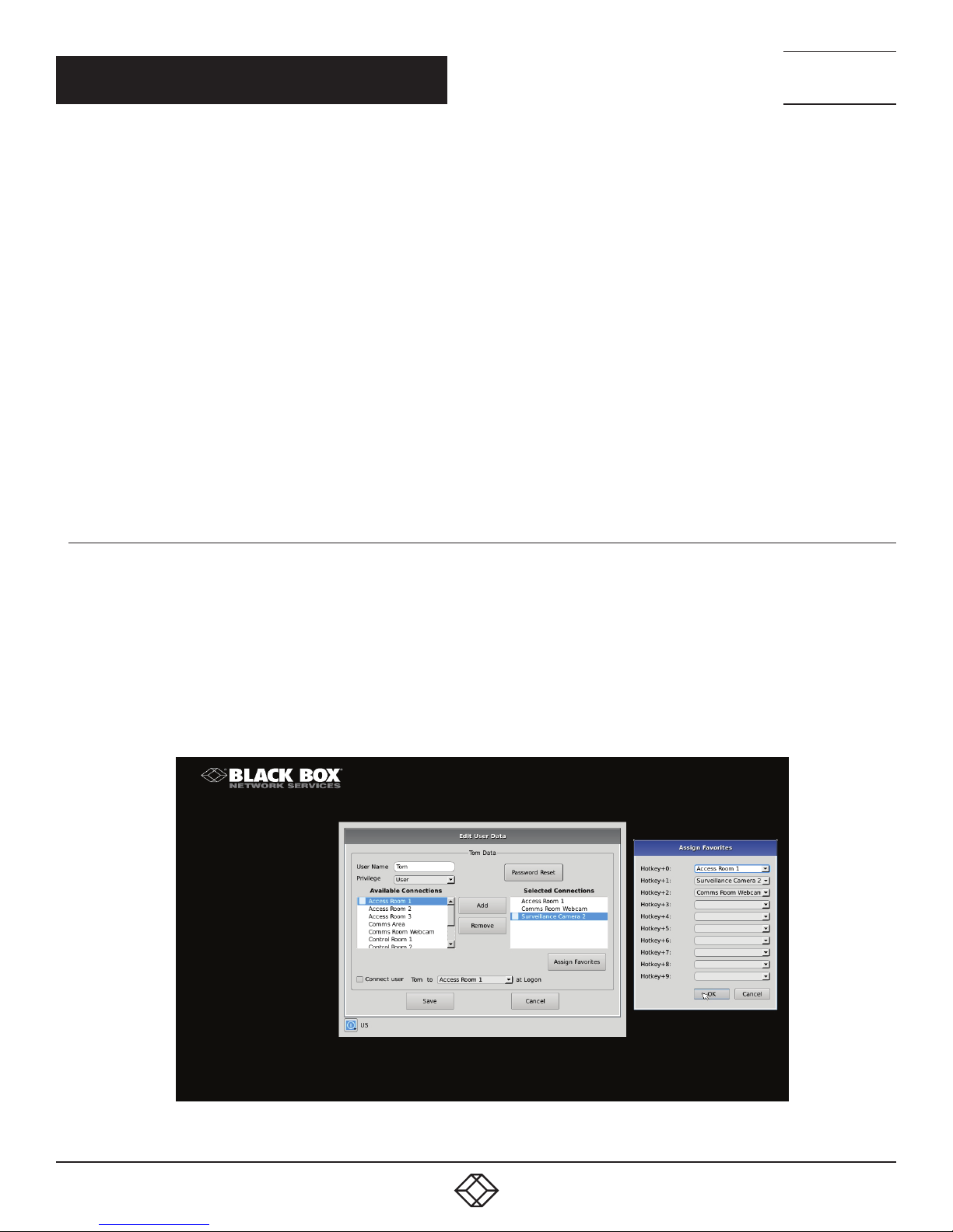
8.5.2 CONNECTION FAVORITES
Connection favorites provide a quick convenient mechanism for users to switch between their pre-defined connections. Favorites
are configured by the administrator where a maximum of 10 favorites can be assigned to users using a combination of hotkey and
[0-9].
Assigning Connection Favorites
A pre-requiste is that the user exists and has connects assigned.
The following screenshot demonstrates the administrator assigning connections for the user to the available hotkeys. Favorites do
not need to be allocated sequentially and hotkeys can be skipped.
28
FIGURE 8-6. ASSIGNING CONNECTION FAVORITES
1. 8 7 7. 8 7 7. 2 2 6 9 BLACKBOX.COM
Page 29

CHAPTER 8: OSD FUNCTIONS
Listing Connection Favorites:
When a user log in they can view their assigned favorites.
NEED HELP?
LEAV E TH E TEC H TO US
LIVE 24/7
TECHNICAL
SUPPORT
1. 8 7 7. 8 7 7. 2 2 69
FIGURE 8-7. LISTING CONNECTION FAVORITES
8.5.3 CONNECTING
To make a connection, the user highlights the required “connection” in the window and then clicks on the “ Connect” button.
Alternatively, a user can double-click on the connection. This action causes the Emerald SE Receiver to attempt to connect
to the target remote workstation or virtual machine. If the target is available, the connection will be made.
If another user is already connected to the target defined in the connection, the user will receive a pop-up window indicating
the target device is already allocated.
8.5.4 EDIT CONNECTION
To edit a connection and change its parameters, an administrator clicks on the Edit button on the Connections screen. The Edit
Connections pop-up window appears.
The administrator changes required fields and clicks Save to confirm or Cancel to discard any changes.
8.5.5 REMOVE CONNECTION
To remove or delete a connection, an administrator highlights a connection in the list and then clicks on the Remove button
on the Connections screen (shown in Figure 8-8). This causes the Remove Connection pop-up window to appear where a user
confirms the removal or cancels the attempt.
1. 8 7 7. 8 7 7. 2 2 6 9 BLACKBOX.COM
29
Page 30

NEED HELP?
LEAV E TH E TEC H TO US
LIVE 24/7
CHAPTER 8: OSD FUNCTIONS
8.6 CONTROL TAB
The Control Tab on the OSD enables an administrator to change the configuration of the Emerald SE system. The Control Tab is
shown in Figure 8-8.
TECHNICAL
SUPPORT
1. 8 7 7. 8 7 7. 2 2 69
FIGURE 8-8. CONTROL TAB
FIGURE 8-9. GENERAL SETTINGS
30
1. 8 7 7. 8 7 7. 2 2 6 9 BLACKBOX.COM
Page 31
NEED HELP?
LEAV E TH E TEC H TO US
LIVE 24/7
CHAPTER 8: OSD FUNCTIONS
There are five functions that can be accessed on this tab:
1. Preferences – allows users to change preference settings for:
i. Power-Mode Settings – allows changing of the power mode configuration.
ii. Resolution Settings – allows change of preferred resolution for OSD screens and Virtual connections.
iii. Hot-Key Settings – allows changing of the active hot-key for keyboard short-cuts.
iv. Timer Settings – allows setting of pre-emption timer and various inactivity timers
v. General Settings - used to redirect touch screens
2. Network – allows administrator to change network parameters for the Emerald SE Receiver or Manager.
3. System – allows upgrading of unit firmware, reset unit to factory defaults, and to save/restore unit configuration to a USB drive.
4. Password – change the administrator or user password.
5. Transmitter – allows changing of Transmitter parameters.
8.6.1 PREFERENCES
TECHNICAL
SUPPORT
1. 8 7 7. 8 7 7. 2 2 69
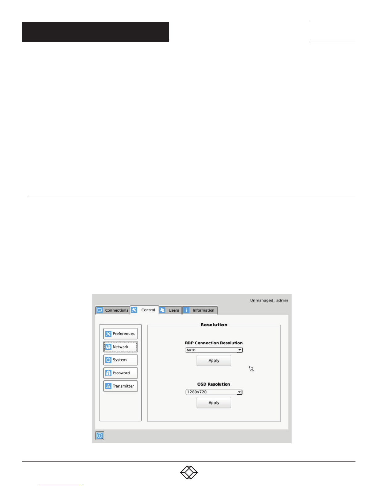
Resolution
The Resolution button allows an administrator or power user to set the preferred resolution for the RDP Connection and for the
OSD. By default, both the RDP Resolution and the OSD Resolution are set to Auto.
The RDP Connection Resolution allows the resolution to be changed for an RDP connection, (i.e. defines the resolution that the
virtual desktop will be accessed with). If the preferred resolution is not supported, the Receiver will use the next highest resolution
supported by both monitor and Receiver.
The OSD Resolution is set to Auto by default, but can be changed to the available OSD resolutions if the user wants to set
a specific resolution. This setting has no effect when connecting to an Emerald SE Transmitter.
Click Apply button to save the change.
FIGURE 8-10. RESOLUTION SCREEN
1. 8 7 7. 8 7 7. 2 2 6 9 BLACKBOX.COM
31
Page 32

NEED HELP?
LEAV E TH E TEC H TO US
LIVE 24/7
CHAPTER 8: OSD FUNCTIONS
Hot-Key
The Hot-Key button allows the administrator to change the hot-key configuration. The hot-key is used with the “o” key to terminate
the current connection and bring up the OSD. The hot-key with “p” key is used to switch to the previous connection without loading
the OSD. Example: PrtScrn, O (default).
TECHNICAL
SUPPORT
1. 8 7 7. 8 7 7. 2 2 69
FIGURE 8-11. HOT KEY DEFINITION
The default hot-key is Print-Screen (PrntScrn). The alternatives are shown in the table. Click the Apply button to confirm a hot-key
change.
TABLE 8-1. HOTKEY SEQUENCES
SEQUENCE ACTION
Print Screen (Default) -press Prnt Scrn key
Ctrl + Ctrl -press Ctrl key twice within 1 second
Alt + Alt -press Alt key twice within 1 second
Shift + Shift -press Shift key twice within 1 second
Open OSD: Hotkey O Switch to previous target: Hotkey P
Mouse-Left + Right -press mouse left and right buttons at the same time for 2 seconds
The “Enable Functional Key” tick-box is used to disable the use of the function keys after the hot-key. So only the Hot-Key is required
to bring up the OSD. The Enable functional Key is set by default.
32
1. 8 7 7. 8 7 7. 2 2 6 9 BLACKBOX.COM
Page 33

NEED HELP?
LEAV E TH E TEC H TO US
LIVE 24/7
CHAPTER 8: OSD FUNCTIONS
TECHNICAL
SUPPORT
1. 8 7 7. 8 7 7. 2 2 69
Timer Settings
There are 2 timer settings available to users as shown in Figure 8-12. By default, they are turned off. If you wish to turn them on,
you have to select the desired timer, set the time you wish, and click apply. The three timer settings are:
1. OSD Inactivity Timer – This sets a limit on how long a user can be logged on to the OSD without any keyboard or mouse
activity. Once the user reaches the inactivity timer, he/she will be logged out of the OSD. The timer value can be set to a number
from 2 to 60 minutes.
2. Connection Inactivity Timer – This sets a limit on how long a user can be connected to a source (virtual machine, Transmitter etc.)
without any keyboard or mouse activity. Once the session reaches the inactivity timer, he/she will be logged out of their connection
and return to the OSD. The timer value can be set to a number from 2 to 60 minutes.
NOTE: Inactivity occurs when the mouse or keyboard is not pressed or moved for a set period of time.
FIGURE 8-12. TIMER SETTINGS
1. 8 7 7. 8 7 7. 2 2 6 9 BLACKBOX.COM
33
Page 34

NEED HELP?
LEAV E TH E TEC H TO US
LIVE 24/7
CHAPTER 8: OSD FUNCTIONS
8.6.2 NETWORK
The network screen shown in Figure 8-13 allows an administrator to change the settings for the Emerald SE Receiver or Manager.
The default network setting for the Receiver is a static IP address of 192.168.1.21. It has a Network Mask of 255.255.255.0 and a
Gateway 192.168.1.1. If DHCP is selected, the Receiver gets its IP address from the DHCP server. Click the Apply button to confirm
any changes to network settings.
NOTE: Only IPv4 addressing supported in current firmware version.
TECHNICAL
SUPPORT
1. 8 7 7. 8 7 7. 2 2 69
FIGURE 8-13. NETWORK SETTINGS
34
1. 8 7 7. 8 7 7. 2 2 6 9 BLACKBOX.COM
Page 35

NEED HELP?
LEAV E TH E TEC H TO US
LIVE 24/7
CHAPTER 8: OSD FUNCTIONS
TECHNICAL
SUPPORT
1. 8 7 7. 8 7 7. 2 2 69
8.6.3 S Y S T EM
The System screen shown in Figure 8-14 allows an administrator to upgrade the firmware in the Emerald SE Receiver, reset it to
factory defaults, import/export the configuration to an external USB drive, and perform a system diagnostic.
FIGURE 8-14. SYSTEM SCREEN
System Upgrade
The Emerald SE Receiver can be upgraded from a USB Flash drive. Simply take the “firmware.clu” file and place it in the root
directory of the flash drive. When you click the Upgrade button, the “valid” upgrade files on the USB drive are displayed. A valid file
has the extension .clu – an example is shown in Figure 8-15. If the flash drive isn’t recognized, format the drive using Fat32 file system.
FIGURE 8-15. UPGRADE FILES
1. 8 7 7. 8 7 7. 2 2 6 9 BLACKBOX.COM
35
Page 36

NEED HELP?
LEAV E TH E TEC H TO US
LIVE 24/7
CHAPTER 8: OSD FUNCTIONS
Once the administrator has selected the file and clicked Ok, the system checks that the selected file has no errors before
upgrading the Emerald SE Receiver. The configuration of the unit is preserved through the upgrade.
Restore Factory Defaults
The administrator can click the Restore button to reset the Receiver back to factory defaults.
Connection Broker Settings
TECHNICAL
SUPPORT
1. 8 7 7. 8 7 7. 2 2 69
FIGURE 8-16. CONNECTION BROKER SETTING SCREEN
The Web Access Server setting is used to allow access to a local copy of Active Directory. If this setting is configured
correctly, then if a user who is not configured in the local database attempts to login, the device will redirect the username and
password to the local active directory installation and validate the user credentials.
If the user is validated, the Active Directory Server will return a valid VM pool-name to the device. The device sends this pool-name
information to the Connection Broker which then allocates a Virtual Machine to the User, provided a VM is available.
On the Receiver when the user attempts to login, the login will now take the following steps in this order:
1. The login credentials are checked to see if the user is configured locally on the Receiver. Should the user exist, they will be logged
in as normal. If not, then step two will occur. If neither “Connect via Web Access Server” nor “Connect via Connection Broker
Server” is ticked, the Receiver at login will only attempt to authenticate the user locally. This is the default setting.
2. If the Web Access Settings are configured, the Receiver will attempt to launch a connection to an RD Web Access server. This will
allow the user to be Authenticated against the Domain Controller (Active Directory) allowing the user to access Virtual Desktop
Pools and Personal Virtual desktops.
To enable the receiver to access an RDWeb server at login, apply the following settings.
1. The Web Access Address should be the login page of the local RD Web Access Server using its IP address, e.g.
https://192.168.10.7/RDWeb/Pages/en-US/login.aspx.
36
1. 8 7 7. 8 7 7. 2 2 6 9 BLACKBOX.COM
Page 37

CHAPTER 8: OSD FUNCTIONS
NOTE: We currently do not support hostnames in the web address so please use the IP of the Web Access server.
You must place the full address to the login page of the RD Web Access server (https://*************.apsx).
NEED HELP?
LEAV E TH E TEC H TO US
LIVE 24/7
TECHNICAL
SUPPORT
1. 8 7 7. 8 7 7. 2 2 69
FIGURE 8-17. CONNECTION BROKER SETTINGS FOR WEB ACCESS SERVER
2. Enter the local Connection Broker IP address.
3. Enter in the local domain name.
Alternatively, the user credentials can be validated by using the local Connection Broker. In this case, the User Credentials are sent to
the Connection Broker. If accepted, then the broker will return the IP address of a local VM from the pool and a connection is made.
NOTE: We currently do not support hostnames, so use the IP of the connection broker server.
FIGURE 8-18. CONNECTION BROKER SETTINGS FOR CB SERVER
1. 8 7 7. 8 7 7. 2 2 6 9 BLACKBOX.COM
37
Page 38

NEED HELP?
LEAV E TH E TEC H TO US
LIVE 24/7
CHAPTER 8: OSD FUNCTIONS
Tick the box “Connect Via Connection Broker Server” to enable connection using local Connection Broker Server. Then enter the
following settings:
1. Enter in the domain name as defined on the local network.
2. Enter in your load balance address as defined in the local server configured, e.g. tsv://VMResource.1.Win7Pool.
Export Settings
The Export option exports an encrypted version of the Receiver configuration to an attached memory stick. This can be used as a
backup mechanism for an individual receiver or manager or it can be used to port configurations from one Receiver to another.
The data in the export file consists of User, Connection and device information from the exporting device.
Import Settings
The Import option imports an encrypted version of a Receiver configuration from an attached memory stick. This can be used to
recover an old backup from the same Receiver or it can be used to port configurations from another Receiver.
The data in the file consists of User, Connection and some device information from the exporting device.
The following settings are not imported.
1. OSD Preferred Resolution
2. Static IP address. In this case, if the importing device is set to static but the import file has a DHCP configuration, then the device
configuration is changed to DHCP. Likewise, if the local device was DHCP and the import file was Static, the device
configuration is change to Static but with its last configured Static IP address, not that of the imported file. If both local device and
import file have a Static IP address configured, there is no change to the device configuration, i.e. the IP address is not changed.
TECHNICAL
SUPPORT
1. 8 7 7. 8 7 7. 2 2 69
NOTE: If the Import function is on the Manager, then the file must come from another Manager with the same Licensed Capabilities
or the import will not proceed.
System Diagnostics
The diagnostics provides information for Black Box to debug customer encountered issues. When this button is clicked the user is
asked to save the diagnostics onto a memory stick in the Receiver unit. This file should be sent back to Black Box for analysis. There
is a similar diagnostic that can be run on a transmitter.
Password
The Password button when clicked allows the current user’s password to be changed. This button is only visible to Administrators.
38
FIGURE 8-19. PASSWORD CHANGE
1. 8 7 7. 8 7 7. 2 2 6 9 BLACKBOX.COM
Page 39

NEED HELP?
LEAV E TH E TEC H TO US
LIVE 24/7
CHAPTER 8: OSD FUNCTIONS
TECHNICAL
SUPPORT
1. 8 7 7. 8 7 7. 2 2 69
Transmitter Button
The Transmitter button on the Control Tab allows administrators to change the configuration of an Emerald SE Transmitter (this
button is only visible to administrators). The following options are available when the Transmitter button has been activated:
1. Transmitter Information
2. Transmitter Firmware Upgrade
3. Transmitter restore factory defaults
4. Transmitter reboot
5. Transmitter Preferences
6. Network Settings
7. Discover Transmitter IP address
Configuring a Transmitter
To configure a Transmitter, the IP address must be defined for the target Transmitter. When there is no active IP address defined, the
TX Setting window has all the buttons grayed out except for the Apply and Discover buttons.
The IP address for the transmitter can be entered into the field at the top of window and click Apply button to activate. If a valid IP
address is entered, the Transmitter settings window makes all the options available for the administrator shown in Figure 8-20.
Alternatively the Discover button can be used to find the IP address of a transmitter. First click the Discover button and follow the
instructions. Basically once in discovery mode, the Receiver (or Boxilla Manager) can capture the IP address from a Transmitter once
it has been power-cycled.
NOTE: The default network setting for the Transmitter is a static IP address of 192.168.1.22. It has a Network Mask
of 255.255.255.0 and a Gateway 192.168.1.1.
FIGURE 8-20. TRANSMITTER SETTINGS CONFIGURATION WINDOW - ACTIVE IP ADDRESS
1. 8 7 7. 8 7 7. 2 2 6 9 BLACKBOX.COM
39
Page 40

NEED HELP?
LEAV E TH E TEC H TO US
LIVE 24/7
CHAPTER 8: OSD FUNCTIONS
If the IP address of the Receiver and Transmitter are not on the same subnet, a router is required to allow them to communicate. This
is true even when the Receiver “discovers” the Transmitter’s IP address. One way to avoid this is to change the Receiver address to
be on the same subnet as the Transmitter, make the required configuration changes to the Transmitter, and then change the Receiver
back to its required IP address.
Transmitter Information
The Information button provides Transmitter related information such as Device Model, Serial Number, MAC address, and current
Firmware Version to the administrator.
If the active IP address is not the address of a valid Emerald SE Transmitter or this address is unreachable, an error message is
returned.
Transmitter Upgrade
The administrator can click the Upgrade button to change the firmware on a Transmitter. The upgrade file is selected from the set of
files on an attached USB drive. These files will have the extension .clu . The selected file is checked to be a valid Transmitter upgrade
file before starting the upgrade. The OSD provides a series of screens to walk the user through the process.
The upgrade can take a few minutes to complete and the power to the Transmitter and the Receiver must not be disconnected during
the upgrade. During the upgrade process, the Transmitter may reboot.
If the active IP address is not the address of a valid Emerald SE Transmitter or this address is unreachable, an error message is
returned.
TECHNICAL
SUPPORT
1. 8 7 7. 8 7 7. 2 2 69
Transmitter Restore Factory Defaults
The administrator can click the Restore button to reset the Transmitter back to factory defaults. If the active IP address is not the
address of a valid Emerald SE Transmitter or this address is unreachable, an error message is returned.
Transmitter Reboot
The administrator can click the Reboot button to power-cycle the Transmitter. If the active IP address is not the address of a valid
Emerald SE Transmitter or this address is unreachable, an error message is returned.
Transmitter Preferences
The administrator can click the Transmitter Preferences to change Video Quality Setting or HID Configuration. When the Transmitter
Preferences button is clicked the window shown in Figure 8-21 pops up.
40
1. 8 7 7. 8 7 7. 2 2 6 9 BLACKBOX.COM
Page 41

CHAPTER 8: OSD FUNCTIONS
NEED HELP?
LEAV E TH E TEC H TO US
LIVE 24/7
TECHNICAL
SUPPORT
1. 8 7 7. 8 7 7. 2 2 69
FIGURE 8-21.
Transmitter Video Quality Settings
1. Best Quality – lossless compression, pixel-perfect mode of operation. Generally needs dedicated network to ensure no frame
loss.
2. Visually Lossless Compression – high quality visual image. Some compression on stream to reduce bandwidth to allow
operation on standard corporate networks. Compression does not vary based on available network bandwidth, so may lead
to some dropped frames during network congestion periods.
3. Optimized Quality (default) – system tuned to maintain visually lossless compression while increasing compression level during
periods of network congestion to reduce frame loss. Balances visual quality with frame loss in periods of congestion (i.e.
attempts to reduce/eliminate frame loss).
4. Optimized Bandwidth – system tuned to maintain visually lossless compression but increased levels of compression level during
periods of network congestion to reduce frame loss. Optimized towards lower bandwidth during congestion periods compared
to level 3.
5. Lowest Bandwidth – high level of compression to minimize average network bandwidth. No dynamic change to compression
levels – always seeking to reduce bandwidth.
If the active IP address is not the address of a valid Emerald SE Transmitter or this address is unreachable, an error message is
returned.
HID Configurations
The HID configuration can be set to be default which allows Audio over USB as well as keyboard and mouse connections or Basic
HID which provide compatibility with DKM, DCX and older servers that require a keyboard and mouse HID only.
Basic HID is also required to access any computer’s BIOS menus.
1. 8 7 7. 8 7 7. 2 2 6 9 BLACKBOX.COM
41
Page 42

NEED HELP?
LEAV E TH E TEC H TO US
LIVE 24/7
CHAPTER 8: OSD FUNCTIONS
Absolute mouse:
This feature can be used to enable interoperability with KM switches with built-in “Glide & Switch” capability such as ServSwitchTC
and Freedom. For normal usage, where mouse is directly connected to Receiver, then the Default or Basic options should be used.
OSD option:
TECHNICAL
SUPPORT
1. 8 7 7. 8 7 7. 2 2 69
FIGURE 8-22. ABSOLUTE MOUSE OSD OPTION
Video Source Optimization
The transmitter can be configured to handle different applications by changing the way it handles the video signal if it natively
has embedded noise (i.e. from a VGA to DVI converter). You can choose to use “DVI optimized”, “VGA high performance”, “VGA
optimized”, or “VGA low bandwidth” settings. You may change these options to get the best performance out of the transmitter.
EDID Settings
The transmitter can support native EDID options such as “1920x1080”, “1920x1200”, “1680x1050”, “1280x1024”, “1024x768”, or
you can choose to use the remote monitor EDID by clicking on the Generate Clone button which will copy the remote EDID to the
transmitter. The computer may need to be restarted in order for the settings to work. If you find that changing the EDID settings
makes the remote monitor blank out, you may need to select a different option to make it work.
Transmitter Network Settings
The administrator can click the Network Settings button to edit the Transmitter Network Settings.
To change the IP address settings for a Transmitter, the administrator can enter the new IP address, subnet mask, and gateway, and
then click on the Apply button.
42
1. 8 7 7. 8 7 7. 2 2 6 9 BLACKBOX.COM
Page 43

CHAPTER 8: OSD FUNCTIONS
NEED HELP?
LEAV E TH E TEC H TO US
LIVE 24/7
TECHNICAL
SUPPORT
1. 8 7 7. 8 7 7. 2 2 69
FIGURE 8-23. TRANSMITTER NETWORK SETTINGS WINDOW
If the new IP address for the Emerald SE Transmitter is on a different subnet than the Receiver, the Receiver or Manager will not be
able to communicate with it without going through a router. This is the case even on a point-to-point link between devices.
If the entered IP address is not the address of a valid Emerald SE Transmitter or this address is unreachable, an error message is
returned.
Discover Transmitter IP Address
This requires the Transmitter to be connected to the Receiver on a point-to-point link or be the only Transmitter on the attached
network. in this case, the administrator can click on the Discover button and follow the wizard to discover the IP address of the
attached Transmitter. This is required in the case when an administrator does not know the IP address of the Transmitter.
Transmitter Diagnostics
The Transmitter provides diagnostics information for Black Box to debug customer encountered issues. When this button is
clicked the user is asked to save the diagnostics onto a memory stick in the Receiver unit. Send this file back to Black Box for
analysis.
8.7 MANAGING USERS
Users are defined in the Emerald SE system to provide rights to manage the system, rights to connect to different target devices
and set parameters for connections. There are three types of users that can be created in an Emerald SE system.
1. Administrator – users of the class have full rights to configure the system. They can create/modify/delete new users and
connections, change network settings, etc.
2. Power User – users of this class can modify resolutions for connections to virtual desktops and change his/her local password.
3. Standard Users – users of this class can only select from a list of pre-defined connections to access and view system
information. They cannot change any configuration settings.
1. 8 7 7. 8 7 7. 2 2 6 9 BLACKBOX.COM
43
Page 44

NEED HELP?
LEAV E TH E TEC H TO US
LIVE 24/7
CHAPTER 8: OSD FUNCTIONS
The Emerald SE Receiver and Boxilla have one default user – admin, which is a member of the administrator group. This user is
defined by default and cannot be deleted. An Emerald SE Receiver or Manager can have a maximum of 32 users defined, unless in a
manager domain with an “upgrade” license installed. With the upgrade license installed, unlimited users can be defined.
To manage users, an administrator selects the Users tab (this Tab is only visible to Administrator class users).
admin
TECHNICAL
SUPPORT
1. 8 7 7. 8 7 7. 2 2 69
FIGURE 8-24. USER SCREENS
8.7.1 ADD A USER
To add a user, click the add button. This causes the New-User window to be displayed.
8.7.2 AUTO LOG ON
When the Log-on button is selected and a user is chosen, this user will be automatically logged on after power is applied to unit or
after a reboot.
44
1. 8 7 7. 8 7 7. 2 2 6 9 BLACKBOX.COM
Page 45

CHAPTER 8: OSD FUNCTIONS
Def ault _TX _192 .16 8 .1. 2 2
NOTE: Default_TX
is 19 2.168.1.22
NEED HELP?
LEAV E TH E TEC H TO US
LIVE 24/7
TECHNICAL
SUPPORT
1. 8 7 7. 8 7 7. 2 2 69
FIGURE 8-25. NEW USER WINDOW
When adding a new user, the following fields are used to define the user:
User Name: This is a unique name that uses 1–32 characters. The username can be any valid username for a Microsoft O/S.
This means the username cannot contain “ ”/ \ [ ] : ; | = , + * ? < > `’.
Password: This field can be a minimum of 0 characters (i.e. blank) and a maximum of 32 characters. The password can be any valid
password for a Microsoft O/S. This means the password cannot contain “ ”/ \ [ ] : ; | = , + * ? < > `’
Confirm Password: This field must match the Password field. If there is a mismatch, a message is presented to the user in a
pop-up screen.
Privilege: This field, which is a drop-down list, defines the type of user the new user will be—Administrator or User.
Selected Connections: The new user must be allocated Connections that he/she can access. These are selected from the Available
Connections window by the user selecting a set of connections (click on the connection in the Available Connection window and
then click the “Add” button). This causes the selected connections to be “added” to a user’s selected connection window.
Connect to at login: This tick box defines whether the Emerald SE Receiver or Manager attempts to connect immediately to the
selected connection after a logon by the user. This automatic connection only occurs after a logon. If a user exits the connection,
the connection tab is displayed to the user for selection of a connection. This Connect to at Login is only saved when the Save
button is clicked. If not clicked and another tab is selected, the changes are ignored. If not ticked, no automatic connection is made
on log-in.
Once the new user fields have been filled out, the Save button must be clicked to create the new user. Clicking the Save button
causes the validation of the new username checking that it is unique and that the two password entries match. If this validation
fails, a pop-up window displays the reason for the failure – and the new user is not created. After dismissing the pop-up window,
the user can fix the error and click Save again.
The Cancel button should be clicked if the new user is not to be created.
1. 8 7 7. 8 7 7. 2 2 6 9 BLACKBOX.COM
45
Page 46

CHAPTER 8: OSD FUNCTIONS
8.7.3 EDIT A USER
To edit a user, click on the Edit button. This causes the Edit-User window (shown in Figure 8-26) to be displayed.
NEED HELP?
LEAV E TH E TEC H TO US
LIVE 24/7
TECHNICAL
SUPPORT
1. 8 7 7. 8 7 7. 2 2 69
FIGURE 8-26. EDIT USER WINDOW
This window allows the user privilege type, the permitted connections available, the password, and the auto-connect option
to be changed.
The default “admin” account gets access to all connections; this list cannot be modified. Other administrator-type users can have
their connection list modified.
Once the changes have been made for a user, they only become active once the Save button has been clicked. The changes can be
abandoned by clicking the Cancel button.
46
1. 8 7 7. 8 7 7. 2 2 6 9 BLACKBOX.COM
Page 47

CHAPTER 8: OSD FUNCTIONS
8.7.4 REMOVE A USER
To remove a user, highlight the user’s name and press “Remove.”
admin
NEED HELP?
LEAV E TH E TEC H TO US
LIVE 24/7
TECHNICAL
SUPPORT
1. 8 7 7. 8 7 7. 2 2 69
FIGURE 8-27. REMOVE USER
When the Remove button is clicked, a pop-up window is displayed to prompt confirmation that this user is to be deleted. Click the Yes
button to remove the user. Clicking the No button causes this action to be aborted and the user is not removed.
NOTE: There must always be a user of the name admin in the Emerald SE system so the system can always be administrated. When
attempting to remove the user, the system checks if the username is admin before it will allow the user to be removed.
1. 8 7 7. 8 7 7. 2 2 6 9 BLACKBOX.COM
47
Page 48

NEED HELP?
LEAV E TH E TEC H TO US
LIVE 24/7
APPENDIX A: EMERALD SE VIDEO RESOLUTIONS SUPPORTED
The Emerald SE supports the resolutions listed below:
640 x 480 @ 60 Hz
640 x 480 @ 75 Hz
800 x 600 @ 60 Hz
800 x 600 @ 70 Hz
800 x 600 @ 72 Hz
800 x 600 @ 75 Hz
800 x 600 @ 85 Hz
1024 x 768 @ 60 Hz
1024 x 768 @ 75 Hz
1024 x 768 @ 85 Hz
1280 x 800 @ 60 Hz
1280 x 960 @ 60 Hz
1280 x 960 @ 85 Hz
1280 x 1024 @ 60 Hz
1280 x 1024 @ 75 Hz
1280 x 1024 @ 85 Hz
1366 x 768 @ 60 Hz
1400 x 1050 @ 60 Hz
1440 x 900 @ 60 Hz
1600 x 900 @ 60 Hz
1680 x 1050 @ 60 Hz
1600 x 1200 @ 60 Hz
1680 x 1050 @ 60 Hz
1280 x 720 @ 60 Hz
1920 x 1080 @ 60Hz
1920 x 1200 @ 60 Hz
Emerald SE also will pass all the above resolutions at refresh frequencies from 15 Hz to 60 Hz. Those with non-defined VESA
resolutions will be displayed at 60 Hz even if the incoming resolution is not 60 Hz.
TECHNICAL
SUPPORT
1. 8 7 7. 8 7 7. 2 2 69
48
1. 8 7 7. 8 7 7. 2 2 6 9 BLACKBOX.COM
Page 49

NEED HELP?
LEAV E TH E TEC H TO US
LIVE 24/7
APPENDIX B. CONFIGURING WINDOWS 7 VIRTUAL MACHINES
TECHNICAL
SUPPORT
1. 8 7 7. 8 7 7. 2 2 69
A few properties must be configured on a target Windows Virtual Machine for Emerald SE to connect with it.
On the Windows Virtual Machine click on the Start button and launch a command window. Then launch group policy editor –
gpedit.msc.
Start >> Run >> “cmd” >> “gpedit.msc”
Once the Local group Policy editor is open follow this path:
Computer Configuration >> Administrative Templates >> Windows Components >> Remote Desktop Services >> Remote Desktop
Session Host >> Remote Session Environment
Ensure the following three policies are set as follows:
1. Optimize visual experience when using RemoteFX.
For this policy set both the “Screen Capture Rate” and “Screen Image Quality” to Highest.
2. Configure RemoteFX.
Set this policy to enabled
3. Limit maximum color depth.
Set this policy to “Client Compatible.”
Once the above policies have been applied, reboot the Virtual Machine. It is now enabled for Emerald SE connections.
There are different settings to optimize the performance of Emerald SE with different Windows operating systems. These are
defined in the application note – Emerald SE Group Policies for Optimal Performance for Windows Targets.
It is not possible to connect to a transmitter from a computer/laptop running RDP. A receiver is always required.
1. 8 7 7. 8 7 7. 2 2 6 9 BLACKBOX.COM
49
Page 50

NEED HELP?
LEAV E TH E TEC H TO US
LIVE 24/7
APPENDIX C. EMERALD SE NETWORK PROTOCOLS OVERVIEW
Emerald SE uses standard IP protocols for communication between Receivers and Transmitters. Port 3389 is used for unicast
communications.
For management purposes some other ports are used. The Black Box Discovery protocol used UDP Multicast Group 224.0.1.249
(port 39150). This is sent by the Manager to discover Emerald SE devices in the network. The router must allow UDP Multicast
forwarding to allow devices on subnet different to where Manager is located to be discovered.
Emerald SE devices respond to the discovery multicast by sending a UDP unicast back to Manager IP address on the same port
(Por t 3915 0).
Once an Emerald SE device is part of the managed domain, the Manager periodically “audits” the device to determine information
such as if the device on-line, who is logged into devices, device statistics, etc. These audit requests and responses are unicast
UDP to specific IP addresses (responses are sent back to Manager’s IP address) on port 39150.
On power-up, a Transmitter sends out a “here I am” multicast message on multicast group 225.0.0.37 on port 12345.
As part of management configuration, the Manager may communicate to a specific device on port 22 (TCP unicast
communications).
Emerald SE can operate across multiple VLANs or subnets. Basic IP networking rules need to be followed; there should be a router
in the network to enable the various devices on different subnets to communicate with each other.
To allow Black Box’s Emerald SE discovery protocol to operate, Multicast routing should be enabled. Black Box’s Emerald SE
“discovery” protocol is not required for Emerald SE systems to operate but it is recommended to enable an Emerald SE Manager to
search
for devices across the network. If the Emerald SE discovery protocol is not enabled, i.e. router does not have multicast routing
enabled, the administrator will have to manually add in all devices not on its subnet, i.e. add in each device individually
by its IP address.
TECHNICAL
SUPPORT
1. 8 7 7. 8 7 7. 2 2 69
50
1. 8 7 7. 8 7 7. 2 2 6 9 BLACKBOX.COM
Page 51

NEED HELP?
LEAV E TH E TEC H TO US
LIVE 24/7
APPENDIX D. TROUBLESHOOTING
This page covers some basic notes & troubleshooting when using the Emerald SE.
Operating Modes: Connecting to an Emerald SE transmitter from an RDP client that is from a laptop / computer is not possible; you
must use an Emerald SE receiver for this. An Emerald SE receiver can connect to an Emerald SE transmitter and RDP server.
TABLE D-1. OPERATING MODES CONFIGURATIONS
USER SIDE COMPUTER SIDE OPERATION
Laptop/Computer w/RDP Client Emerald SE Transmitter This is not supported and will not work
Emerald SE Receiver Emerald SE Transmitter Fully supported
Emerald SE Receiver RDP Server on VM or OS Fully supported
Sluggish Mouse: When using the Emerald SE, you may find that the mouse is not being very responsive, or has a noticeable delay.
This can typically occur if the video card is using Dithering technology. You can contact Black Box to get a small utility to disable
video card dithering on AMD graphics cards.
Error Codes: The following error codes expanded.
1 GENERAL_ERROR Connection protocol failure. Are units at the correct and compatible software version?
2 INIT_FAIL Can’t start protocol. Is the receiver at the correct software version?
3 GET_SOCKET Protocol Start Failure Are units at the correct and compatible software version?
4 CREATE_SESSION_FAIL Can’t create session. Is transmitter connected and powered on?
5 CONNECT_FAIL Can’t create session. “Is transmitter connected and powered on? Is port 22 open between units.”
6 TX_CHECK_FAIL Target device is not a transmitter. Is transmitter IP address correct?
7 VER_CHECK_FAIL Can’t read device Version. Is transmitter connected and powered on?
8 LED_FLASH_FAIL Start LED Flash command failed on remote device Is transmitter connected and powered on?
9 FILE_SEND_FAIL Can’t send upgrade file to transmitter. Is transmitter connected and powered on?
10 PERMISSION_CHANGE_FAIL Update to change settings on Transmitter Is transmitter connected and powered on?
11 EXTRACT_UPGRADE_FAIL Failed to extract upgrade file. Is upgrade file correct or damaged?
12 RUN_UPGRADE_FAIL Upgrade failed Is upgrade file correct or damaged?
13 REBOOT_FAIL Failed to reboot remote device unit. Is remote device connected and powered on?
14 FILE_SEARCH_FAIL Upgrade file format failed Is upgrade file correct or damaged?
15 LISTEN_ERROR Connection protocol failure. “Are units at the correct and compatible software version? Is transmitter
connected and powered on?”
16 SOCKET_OPTION_ERROR Connection protocol failure. “Are units at the correct and compatible software version?
Is transmitter connected and powered on?”
17 SOCKET_BIND_ERROR Connection protocol failure. “Are units at the correct and compatible software version?
Is transmitter connected and powered on?”
18 RECVFROM_ERROR Connection protocol failure. “Are units at the correct and compatible software version?
Is transmitter connected and powered on?”
19 GET_INFO_FAIL Failed to retrieve Info tab from remote device “Are units at the correct and compatible software version?
Is transmitter connected and powered on?”
20 COMPATIBILITY_FAIL Upgrade file is incompatible with version on unit Please check release notes for correct version and
compatibility information.
TECHNICAL
SUPPORT
1. 8 7 7. 8 7 7. 2 2 69
1. 8 7 7. 8 7 7. 2 2 6 9 BLACKBOX.COM
51
Page 52

NEED HELP?
LEAV E TH E TEC H TO US
LIVE 24/7
APPENDIX D. TROUBLESHOOTING
21 BRAND_CHECK_FAIL This is not a correct upgrade file for Emerald SE Please check release notes for correct version and
compatibility information.
22 CLASS_CHECK_FAIL Can’t upgrade Transmitter with Receiver file or visa versa. Please check release notes for correct
version and compatibility information.
23 PACKAGE_CHECK_FAIL Incorrect upgrade file for this model Please check release notes for correct version and
compatibility information.
24 NO_UPGRADE_REQUIRED No upgrade required. This version of code is already on thedevice. No upgrade required.
TECHNICAL
SUPPORT
1. 8 7 7. 8 7 7. 2 2 69
52
1. 8 7 7. 8 7 7. 2 2 6 9 BLACKBOX.COM
Page 53

NEED HELP?
LEAV E TH E TEC H TO US
LIVE 24/7
APPENDIX E. REGULATORY INFORMATION
E.1 FCC STATEMENT
This equipment has been found to comply with the limits for a Class A digital device, pursuant to Part 15 of the FCC Rules. These
limits are designed to provide reasonable protection against harmful interference when the equipment is operated in a commercial
environment. This equipment generates, uses, and can radiate radio frequency energy and, if not installed and used in accordance
with the instruction manual, may cause harmful interference to radio communications. Operation of this equipment in a residential
area is likely to cause harmful interference in which case the user will be required to correct the interference at his own expense.
Changes or modifications not expressly approved by the party responsible for compliance could void the user’s authority to
operate the equipment.
Shielded cables must be used with this equipment to maintain compliance with radio frequency energy emission regulations and
ensure a suitably high level of immunity to electromagnetic disturbances.
All power supplies are certified to the relevant major international safety standards.
TECHNICAL
SUPPORT
1. 8 7 7. 8 7 7. 2 2 69
1. 8 7 7. 8 7 7. 2 2 6 9 BLACKBOX.COM
53
Page 54

NEED HELP?
LEAV E TH E TEC H TO US
LIVE 24/7
APPENDIX E. REGULATORY INFORMATION
E.2 NOM STATEMENT
1. Todas las instrucciones de seguridad y operación deberán ser leídas antes de que el aparato eléctrico sea operado.
2. Las instrucciones de seguridad y operación deberán ser guardadas para referencia futura.
3. Todas las advertencias en el aparato eléctrico y en sus instrucciones de operación deben ser respetadas.
4. Todas las instrucciones de operación y uso deben ser seguidas.
5. El aparato eléctrico no deberá ser usado cerca del agua—por ejemplo, cerca de la tina de baño, lavabo, sótano mojado o cerca de
una alberca, etc.
6. El aparato eléctrico debe ser usado únicamente con carritos o pedestales que sean recomendados por el fabricante.
7. El aparato eléctrico debe ser montado a la pared o al techo sólo como sea recomendado por el fabricante.
8. Servicio—El usuario no debe intentar dar servicio al equipo eléctrico más allá a lo descrito en las instrucciones de operación.
Todo otro servicio deberá ser referido a personal de servicio calificado.
9. El aparato eléctrico debe ser situado de tal manera que su posición no interfiera su uso. La colocación del aparato eléctrico
sobre una cama, sofá, alfombra o superficie similar puede bloquea la ventilación, no se debe colocar en libreros o gabinetes que
impidan el flujo de aire por los orificios de ventilación.
10. El equipo eléctrico deber ser situado fuera del alcance de fuentes de calor como radiadores, registros de calor, estufas u otros
aparatos (incluyendo amplificadores) que producen calor.
11. El aparato eléctrico deberá ser connectado a una fuente de poder sólo del tipo descrito en el instructivo de operación, o como
se indique en el aparato.
12. Precaución debe ser tomada de tal manera que la tierra fisica y la polarización del equipo no sea eliminada.
13. Los cables de la fuente de poder deben ser guiados de tal manera que no sean pisados ni pellizcados por objetos colocados
sobre o contra ellos, poniendo particular atención a los contactos y receptáculos donde salen del aparato.
14. El equipo eléctrico debe ser limpiado únicamente de acuerdo a las recomendaciones del fabricante.
15. En caso de existir, una antena externa deberá ser localizada lejos de las lineas de energia.
16. El cable de corriente deberá ser desconectado del cuando el equipo no sea usado por un largo periodo de tiempo.
17. Cuidado debe ser tomado de tal manera que objectos liquidos no sean derramados sobre la cubierta u orificios de ventilación.
18. Servicio por personal calificado deberá ser provisto cuando:
A: El cable de poder o el contacto ha sido dañado; u
B: Objectos han caído o líquido ha sido derramado dentro del aparato;o
C: El aparato ha sido expuesto a la lluvia; o
D: El aparato parece no operar normalmente o muestra un cambio en su desempeño; o
E: El aparato ha sido tirado o su cubierta ha sido dañada.
TECHNICAL
SUPPORT
1. 8 7 7. 8 7 7. 2 2 69
54
1. 8 7 7. 8 7 7. 2 2 6 9 BLACKBOX.COM
Page 55

NEED HELP?
LEAV E TH E TEC H TO US
LIVE 24/7
APPENDIX F. DISCLAIMER/TRADEMARKS
TECHNICAL
SUPPORT
1. 8 7 7. 8 7 7. 2 2 69
F.1 DISCLAIMER
Black Box Network Services shall not be liable for damages of any kind, including, but not limited to, punitive, consequential or cost of
cover damages, resulting from any errors in the product information or specifications set forth in this document and Black Box
Network Services may revise this document at any time without notice.
F.2 TRADEMARKS USED IN THIS MANUAL
Black Box and the Double Diamond logo are registered trademarks of BB Technologies, Inc.
Any other trademarks mentioned in this manual are acknowledged to be the property of the trademark owners.
1. 8 7 7. 8 7 7. 2 2 6 9 BLACKBOX.COM
55
Page 56

NEED HELP?
LEAVE THE TECH TO US
LIVE 24/7
TECHNICAL
SUPPORT
1.87 7. 8 77. 2 2 6 9
© COPYRIGHT 2019. BLACK BOX CORPORATION. ALL RIGHTS RESERVED.
EMD2000SE_ USER_RE V2-FOR-5.1.PDF
 Loading...