

Page 1

GPS Network Time Server
GPS Network Time Sever:
LEU9070
GPS Antenna 25dB:
LEU9071
Antenna Cable (25 metres):
EHNU9070
Configuration Cable:
EHNU9071
TECHNICAL:
SALES:
FAX:
ADDRESS:
WEB:
(0118) 965 6000
(0118) 965 5100
(0118) 965 5001
464 Basingstoke Road, Reading, Berkshire RG2 0QN
www.blackbox.co.uk
Page 2

2
GPS Network Time Server
SALES: 0118 965 5100
How To Contact your Local Black Box
Italy: Australia:
Black Box Italia S.P.A Black Box Catalog Australia PTY LTD
Tel: 02.27.400.280 Tel: 039879 7100
Fax: 02.27.400.219 Fax: 039870 2955
Web Site: www.blackbox.it
Deutschland: Brazil:
Black Box Deutschland Black Box Do Brasil.
Tel: 0811/5541-0 Tel: (011) 5515-4000
Fax: 0811/5541-499 Fax: (011) 5515-4002
Web Site: www.blackbox-deutschland.com Web Site: www.blackbox.com.br
Switzerland: Canada:
Datacom Black Box Services AG Black Box Canada Corp.
Tel: 055 451 70 70 Tel: 0416-736-8000
Fax: 055 451 70 75 Fax: 0416-736-7348
Web Site: www.black-box.ch Web Site: www.blackbox.com
Netherlands: Mexico:
Black Box Datacom BV Black Box De Mexico S.A. de C.V
Tel: 030-2417700 Tel: (5)-420-0100
Fax: 030-2417777 Fax: (5)-420-0123
Web Site: www.blackbox.nl/ Web Site: www.blackbox.com.mx
Belgium: Japan:
Black Box Black Box Catalog
Tel: 02/725.85.50 Tel: (03) 3820-5011
Fax: 02/725.92.12 Fax: (03) 3820-5010
Web Site: www.blackbox.be Web Site: www.blackbox.co.jp/
Page 3

3
GPS Network Time Server
TECHNICAL: 0118 965 6000
France: U.S.A
Black Box Catalogue Black Box Corporation
Tel: 01.45.60.67.00 Tel: 724-746-5500
Fax: 01.45.60.67.47 Fax: 724-746-0746
Web Site: www.blackbox.fr Web Site: www.blackbox.com
Spain: Chile
Black Box Comunicaciones S.A. Black Box Chile
Tel: 091 663 0200 Tel: 6680 141
Fax: 091 661 84 35 Fax: 6680 140
Web Site: www.blackbox.es Web Site: www.Blackbox.cl
Page 4

4
GPS Network Time Server
SALES: 0118 965 5100
Contents
Introduction..............................................................................................................................................6
Product Description..................................................................................................................................7
General.......................................................................................................................................7
Standard functions......................................................................................................................8
Dimensions and weight............................................................................................................... 8
Front and rear panel drawings....................................................................................................8
Quick Start Guide...................................................................................................................................10
Step One – connecting the server to a configuration terminal...................................................10
Profile name.................................................................................................................11
Port…….......................................................................................................................11
Log File ………………………………………………………………………………………..11
Clock Name.................................................................................................................11
Target….......................................................................................................................11
Step 2 – Connection to the Network.........................................................................................11
Step 3 – Connecting the antenna..............................................................................................11
Step 4 – Positioning the antenna..............................................................................................11
Step 5 – Using the software...................................................................................................... 11
Step 6 – Enabling servers to use the GPS Network Time server over your network.................12
Start-Up..................................................................................................................................................13
Preliminary connections............................................................................................................13
Connection quality.................................................................................................................... 14
Starting the clock...................................................................................................................... 14
Operating faults.........................................................................................................................16
Setting out of service................................................................................................................16
Operation...............................................................................................................................................17
Adjusting to UTC time...............................................................................................................17
Time keeping............................................................................................................................ 17
NTP server operation................................................................................................................18
Maintenance..........................................................................................................................................19
Performance Characteristics..................................................................................................................20
Environment..............................................................................................................................20
Internal time generation............................................................................................................20
Frequency outputs.............................................................................................................. ......20
NTP reference accuracy...........................................................................................................20
Page 5

5
GPS Network Time Server
TECHNICAL: 0118 965 6000
Input/Output Characteristics...................................................................................................................22
Power supplies..........................................................................................................................22
"Antenna" input.........................................................................................................................22
"RS 232" output (J4).................................................................................................................23
"1-pps" output (J5)....................................................................................................................23
"FREQ." Outputs (J6, J7, J8, J9)..............................................................................................24
"IRIG" output.............................................................................................................................25
"AUI" output..............................................................................................................................25
"10BaseT" output......................................................................................................................25
"ALARM" output (J1).................................................................................................................26
"TOD" output (J3)......................................................................................................................26
Terminology...........................................................................................................................................28
Glossary.................................................................................................................................................29
Page 6

6
GPS Network Time Server
SALES: 0118 965 5100
Introduction
This manual is the installation and operating manual for the GPS Network Time Server and
accessories.
• GPS input antenna,
• Mains power input (90 to 265V / 48 to 63 Hz),
• DC power supply input (18 to 32 VDC),
• Four 10 MHz outputs (>10 dBm / 50),
• 1-pps output (TTL / 50),
• Time stamp output (RS232C),
• Alarm output (relay contact),
• Remote control interface (RS232C),
• Ethernet output, 10 MHz, AUI or 10BaseT,
• IRIG output, NFS 87-500 standard compliant.
The manual describes the device components, on-site installation, commissioning, operation
in regular service, troubleshooting information and user-accessible maintenance.
A summary of performance and a description of the clock inputs/outputs are also given for
information.
The product-specific terminology is explained in on page 24. The main abbreviations used in
the document are detailed in the glossary.
Page 7

7
GPS Network Time Server
TECHNICAL: 0118 965 6000
Product Description
General
The GPS Network Time Server meets the precise synchronization and syntonization
requirements of local and remote users.
The GPS Network Time Server offers highly accurate and stable frequency sources
synchronized and slaved on the reception of signals transmitted by the GPS satellite
constellation.
The clock operates on a stand-alone basis, in a predefined setting. This configuration can be
modified by the user, via the remote control interface.
The clock integrates a GPS receiver used to deliver, at user level, the time/frequency
reference broadcast by the GPS system. It autonomously uses the integrity aspects of this
system (TRAIM); i. e. it automatically rejects the signals transmitted by satellites considered
as faulty, which might impair the clock’s performance.
The time reference thus obtained is processed by high performance algorithms, which control
the internal frequency pilot of the unit. The system is used to distribute frequency and time
signals (1-pps second signal) locally, and time stamp and synchronization messages remotely,
via Ethernet network under IP or by IRIG signal over amplitude coded on s ymmetrical pair.
Distribution under IP is performed using the NTP protocol for which the GPS Network Time
Server is a primary timeserver.
In case of GPS reception loss, the clock maintains the time and frequency distribution from
its internal pilot. Also, learning of the frequency pilot behaviour (effects resulting from
ageing and temperature variations, in the presence of the GPS reference), it is used to
improve the time and frequency distribution performance when the GPS is lost.
Most functions of the GPS Network Time Server are software controlled. At start-up, the unit
runs self-tests of its hardware resources, it checks that its internal pilot is stabilized and
makes a first coarse adjustment of the distributed frequency. After half an hour of operation,
the frequency accuracy is of 1.10-9 and the time accuracy is less than 1 s relative to
UTC(GPS) time.
As a timeserver on IP protocol, the GPS Network Time Server includes a DHCP and a
BOOTP client. Those clients automatically set to the configuration of the GPS Network Time
Server as it is connected to server configured IP network. Through the remote control link,
the GPSNTSTP external software enables the configuration of an address mask for
broadcasting to specified subnets.
Page 8

8
GPS Network Time Server
SALES: 0118 965 5100
Standard functions
The GPS Network Time Server is designed to generate, maintain and deliver:
• A time reference synchronized with the UTC (GPS) time. The unit delivers a 1PPS
signal and a time stamp message for this signal;
• A frequency reference (four 10 MHz outputs);
• A time stamp signal with one second repetition (TOD output);
• A frequency and time reference via a 1KHz carrier modulated by the time and date
(IRIG output);
• A time service on an Ethernet network, under IP and NTP protocols.
The clock is supplied with an AC or DC voltage. These two voltage sources are both
connected to provide full redundancy.
The user can access the clock status data via the remote control interface. Sets of commands
are also available to the user to initialise or set up the clock.
The synthetic status of the system operation is reported locally on the three front panel
indicator lights.
In the event of a hardware failure, a relay contact output closes.
The GPS Network Time Server is fully automatically operated. The IP address and the subnet
masks can be modified through the remote contr ol access. The GPS Network Time Server
requires no maintenance operation over a 10-year period.
Dimensions and weight
The GPS Network Time Server can be mounted in a standard 19-inch rack.
Height:1 U (44 mm)
Width: 19'' (483 mm)
Depth: 13.5 “ (340 mm)
Weight: < 5 Kg
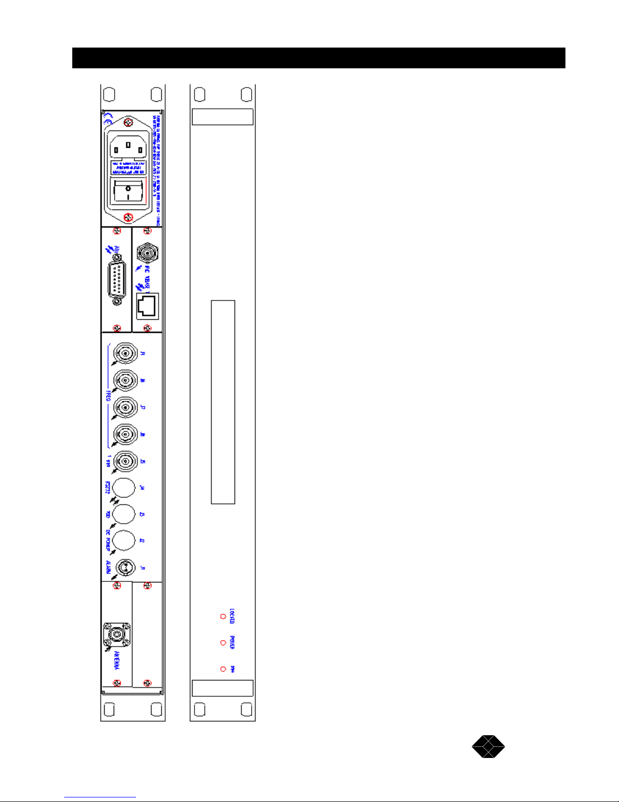
Front and rear panel drawings
(See overleaf)
Page 9
9
GPS Network Time Server
TECHNICAL: 0118 965 6000
Page 10

10
GPS Network Time Server
SALES: 0118 965 5100
Quick Start Guide
This section breaks down the installation of the GPS Network Time Server, into an easy to
follow step-by-step guide.
Step One – connecting the server to a configuration terminal
After unpacking your GPS Network Time Server, connect it to a PC for configuration. Take
the configuration cable, (EHNU9071) and plug the 8-pin DIN connector into the port labelled
“RS232” on the back of the server. Connect the 9-pin D type connector into a free comm
port on your PC.
Now take the CD supplied with the GPS Network Time Server and insert it in to your CD
drive. Your PC will now automatically load the software and take you through to the
welcome screen. From here to create a new session you must select MANAGE and then
NEW.
You are now presented with a screen that looks as follows:
Page 11

11
GPS Network Time Server
TECHNICAL: 0118 965 6000
Profile name
The name entered in this box will be the name of the file that contains the profile parameters.
Port
This box allows you select a serial port through which you can configure the GPS Time
Server.
Log File
Enter here the name of the file where you would like alarm logs to be recorded.
Clock Name
This label will be used in the log file.
Target
“NTP” must be selected in this box. This is relevant if flash upgrades are performed.
Step 2 – Connection to the Network
Attach the GPS Network Time Server to your network hub or switch using a straight
Category 5 patch lead.
After connecting to the network, use the configuration software and serial configuration cable
to set the IP address and subnet mask. Please see your network manager for a spare IP
address. Alternatively, select the DHCP setting for the time server to obtain a dynamically
assigned IP address at startup. Networking par ameters are set via the Setup and then the
N
etwork menu.
After configuring the IP parameters, reboot the server from the C
lock toolbar.
Step 3 – Connecting the antenna
Unpack the antenna, (LEU9071) and the antenna cable (EHNU9070) now connect the
antenna to the cable, and the cable to the antenna port on the back of the server.
Step 4 – Positioning the antenna
The antenna should be mounted horizontally outside with a clear 360-degree view of the sky.
Step 5 – Using the software
The software is used to monitor and control the GPS Time Server. It is used to set-up the
slaving of the GPS Time Server to the GPS source.
Explanations of each of the software menus can be found in the help menu.
Page 12

12
GPS Network Time Server
SALES: 0118 965 5100
After following the steps 1-4 the equipment has to lock on to the GPS sources and
synchronise, this can take up to 30-minutes. When synchronisation is complete, the "locked"
LED on the front panel, will turn green.
A "power" LED also goes green when the temperature of th e powe r supply and internal clock
source have stabilised. This also takes around 30 minutes.
Enabling the GPS status menu from the Display toolbar of the software allows you to watch
the clock lock onto the different satellites. It requires three satellites to get valid time, and
four to determine correct altitude. The clock can then work with any number of satellites
between one and eight.
As soon as all the "status" fields turn green the GPS Time Server will be fully synchronised
and ready to provide a GPS time source to your network.
Step 6 – Enabling servers to use to GPS Network Time server over your network
To enable servers on your network to use the GPS Network Time Server, they will need to be
loaded with a piece of Daemon software.
This Daemon software can be found on many web sites, here are two possible sites:
http://www.accessone.com/~thinkman/dimension4/
www.infres.enst.fr/~dax/services/rfc
Appearances vary, but you will need to enter the IP address and name of the server, and select NTP,
or SNTP protocols for the Daemon software to communicate with the server.
Page 13

13
GPS Network Time Server
TECHNICAL: 0118 965 6000
Start-Up
Preliminary connections
Before starting up the GPS Network Time Server, the following operations should be
performed:
• Place the system so that the lower and upper cooling air inlets are not obstructed.
• Place the GPS antenna outdoor in a position such that it views the sky directly over
360 degrees (e. g. at the top of an antenna mast).
CAUTION
The GPS Network Time Server is designed to operate exclusively with the
recommended GPS antenna. Connecting another antenna can turn the system
inefficient, or even damage it irreversibly.
• Connect the antenna to the Antenna connector. For the GPS signals to be received
correctly, the antenna-cable-lightening arrester assembly should have a gain in the
range from 3 to 33 dB.
Typical antenna mounting:
G1 + G2 + G3 = 40 dB - 15 dB - 1 dB = 24 dB
We actually have: 3 dB < G1 + G2 + G3 = 24 dB < 33 dB
Page 14

14
GPS Network Time Server
SALES: 0118 965 5100
• Connect the power supply circuit to the mains socket, or connect a DC power supply
(24V for Series 2S or 48V for Series 2T) to the DC Power connector J2.
CAUTION
A break of the arrester conductor, inside or outside the unit, or disconnecting the earth
terminal may turn the unit hazardous.
It is forbidden to break the circuit intentionally. First switch off the unit before
disconnecting.
Connection quality
Special care should be taken when connecting the GPS antenna. Remember that the antenna
must be placed so as to have a full-unobstructed view of the sky.
Also, the type of cable connecting the antenna to the clock, and its length, will significantly
influence the receive quality and should follow the rules shown in the diagram on the
previous page.
The user must make sure that the connections between the antenna, accessories (lightning
arrester, line amplifier) and cable are not directly submitted to weather conditions (rain,
snow, ice, etc.).
An installation of poor quality will cause operating faults, from random losses of reception, to
total inability to receive GPS signals. Such faults prevent correct slaving of the clock to the
GPS reference.
Starting the clock
Note: The On/Off switch of the mains input does not act on the "DC Power" DC power
supply connected to receptacle J2. This paragrap h only concerns a mains supply. When the
DC power supply is turned on, the same starting sequence, then same operation takes place,
as described below.
Check the preliminary connections.
When power is applied to the device, the whole system will be powered. Set the rear panel
switch into position 1. The GPS Network Time Server starts.
About 10 seconds after powering up, the front p anel 1pps indicator flashes at a one second
rate. It indicates correct generation of the 1PPS signal from the internal frequency pilot.
CAUTION
- The POWER indicator remains red until the end of the oscillator heating time period
(about 20 min).
- For 10 seconds following clock start up, the TOD and Remote control messages are not
usable.
Page 15

15
GPS Network Time Server
TECHNICAL: 0118 965 6000
The power on sequence of the two-colour LOCKED and POWER indicator is intended to
check the clock start-up, while checking the correct operation of the indicator lights:
LOCKED POWER Comments
Standard hardware
resource self-testing
Red Red Checks the clock operation
Optional hardware self-
testing
Green Red Checks the options
Synchronization period Red Green Search for signals transmitted by the
GPS satellites
In the event of a hardware fault, the Alarm output (connector J 1) is activated (relay contact
closed) and the POWER indicator goes red.
The conditions for activation of this output are the following:
• GPS receiver fault;
• Frequency pilot fault;
• Frequency division circuit fault;
• Fault in the distribution of the frequency or synchronization signals;
• Synchronization or frequency performance fault*
*this function is programmable via the remote control interface.
If the fault occurs during the start-up sequence, both "LOCKED" and "POWER" indicator go
red. Under such condition, the time message is no longer distributed (Time Of Day message,
connector J3) and the clock no longer synchronizes with the GPS source. In such a case,
contact the Black Box technical support.
When all indicators are out, the clock is not powered.
When the "LOCKED" indicator goes green, the front panel illuminates. When this indicator
goes red to indicate the start of synchronization period, the front panel display indicates the
initial date, time, and increments on each second. This time indication start s at the end of the
self-tests at: 01/01/92 00:00:00N
.
The system then automatically switches over to UTC time acquisition.
Note: The "POWER" indicator goes red at the end of the self -test and rem a ins red throu ghout
the heating time of the internal oscillator, this will be a maximum of 20 minutes.
The "LOCKED" indicator remains red until UTC time acquisition by the GPS receiver.
Acquisition lasts less than 30 minutes when the GPS constellation is under nominal operating
condition.
Page 16

16
GPS Network Time Server
SALES: 0118 965 5100
Operating faults
All indicators out indicate that the clock is not powered.
Under normal operating conditions, the clock is synchronized to UTC time via GPS. Under
such condition, the "LOCKED" and "POWER" indicators are green, while the "1pps"
indicator flashes at a one second rate.
If one of the following faults occurs during the starting period, both "LOCKED" and
"POWER" indicator go red:
• GPS receiver positioning fault;
• Frequency pilot fault;
• Frequency division circuit fault;
• Fault or impedance mismatching of the frequency or synchronization outputs;
• Synchronization or frequency performance fault*
* The estimated phase shift is greater than 1 ?s or the estimated frequency deviation is greater
than 110-9.
Under such condition, the clock no longer synchronizes with the GPS source. In this case,
contact the Black Box technical support.
In continuous operation, the same faults cause the "POWER" indicator to go red.
Setting out of service
To set the GPS Network Time Server out of service, set the switch to position O and
disconnect the "DC Power" input (J2).
Page 17

17
GPS Network Time Server
TECHNICAL: 0118 965 6000
Operation
Adjusting to UTC time
This mode is used to acquire the time output from an external U.T.C. reference and to
initialise the internal time of the system.
The U.T.C. time reference is acquired fully automatically from the GPS receiver.
This operating mode is accessed automatically at the end of successful self-testing. It lasts
throughout the time the system is powered. It is automatically sequenced as described below.
At the end of the self-tests, the receiver operating parameters are initialised by the central
processor.
The GPS receiver goes into the satellite data acquisition mode. Such acquisition lasts less
than 30 minutes. During this phase, the UTC time is not available. This state is indicated by
the front panel "LOCKED" indicator lighting red. This state can resume during operation
whenever the antenna is accidentally masked.
In all cases, acquisition lasting more than 30 minutes indicates either a failure, or a system
installation fault, or an unavailability of the GPS constellation.
The reception quality of signals transmitted by the GPS satellite constellation is directly
conditioned by the antenna having an open view of the sky.
The time data is received from the receiver is analysed by the GPS Network Time Server.
When the data enables the timekeeper to acquire the UTC (GPS) time scale, the system
switches over to the continuous time acquisition mode. This state is indicated by the front
panel "LOCKED" indicator lighting green. The current time is then displayed, with the suffix
corresponding to its programming by the remote control.
The accuracy of the time acquired in such mode is better than one microsecond, exclusive of
SA (Selective Availability) degradation of the GPS signals.
Time keeping
Time is maintained with a stable temperature controlled oscillator. When there are no GPS
signals received, the long-term stability of time keeping is directly conditioned by the
characteristics of the selected oscillator:
OCXO type oscillator:
• thermal drift: 5.10-10 from +10°C to +30°C,
1.10 -8 from 0°C to +50°C.
• long-term drift: + 25.10 -9 per year.
Such characteristics enable to ensure a maximum yearly drift of approximately 5 s.
Page 18

18
GPS Network Time Server
SALES: 0118 965 5100
NTP server operation
The GPS Network Time Server is a level 1 time server, according to the definition of time
broadcasting and synchronization given in the NTP recommendation.
It operates in conformance with the NTP version 3 described in recommendation RFC 1305.
It delivers time information over the network in the server mode, only in response to client
polling. It supports communication through routing networks. It handles selection of up to
five bridges connecting its local network to other networks.
When the system maintains a UTC time acquired by synchronization on GPS, the information
broadcast over the network is identified as broadcast level 1. Such information is maintained
as long as the clock is locked on information reception from GPS satellites.
A loss of locking is indicated by the "LOCKED" indicator going red, the broadcast NTP level
is 16, which indicates that the message or its synchronization is invalid.
When locking is restored, the server automatically returns to level 1.
Control is fully automatic.
The addresses of the bridges and adjacent networks can be entered via the remote control
interface. A specific sub-menu is provided in the GPSNTSTP software.
Page 19

19
GPS Network Time Server
TECHNICAL: 0118 965 6000
Maintenance
The GPS Network Time Server operates automaticall y. It requires no m aintenance over a 10year period.
Apart from replacing, where necessary, one of the installation units, following damage or
fault, the only curative maintenance operation consists of replacing the 2 fuses of the AC
power supply.
These fuses are accessible on t he rear panel, between the CCE 22 conne ctor and the on/off
switch of the mains input.
FABRIQ UE E N FRANC E PAR TEKELEC 29 AV DE LA BALT
MAINS 90V-265V 48Hz-63Hz 60VA MAX. FUS. 2 X 25 0V-1A T
D
U
S
E
O
N
Y
W
T
H2VFU
S
E
S
E
M
P
O
YER
U
NQU
E
M
E
NTA
VEC
D
E
S
F
U
S
B
L
E
S
D
E
0
V
Fuse access
flap
CAUTION
Only the following fuses can be used:
250V – 1A TD 5 x 20mm
To replace the fuses:
• set the on/off switch to position 0,
• disconnect the AC power supply cord from the rack,
• pull the flap, from the tab in the mains connector hole,
• replace the faulty fuse(s),
• push back the fuse flap,
• connect the power supply cord,
• set the on/off switch to position 1.
Page 20

20
GPS Network Time Server
SALES: 0118 965 5100
Performance Characteristics
Environment
The GPS Network Time Server meets the safety recommendations for industrial equipment
• Operating temperature: - 40 °C to + 85 °C ;
• Relative humidity: 90%, no condensation, at + 40 °C ;
• Low voltage safety: per EN 60950 ;
• Electromagnetic compatibility: per EN 50082-1, 1992 issue
• Radiated perturbations transmitted: per EN 55022 C1ass B, 1994 issue.
Internal time generation
The initial accuracy of the system internal time is conditioned by the adjustment source used
by the user. The 1-pps signal rising edge gives the precise time for the second roll over. The
accuracy of the 1-pps signals relative to the UTC (GPS) is:
• Accuracy in synchronization with GPS: < ±100 ns (at 1σ, without SA on GPS);
• Accuracy with GPS unavailable (1): < ±20 µs (at 1σ, without SA on GPS).
(1) 24 hrs after GPS synchronization of duration > 48 hrs, at almost constant temperature;
The system accuracy, following disconnection of the U.T.C. time reference source depends
directly on the oscillator used, i.e. the OCXO described in paragraph "4.2. ". However,
following locking for a sufficient period on GPS broadcasting, the intrinsic stability of the
oscillator is improved by the system internal algorithm. Thus, if locking on GPS lasted at
least 48 hrs and that subsequent unlocking follows for 24 hrs, the internal reference a ccurac y
is better than: +20 µs
Frequency outputs
The four frequency outputs each deliver a 10 MH z frequency sine wave signal. These outputs
are delivered by the OCXO frequency pilot included in the timekeeper.
The performance characteristics of these outputs are:
• Frequency accuracy(1), with GPS available: <± 2 x 10-12 ;
• Frequency accuracy(1), with GPS unavailable(2): < ± 3 x 10⁻¹⁰.
(1) Average frequency accuracy over 24 hrs at 1σ,
(2) 24 hrs after last synchronization on GPS lasting > 48 hrs, at almost constant temperature.
NTP reference accuracy
The reference delivered by the GPS Network Time Server has an accuracy level equal to the
internal time generation accuracy. The processing of client request messages to the server
introduces an average internal error less than 1 ms.
Page 21

21
GPS Network Time Server
TECHNICAL: 0118 965 6000
The overall synchronization performance including the client is highly dependent on
parameters external to the GPS Network Time Server. Such influence is inherent to the
operation of exchanges on UDP protocol for NTP. This performance depends on the message
path over the interconnecting network(s), the load on the routing network s, the setup and the
operating system used by the client.
For an exchange over a local Ethernet network with less than 80 % average load and with a
client implemented on a SUN SPARC Classic workstation under Solaris 2.3, the accuracy of
the data transmitted by the GPS Network Time Server allows synchronizing a client with the
server to better than: ± 20 ms.
Page 22

22
GPS Network Time Server
SALES: 0118 965 5100
Input/Output Characteristics
Power supplies
The GPS Network Time Server is designed to operate from two power supply sources. The
source used is automatically selected according to the respective input levels.
DC Source + 18 V to + 32 V:
• - Input voltage: + 18 to + 32 Volts ;
• - Power consumption: typically < 25 W;
• - Protection: - against input polarity reversal,
- against internal short-circuits, by "polyswitch" type
automatic reset fuses
Connectors:
• Item: J2;
• Type: mini Din, 7-contact, female receptacle;
• Pin layout:
Pin Description Pin description
1 Vdc 5 Electrical ground
2 Vdc 6 Electrical ground
3 Vdc 7 Electrical ground
4 Vdc
AC Source 110/220 Volts:
• Input voltage: 90 to 265 Volts ;
• Frequency: 48 to 63 Hz ;
• input power: 60 V A ;
• Input protection: fuses, 2 x 250 V -1A TD (time-delayed).
Connector:
• Type: CCE22 receptacle with built-in on/off switch.
"Antenna" input
The GPS Network Time Server is designed to operate connected to an antenna receiving
GPS signals at L1 (1575.42 MHz) phase coded spread spectrum. The input is capable of
supplying an active remote antenna.
Antenna power supply:
• voltage: 5V typical;
• current: < 75 mA ;
• protection: power supply cut off upon antenna input short-circuit.
Page 23

23
GPS Network Time Server
TECHNICAL: 0118 965 6000
Connector:
• Type: TNC female receptacle, 50? ;
• core: PS L1 input signal and +5V remote power supply;
• braid: electrical and mechanical ground.
"RS 232" output (J4)
The GPS Network Time Server connects to a control unit over the remote control bidirectional series link. Operation monitoring, status history and commands including;
programming of subnet and clock IP addresses are all performed over this link.
Link characteristics:
• Transmission mode: asynchronous series links;
• Transmission level: RS232C, V.24 Recommendation of UIT-
T ;
• Transmission rate: 9600 bps ;
• Coding: natural binary, 8-bit words
odd parity, 1 stop bit;
• Logic level 1 (open): voltage < - 3 V ;
• Logic level 0 (closed): voltage > + 3 V ;
Connector:
• Item: J4 ;
• Type: mini Din 8-contact female receptacle;
Pin layout:
Pin Description Pin description
1 reserved 5 Message input
2 reserved 6 NC
3 Message output 7 NC
4 Signal ground 8 reserved
"1-pps" output (J5)
The 1-pps output supplies a periodic electrical pulse, the rising edge of which is synchronous
with the instant of second rollover of the time scale internally maintained in the clock.
Page 24

24
GPS Network Time Server
SALES: 0118 965 5100
Signal time characteristics:
• Period: 1s ;
• Synchronous instant: rising edge;
• High level duration: 100 ?s 10 ?s ;
• Rise time: < 50 ns (loaded with 50 ?).
Signal electrical characteristics:
• High level: > 2.4 V (loaded with 50 ?) ;
• Low level: < 0.8 V (loaded with 50 ?).
Connectors:
• Item: J5 ;
• Type: BNC female receptacle;
• Core: periodic pulse;
• Braid: clock electrical and mechanical ground.
"FREQ." Outputs (J6, J7, J8, J9)
The four frequency outputs each deli ver a 10 MHz frequency sine wave signal matched to
50Ω.
Signal time characteristics:
• Frequency: 10 MHz ;
• Wave shape: sine wave.
Signal electrical characteristics:
• Minimum level: > + 10 dBm loaded with 50 ? ;
• Typical level: 13 dBm loaded with 50 ?.
Connectors:
• Item: J6, J7, J8, J9 ;
• Type: BNC female receptacle;
• Core: periodic sine wave;
• Braid: clock electrical ground.
Page 25

25
GPS Network Time Server
TECHNICAL: 0118 965 6000
"IRIG" output
The major characteristics of these signals are:
Standardized time of day message:
• Transmission mode: Series link;
• Transmission level: 0 dBm over 600 ? ;
• Frequency carrier: 1 kHz ;
• Repetition frequency: 1 s ;
• Information content: current date and time, from second to year;
• Coding: amplitude modulation, 0.317 ratio;
• Synchronization: identification bit of the synchronous start of
second rollover.
Connectors:
• Type: BNC female receptacle.
"AUI" output
The AUI is used to connect the GPS Network Time Server to an Ethernet network at 10 MHz
and to broadcast over this network the time reference, in accordance with NTP V3
Recommendation.
Connecting this connector to the network prevents simultaneous connection to the 10BaseT
connector.
The output connector is a DB15 male receptacle.
The connection complies with the connection standard for matching to the physical layer of
an IEEE 802.3 network.
"10BaseT" output
The 10BaseT is used to connect the GPS Network Time Server to a shielded pair network at
10 MHz and to broadcast the time reference over this network in accordance with NTP V3
Recommendation.
Connecting this connector to the network prevents simultaneous connection to the AUI
connector.
The output connector is a RJ45 female receptacle.
The connection complies with the physical connection standard for shielded twisted pair per
IEEE 802.3.
Page 26

26
GPS Network Time Server
SALES: 0118 965 5100
"ALARM" output (J1)
The "ALARM" output indicates an operating fault in the GPS Network Time Server. The
relay contact closure, between two pins of the output, states the failure.
Breaking power: 30 VA at 250 V.
Connectors:
• Item: J1 ;
• Type: BR2 female receptacle;
Pin layout:
• 1 and 2 : loop;
• connector body: clock mechanical ground.
"TOD" output (J3)
The GPS Network Time Server includes an RS232 line for broadcasting a time of day
message, programmable via the remote control link.
Time Of Day Message:
Coding: ASCII, 9600 bds, 8 bits, 1 stop bit, odd.
Protocol: <Message> CR LF
Format*: Day/Month/Year Hour: Minute: Second Source
e. g.: 20/03/1996_21:02:05U
Format*: Day/Month/Year Hour -Minute - Second Source
e.g.: 11/12/1996_18:14:38L
Format*: Days/Years Hour: Minute: Second Source
e.g.: _317/1996_18:16:20_L
-format*: MJD - integer part Hour: Minute: Second Source
e.g.: _ _ _ _ _ _ 50399_18:20:50_U
-format* : MJD Source
e.g.: _ _ _ _ _ _ 50399.762130_L
Page 27

27
GPS Network Time Server
TECHNICAL: 0118 965 6000
The "Source" byte contains 1 ASCII character for coding the distributed time reference:
N No reference
U UTC
G GPS
L Local
M Manual
• Transmission period: 1 s
• Transmission synchronization: transmission at 200 ms ( 100 ms after the 1PPS
signal transition
*Programmable from the remote control interface.
Connectors:
Item: J3 ;
Type: mini Din 6-contact female receptacle;
Pin layout:
Pin Description Pin Description
1 Reserved 4 Electrical and mechanical ground
2 NC 5 Message output (RS232C)
3 Electrical and mechanical ground 6 NC
Page 28

28
GPS Network Time Server
SALES: 0118 965 5100
Terminology
1-pps pilot: Second type signal obtained by dividing the frequency of the clock
internal pilot.
Holdover: In the event of a loss of input reference, the clock maintains the
generation of the data and frequency time signals, based on its internal
pilot.
Pilot frequency: Frequency signal delivered by the internal frequency pilot.
Time keeper: Set of functions providing the generation of time of day information,
sequenced on the basis of the signal output by an oscillator the
frequency characteristics of which provide a representation of the time
circuit to be maintained.
Input reference: Time frequency source to which the clock slaves its internal pilot and
the phases of the signals it distributes. This reference consists of the
reception of GPS signals.
Day of year: Number describing the number of the day in the year.
Page 29

29
GPS Network Time Server
TECHNICAL: 0118 965 6000
Glossary
BOOTP: Bootstrap Protocol, network state and configuration information exchange
protocol on TCPIP network.
DHCP: Dynamic Host Configuration Protocol, automatic and/or dynamic exchange
protocol on TCPIP network.
GPS: Global Positioning System, worldwide coverage positioning system. By
restriction, designates the positioning system by GPS/NAVSTAR satellites.
IP: Internet Protocol, interconnecting protocol at link level.
NTP: Network Time Protocol, time broadcasting protocol over IP network.
OCXO: Oven Controlled XTAL Oscillator, crystal oscillator in temperature controlled
enclosure.
SA: Selective Availability, degradation of the performance on GPS satellite signals
for civil users.
TRAIM: Time Receiver Autonomous Integrity Monitoring, algorithms used to check
the integrity of data received by the receiver from GPS satellites.
UDP: User Datagram Protocol, protocol for data packet transfer without session
setting up.
U.T.C: Universal Time Coordinated, universal time scale maintained by the Bureau
International de l'Heure (B.I.H.), differing from the International Atomic Time
by an integer number of seconds.
U.T.C.(GPS): U.T.C. time delivered by the GPS system.
1PPS: One Pulse Per Second, name of the 1 second time reference signal, the
significant edge is synchronous with second rollover.
 Loading...