

Page 1

1000 Park Drive • Lawrence, PA 15055-1018 • 724-746-5500 • Fax 724-746-0746
© Copyright 2000. Black Box Corporation. All rights reserved.
Page 2
CUSTOMER
SUPPORT
INFORMATION
Order toll-free in the U.S. 24 hours, 7 A.M. Monday to midnight Friday: 877-877-BBOX
FREE technical support, 24 hours a day, 7 days a week: Call 724-746-5500 or fax 724-746-0746
Mail order: Black Box Corporation, 1000 Park Drive, Lawrence, PA 15055-1018
Web site: www.blackbox.com • E-mail: info@blackbox.com
APRIL 2000
EFN06-24
EFN06-36
EFN12-24
EFN12-36
6-Fiber Buffer Tube Fanout Kit
12-Fiber Buffer Tube Fanout Kit
Page 3

Page 4

1
CONTENTS
Contents
1. Specifications . . . . . . . . . . . . . . . . . . . . . . . . . . . . . . . . . . . . . . . . . . . . . . . . 2
2. Introduction . . . . . . . . . . . . . . . . . . . . . . . . . . . . . . . . . . . . . . . . . . . . . . . . . 3
2.1 Description . . . . . . . . . . . . . . . . . . . . . . . . . . . . . . . . . . . . . . . . . . . . . . . 3
2.2 Precautions . . . . . . . . . . . . . . . . . . . . . . . . . . . . . . . . . . . . . . . . . . . . . . . 4
2.3 What the Package Includes . . . . . . . . . . . . . . . . . . . . . . . . . . . . . . . . . . 4
2.4 What You Need to Supply . . . . . . . . . . . . . . . . . . . . . . . . . . . . . . . . . . . 5
3. Installation . . . . . . . . . . . . . . . . . . . . . . . . . . . . . . . . . . . . . . . . . . . . . . . . . . 6
3.1 Preparing the Cable . . . . . . . . . . . . . . . . . . . . . . . . . . . . . . . . . . . . . . . . 6
3.2 Preparing the Buffer Tube . . . . . . . . . . . . . . . . . . . . . . . . . . . . . . . . . 10
3.3 Threading the Fibers . . . . . . . . . . . . . . . . . . . . . . . . . . . . . . . . . . . . . . 11
3.4 Marking the Buffer Tube Fanout . . . . . . . . . . . . . . . . . . . . . . . . . . . . 15
3.5 Fiber Termination . . . . . . . . . . . . . . . . . . . . . . . . . . . . . . . . . . . . . . . . 15
3.6 Installing the Buffer Tube Fanout into Hardware. . . . . . . . . . . . . . . 16
TRADEMARKS USED IN THIS MANUAL
Any trademarks mentioned in this manual are acknowledged to be the
property of the trademark owners.
Page 5

2
6- OR 12-BUFFER TUBE FANOUT KIT
1. Specifications
Buffer Tube Diameter—6-Fiber Buffer Tube Fanout: 2.4-mm buffer tubes;
12-Fiber Buffer Tube Fanout: 3.0-mm buffer tubes
Protective Tube Diameter—900 µm
Temperature—32 to 158°F (0 to 70°C)
Page 6

3
CHAPTER 2: Introduction
2. Introduction
2.1 Description
Because individual fiber optic cable strands have an extremely small diameter, to
terminate the cable you must first enclose each strand in protective tubing. Once
the cable is enclosed, you can then add fiber optic connectors, such as SC, to each
enclosed cable.
The Buffer Tube Fanout Kits are specifically designed to terminate 6- and 12fiber buffer tubes. Perfect for users who want to field-install connectors, the kits
provide a compact, easy-to-install fanout solution. No additional hardware or space
other than that required for terminating tight-buffered cables is required. With
these kits, you don’t even need epoxy!
The Kits feature a 900-µm fanout assembly that is color-coded to match the fiber
color scheme. The fanout assembly is available with 6- or 12-fiber units in lengths
of 25 or 36 inches (63.5 or 91.4 cm). These different lengths give you the flexibility
you need for a variety of hardware options.
You can install the 6-Fiber Buffer Tube Fanout on 2.4-mm buffer tubes or the
12-Fiber Buffer Tube Fanout on 3.0-mm buffer tubes for indoor applications. The
Buffer Tube Fanouts branch the fibers from a buffer tube into individual fibers
protected by 900-µm PVDF protective tubing. You can then install connectors on
the fiber according to your hardware interface requirements.
One Buffer Tube Fanout is required for each 6- or 12-Fiber Buffer Tube. Please
read the installation instructions in Chapter 3 before assembling the Buffer Tube
Fanout.
Page 7

4
6- OR 12-BUFFER TUBE FANOUT KIT
2.2 Precautions
WARNING
Wear safety gloves to protect your hands from chemicals and accidental
injury when handling sharp-bladed tools.
Wear safety glasses to protect your eyes from accidental injury when
handling chemicals and cutting fiber. Pieces of glass fiber are very
sharp and can damage the cornea of the eye.
CHEMICAL PRECAUTIONS: Contains hydrocarbons. If ingested, DO
NOT INDUCE VOMITING. Call a physician immediately. KEEP OUT OF
THE REACH OF CHILDREN.
CAUTION
Fiber optic cable is sensitive to excessive pulling, bending, and
crushing forces. Consult the cable specification sheet for the cable you
are installing. Do not bend cable or buffer tubes more sharply than their
minimum recommended bend radius. Do not apply more pulling force to
the cable than specified. Do not crush the cable or buffer tubes or allow
them to kink. Doing so may cause damage that can alter the
transmission characteristics of the cable—the cable may have to be
replaced.
2.3 What the Package Includes
Check to make sure your package includes the following items (refer to
Figure 2-1). If anything is missing or damaged, please contact Black Box at
724-746-5500.
Buffer Tube Fanout top
Buffer Tube Fanout bottom
6-ft. (1.8-m)or 12-ft. (3.6-m) 900-µm color-coded assembly, 25 in. (63.5 cm)
or 36 in. (91.4 cm) long
➂
➁
①
Page 8

5
CHAPTER 2: Introduction
Figure 2-1. Package Contents.
2.4 What You Need to Supply
You’ll need the following items:
• Electrical tape
• Lint-free tissues
• Clean rags
• Permanent marker
• Wire markers
• Buffer tube stripper
• Buffer tube clamps
• d’Gel cable cleaner (liquid or wipes)
• Pliers
①
➁
➂
Page 9

6
6- OR 12-BUFFER TUBE FANOUT KIT
3. Installation
3.1 Preparing the Cable
CAUTION
Read the cable manufacturer’s sheath-removal instructions. Some
cable-stripping procedures may call for a slightly longer length at the
end of the cable to allow for cable core (buffer tube) damage caused
when accessing rip cords, etc. Be sure to add such length (typically 6 to
10 inches) to the strip length in Step 2, below.
You can assemble a Buffer Tube Fanout any time after you’ve removed the cable
sheath and cleaned the buffer tubes.
Installation factors such as the length of cable slack available, the location of
terminating hardware, and the question of storing buffer tube slack as opposed to
cable slack, can dictate when and where you choose to mount the cable end and
assemble the Buffer Tube Fanout.
Figures 3-1 and 3-2 illustrate two typical installation options.
Option 1 (Refer to Figure 3-1)
1. Prepare the cable end.
2. Route the cable end to a work surface.
3. Assemble the Buffer Tube Fanout.
4. Mount the cable on the hardware, and route the Buffer Tube Fanout and
tubes inside the hardware.
5. Install the Buffer Tube Fanout in the hardware.
Page 10

7
CHAPTER 3: Installation
Figure 3-1. Option 1.
Option 2
1. Prepare the cable end.
2. Mount the cable on the hardware.
3. Route the buffer tubes to a work surface.
4. Assemble the Buffer Tube Fanout.
5. Route Buffer Tube Fanout and tubes inside the hardware.
6. Install the Buffer Tube Fanout in the hardware.
Figure 3-2. Option 2.
Buffer Tube Fanout
taped to work surface
Rack
Buffer Tube Fanout
taped to work surface
Buffer
tubes
Cable mounting point
Permanent routing
Permanent routing
Temporary cable routing
to work surface
Page 11

8
6- OR 12-BUFFER TUBE FANOUT KIT
Determine the total strip length requirement for your installation. This length
will be:
• The buffer tube length(s) required to route the tubes from the cable sheath
attachment point to the planned location of the Buffer Tube Fanout body.
plus
• either 35 inches (for the 25-inch fiber assembly) or 46 inches (for the 36-inch
fiber assembly)
plus
• (optional) any additional length called for in the cable stripping procedure as
a safety factor
plus
• (optional) the distance from the cable mounting point to a work surface if
you are performing an Option 2 installation.
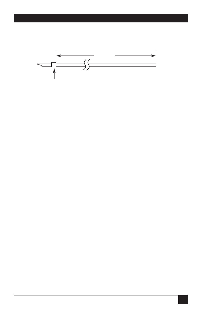
Mark this strip length from the end of the cable by wrapping the spot with a
piece of tape (see Figure 3-3).
Page 12
9
CHAPTER 3: Installation
Figure 3-3. Cable Strip Length.
Strip the cable according to the cable manufacturer’s instructions for removing
the sheath. Determine the cable central member and strength member yarn
lengths needed to secure the cable from the instructions provided with the
hardware.
If you are working with a grease or gel-filled water-blocked cable, use a d’Gel
wipe (or a tissue soaked with d’Gel liquid) to remove any flooding compound from
the buffer tubes.
Depending on the kit you’re using, measure 35 inches (88.9 cm) or 46 inches
(116.8 cm) of buffer tube from the end of the tubes. Use a permanent marker to
mark each tube at that spot.
CAUTION
To minimize the chance of breaking a fiber, follow the remaining steps
in this procedure one buffer tube at a time.
Tape
Strip length
Page 13

10
6- OR 12-BUFFER TUBE FANOUT KIT
3.2 Preparing the Buffer Tube
1. Tape the cable end to a work surface so that the marks on the buffer tubes
can reach the work surface edge (see Figure 3-4).
2. Select the first buffer tube. Use a buffer stripping tool to remove the buffer
tube back to the mark made in permanent marker.
3. Tape down the buffer tube that will receive the Buffer Tube Fanout. Make
sure 1 to 2 inches of tube overhang the work surface edge (see Figure 3-4).
Figure 3-4. Taping the Buffer Tube Fanout.
4. Wipe the filling compound from the exposed fibers with a d’Gel wipe (see
Figure 3-5). Use a clean, lint-free tissue to thoroughly dry each fiber.
Figure 3-5. Cleaning the Filling Compound from the Exposed Fibers.
5. Run a dry finger along each fiber to check for any filling compound residue.
If residue is present on the fiber, repeat step 4.
Buffer
tube
Tape
Tape
Page 14
11
CHAPTER 3: Installation
IMPORTANT
Make sure that the fibers are clean and dry. Any residue left on the fiber
will obstruct threading operations into the 900-µm assembly pieces.
6. Place the crimp tabs of the bottom piece of the Buffer Tube Fanout on the
end of the buffer tube. Press the tab with pliers to secure the Buffer Tube
Fanout bottom to the end of the tube (see Figure 3-6).
CAUTION
Be careful not to crush the tube. Crimp only until the tube begins to
deform. Spaces between the ends of the crimp tabs are normal for most
applications.
Check the crimp for effectiveness by pulling on and twisting the tube. The
tube should not move when pulling gently on it.
Figure 3-6. Securing the Buffer Tube Fanout Bottom to the End of the
Tube.
3.3 Threading the Fibers
1. Approximately 2 inches (5 cm) off to either side of the tube and Buffer Tube
Fanout bottom, use strapping tape to secure the plastic section of the 900-µm
assembly to the table’s edge as shown in Figure 3-7.
NOTE
The plastic section 900-µm assembly has color-coded legs and
corresponding numbers on its plastic housing. The number 1, or blue
tube should be on the front bottom right corner of the assembly.
2. Separate and untangle the number 1 (blue) fiber back to the point where it
exits the buffer tube.
Tabs
Page 15

12
6- OR 12-BUFFER TUBE FANOUT KIT
3. Carefully thread about three inches of the first fiber into the #1 slot of the
900-µm tube (see Figure 3-7).
Figure 3-7. Threading the Fiber.
4. Repeat steps 2 and 3 for the remaining fibers in sequential fiber order
(orange, green, brown, etc.). Work the threading process across the 900-µm
tube assembly in the proper order.
NOTE
Do not let any of the fibers cross each other during this threading
operation.
5. After all of the fibers have been inserted into the 900-µm tubes, gently push
the fibers into the tubes as a group until the fiber ends protrude from the
ends of the tubes.
1) Blue
2) Orange
3) Green
4) Brown
5) Slate
6) White
7) Red
8) Black
9) Yellow
10) Violet
11) Rose
12) Aqua
Top view
#1 fiber
Page 16

13
CHAPTER 3: Installation
6. Carefully pull the fibers out of the tube ends to take up most of the excess
length between the Buffer Tube Fanout body and the 900-µm assembly.
NOTE
Leave a small fiber loop between the Buffer Tube Fanout body and the
900-µm assembly to prevent fiber breakage during later steps in this
procedure (see Figure 3-8).
Figure 3-8. Leaving a Loop to Prevent Fiber Breakage.
7. Untape the 900-µm assembly from the table edge. Carefully slide the assembly
while gently pulling the bare fibers protruding from the 900-µm tube ends
until the assembly is above the fanout body (see Figure 3-9).
Figure 3-9. Pulling the Assembly.
At times the fibers will twist as a group when sliding the 900-µm assembly
toward the buffer tube. Rotate the 900-µm assembly opposite the direction of
twist until the fibers straighten out. Severe twists left in the fibers could
exhibit long term micro-bending effects on the fiber performance and add
loss.
Page 17

14
6- OR 12-BUFFER TUBE FANOUT KIT
NOTE
Because buffer tubes are semi-rigid, they require careful handling to
compensate for their “memory” and “springy” nature. Buffer tubes will
tend to quickly return to their original position after handling. Whenever
you use tape to anchor the tubes down, use care to control the tubes
when removing the tape.
8. Lower the insert section into the Buffer Tube Fanout body and press it into
place (see Figure 3-10).
Figure 3-10. Pressing the Insert Section into Place.
9. Align the top of the Buffer Tube Fanout body with the bottom and press
them together until the top snaps into place (see Figure 3-11).
Figure 3-11. Pressing the Bottom and Top Together.
10. Remove the tape from the buffer tube.
11. Separate another buffer tube and assemble the next Buffer Tube Fanout by
repeating steps 2 through 10.
Page 18

15
CHAPTER 3: Installation
NOTE
We recommend working with the tubes in sequential order to maintain
installation organization.
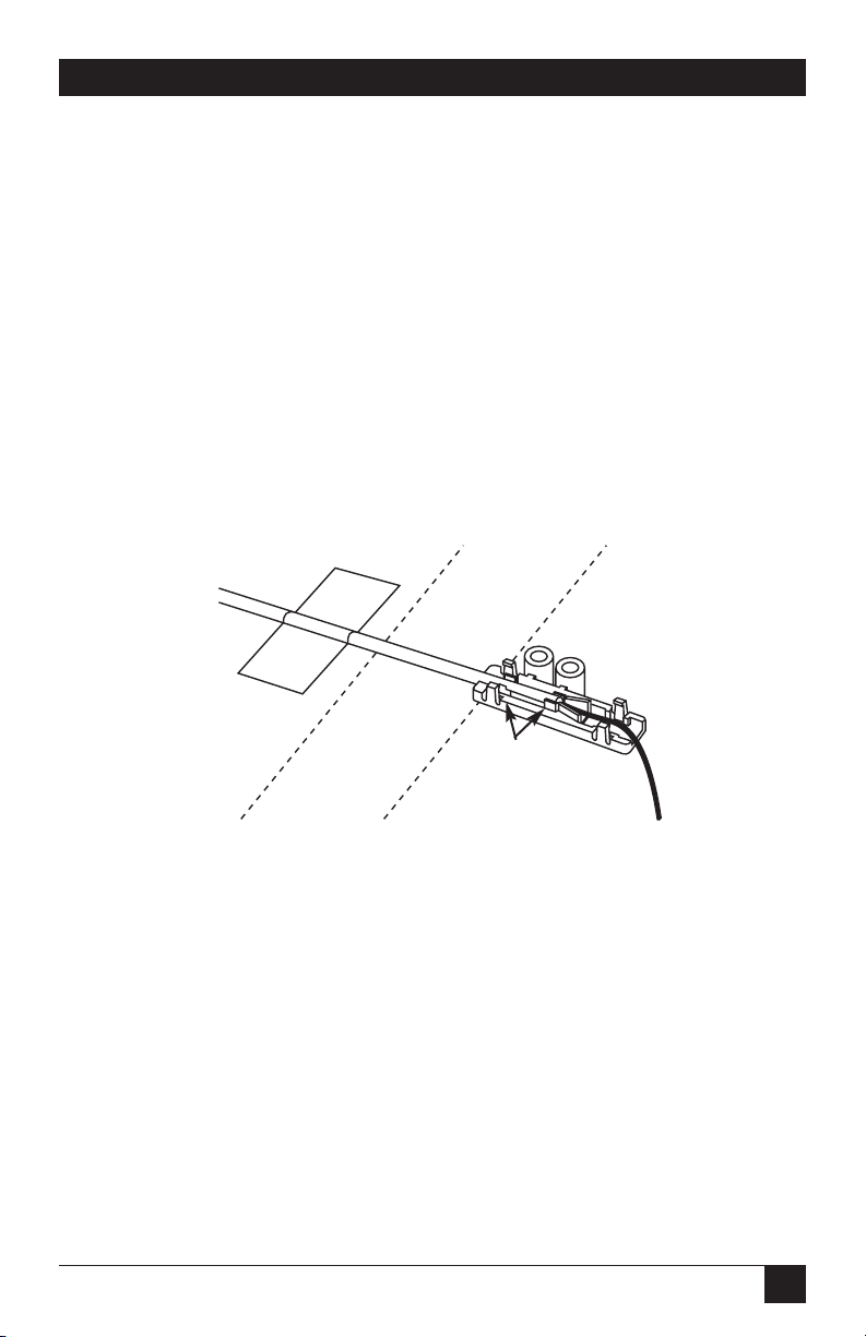
3.4 Marking the Buffer Tube Fanout
To aid in the identification and maintenance of the fanout assemblies, use
numbered wire markers. These markers can individually identify each Buffer Tube
Fanout with respect to its buffer tube number if the buffer tubes are not easily
distinguished (see Figure 3-12).
Figure 3-12. Marking the Buffer Tube Fanout.
3.5 Fiber Termination
1. Trim the excess fiber lengths to a length of 2 inches (5.1 cm) from the end of
the 900-µm tubing.
2. Terminate each fiber, working one Buffer Tube Fanout assembly at a time,
following the instructions provided with the connectors.
3. Test the connectors in accordance with standard test procedures or any
recommended test procedures supplied by the connector vendor.
Color-coded
900-µm tubes
Buffer tube
number
Page 19

16
6- OR 12-BUFFER TUBE FANOUT KIT
3.6 Installing the Buffer Tube Fanout into Hardware
1. You can either bolt or tape the Buffer Tube Fanout into pieces of hardware.
Refer to the instructions provided with the hardware you’re using to
determine the best method.
2. To route the Buffer Tube Fanout assembly into the hardware:
a. Hold the Buffer Tube Fanout body while grasping the buffer tube just outside
the assembly.
b. Carefully guide the Buffer Tube Fanout assembly into place, taking care to
prevent the buffer tube from kinking at the entrance to the Buffer Tube
Fanout body.
 Loading...