

Page 1
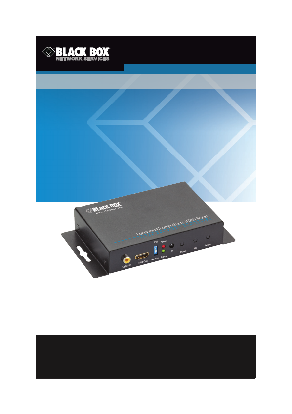
AVSC-VIDEO-HDMI
Component/Composite to HDMI Scaler
Converts Component/Composite signals
to HDMI compliant format.
Also supports S/PDIF audio through RCA into HDMI output.
Customer
Support
Information
Order to ll-free in the U.S.: Call 8 77-877- BBOX (outsid e U.S.
call 724 -746-55 00) • F REE techn ical sup port 24 h ours a day, 7 days
a week: C all 724-746-550 0 or fax 724-746- 0746 • Mailing addr ess:
Black Box Corporation, 100 0 Park Drive, Lawrence, PA 15055-1018
Web site: www.blackbox.com • E-mail: info@ blackbox.com
Page 2

Trademarks Used in this Manual
Trademarks Used in this Manual
Black Box and the Double Diamond log o are registered trademarks of
BB Technologies, Inc.
HDMI is a registered trademark of H DMI Licensing LLC.
Any other trademarks mentioned in this manual are acknowledged to be
the property of the trademark owners.
Page 2
724-746-5500 | blackbox.com
Page 3

FCC and IC RFI Statements/NOM Statement
FEDERAL COMMUNICATIONS COMMISSION AND INDUSTRY
CANADA RADIO FREQUENCY INTERFERENCE STATEMENTS
This equipment generates, uses, and can radiate radio-frequency energy, and if
not installed and used properly, that is, in stric t accordance with the manufacturer’s instructions, may cause inter ference to radio communication.
It has been tested and found to comply with the limit s for a Class A computing
device in accordance with the specifications in Subpart B of Part 15 of FCC rules,
which are designed to provide reasonable protection against such
interference when the equipment is operated in a commercial environment.
Operation of this equipment in a resid ential area is likely to cause interference, in
which case the user at his own expense will be required to take whatever measures may be necessar y to correc t the inter ference.
Changes or modifications not expressly approved by the party responsible
for compliance could void the user’s authority to operate the equipment.
This digital apparatus does not exceed the Class A limits for radio noise emis sion
from digital apparatus set out in the Radio Interference Regulation of Industry
Canada.
Le présent appareil numérique n’émet pas de bruits radioélec triques dépassant
les limites applicables aux appareils numériques de classe A prescrites dans le
Règlement sur le brouillage radioélectrique publié par Industrie Canada.
Normas Oficiales Mexicanas (NOM)
Electrical Safety Statement
INSTRUCCIONES DE SEGURIDAD
1. Todas las instrucciones de seguridad y operación deberán ser leídas antes
de que el aparato eléctrico sea operado.
2. L as instrucciones de seguridad y operación deberán ser guardadas para
referencia futura.
3. Todas las advertencias en el aparato eléctrico y en sus instrucciones de
operación deben ser respetadas.
4. Todas las instrucciones de operación y uso deben s er seguidas.
724-746-5500 | blackbox.com Page 3
Page 4

NOM Statement
5. El aparato elé ctrico no deberá ser usado cerca del agua — por ejemplo,
cerca
de la tina de baño, lavabo, sótano mojado o cerca de una alb erca, etc.
6. El aparato elé ctrico debe ser usado únicamente con carritos o pedestales
que sean recomendados por el fabricante.
7. El aparato elé ctrico debe ser montado a la pared o al techo sólo como sea
recomendado por el fabricante.
8. Servicio— El usuario no debe intentar dar ser vicio al equipo eléc trico más
allá a lo descrito en las instrucciones de operación. Todo otro servicio
deberá ser referido a personal de servicio calificado.
9. El aparato elé ctrico debe ser situado de tal manera que su posición no
interfiera su uso. La colocación del aparato eléctrico sobre una cama, sofá,
alfombra o sup erficie similar puede bloquea la ventilación, no se debe
colocar en libreros o gabinetes que impidan el flujo de aire por los orificios
de ventilación.
10. El equipo eléc trico deber ser situado fuera del alcance de fuentes de calor
como radiad ores, registros de calor, estufas u otros aparatos (incluyendo
amplificadores) que producen calor.
11. El aparato eléctrico deberá ser connec tado a una fuente de poder sólo
del tipo descrito en el instructivo de operación, o como s e indique en el
aparato.
12. Precaución debe ser tomada de tal manera que la tierra fisica y la
polarización del equipo no sea eliminada.
13. Los cables de la fuente de poder deben ser guiados de tal manera que no
sean pisados ni pellizcados por objetos colocados sobre o contra ellos,
poniendo particular atención a los contac tos y recept áculos donde salen
del aparato.
14. El equipo eléc trico debe ser limpiado únicamente de acuerdo a las
recomendaciones del fabricante.
15. En caso de exis tir, una antena externa deberá ser localizada lejos de las
lineas de energia.
16. El cable de corriente deberá ser desconectado del cuando el equipo no
sea usado por un largo periodo de tiempo.
Page 4
724-746-5500 | blackbox.com
Page 5

NOM Statement/Safety Notice
17. Cuidado debe ser tomado de tal manera que objectos liquidos no sean
derramados sobre la cubierta u orificios de ventilación.
18. Servicio por personal calificado deberá ser provisto cuando:
A: El cable de poder o el contacto ha sido dañado; u
B: Objectos han caído o líquido ha sido derramado dentro del aparato; o
C: El aparato ha sido expuesto a la lluvia; o
D: El aparato parece no operar normalmente o muestra un c ambio en su
desempeño; o
E: El aparato ha sido tirado o su cubier ta ha sido dañada.
Safety Notice
Please read and follow the safety instructions to protect yourself from possible
injury and to minimize the risk of damage to the unit.
• Follow all instructions and warnings marked on the unit.
• Do not attempt to service the unit yourself, except where explained in this
manual.
• Provide proper ventilation and air circulation and do not use near water.
• Keep objects that might damage the device away from it, and place the unit
on stable surfaces.
• Only use the power adapter, power cords, and connection cables designed for
the unit.
• Do not use liquid or aerosol cleaners to clean this unit. Always unplug the
power to the device before cleaning.
724-746-5500 | blackbox.com Page 5
Page 6

Table of Contents
Table of Contents
1. Specifications .........................................................................................7
2. Overview ................................................................................................9
2.1 Introduction ..................................................................................9
2.2 Features .........................................................................................9
2.3 What ’s Included ............................................................................9
2.4 Hardware Description .................................................................10
3. Connection Diagram ...........................................................................12
4. OSD Menu ...........................................................................................13
5. Operation .............................................................................................14
6. Troubleshooting .................................................................................. 22
6.1 Contac ting Black Box ................................................................. 22
6.2 Shipping and Packaging............................................................. 22
Page 6
724-746-5500 | blackbox.com
Page 7

Chapter 1: Specifications
1. Specifications
Approvals CE, FCC
Audio Support Stereo analog (48 KHz Fs sample rate)
Enclosure Metal wall mounting case with screws
ESD Protection Human body model:
Firmware Update via USB Por t
Frequency Bandwidth Input: 74.25 MHz;
Indicators (1) Red LED for Power;
Connectors Input: Component/Composite: (3) RCA
Environment Temperature Tolerance:
Power Power supply: 5 VDC, 2 A;
Dimensions 1.1"H x 3.6"W x 3.3"D (3 x 9.2 x 8.3 cm)
Weight 9.5 oz. (270 g)
±19 kV (air-gap discharge) and
±12 kV (contact discharge);
Core chipset: ±2 kV
Output: 165 MHz
(1) Green LED for V ideo Signal
female,
(2) audio (L/R );
Output: (1) HDMI;
Control and Power: (1) USB Mini B
Operating: 32 to 104° F (0 to 40° C);
Storage: - 4 to +140° F (-20 to + 60° C)
Relative Humidity: 20–90%, noncondensing
Consumption 5 Watts (ma x.)
NOTE: Resolution specifications are listed on the next page.
724-746-5500 | blackbox.com Page 7
Page 8

Chapter 1: Specifications
Resolution Specifications for AVSC-VIDEO-HDMI
Input Output
480i /576 i
480p /576 p
720p
1080i
1080p
720 x 480i @ 60 Hz
720 x 576i @ 50 Hz
720 x 480p @ 60 Hz
720 x 576p @ 50 Hz
1280 x 720p @ 60 Hz
1280 x 720p @ 59 Hz
1280 x 720p @ 50 Hz
1280 x 720p @ 30 Hz
1280 x 720p @ 25 Hz
1920 x 1080i @ 60 Hz
1920 x 1080i @ 59 Hz
1920 x 1080i @ 50 Hz
1920 x 1080p @ 50 Hz
1920 x 1080p @ 30 Hz
1920 x 1080p @ 25 Hz
1920 x 1080p @ 24 Hz
640 x 480p @ 60 Hz
640 x 480p @ 75 Hz
800 x 60 0p @ 60 Hz
800 x 60 0p @ 75 Hz
1024 x 768p @ 60 Hz
1024 x 768p @ 75 Hz
1280 x 1024p @ 60 Hz
1280 x 1024p @ 75 Hz
1360 x 768p @ 60 Hz
1366 x 768p @ 60 Hz
1400 x 1050p @ 60 Hz
1600 x 1200p @ 60 Hz
1440 x 90 0p @ 60 Hz
1440 x 90 0p @ 75 Hz
1680 x 1050p @ 60 Hz
1680 x 1050p RB
1920 x 1080p RB
1920 x 1200p RB
Page 8
724-746-5500 | blackbox.com
Page 9

Chapter 2: Overview
2. Overview
2.1 Introduction
Scalers work to conver t and scale a type of video /audio signal to another type
of video /audio signal. This enables you to use differently formatted video/audio
signals on differently formatted display screens. Scaling allows for changing
resolutions to increase quality or improve compatibility.
The Component/Composite to HDMI Scaler (AVSC-VIDEO-HDMI) converts
a component or CVBS signal to HDMI compliant format. It also supports S/ PDIF
audio through RCA into HDMI output. With this ex tra feature, us ers can
combine as ynchronous video and audio sources into an HDMI compliant A / V
signal.
2.2 Features
• Auto-detect function.
• Locking HDMI conne ctor.
• Locking power or optional USB powered.
• IR remote control
• Remote control via Mini-USB
• OSD control interface
• Maximum pixel rate: 165 MHz
• S/ PDIF input suppor ted
• Deinterlacer supported
• Supports noise reduction and video enhancement features
• Over/under scanning adjustable
• Video H / V mirror supported
• Active video area adjustment supported
• USB firmware upgradable for expanding compatibility
• Wallmount housing design for easy installation
2.3 What’s Included
• Component /Composite to HDMI Scaler
• 5-VDC, 2-A power supply unit
• This User's Manual
• Installation soft ware CD
724-746-5500 | blackbox.com Page 9
Page 10
Chapter 2: Overview
2.4 Hardware Description
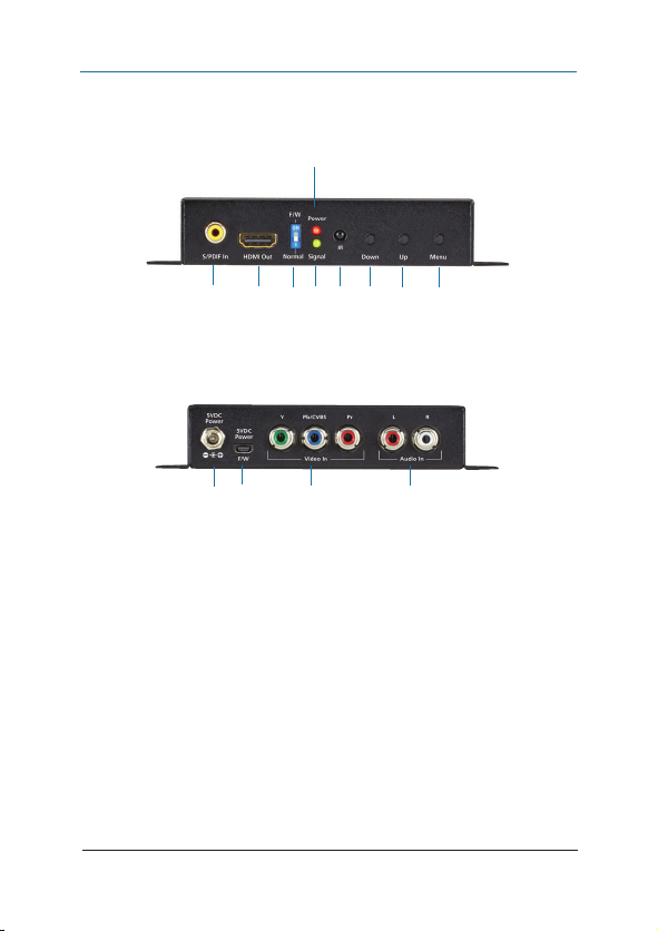
Figures 2-1 and 2-2 show the front and back panels of the scaler. Table 2-1
describes its components.
5
1 2 3 4 6 7 8 9
Figure 2-1. Front panel.
10 11 12 13
Figure 2-2. Back panel.
Page 10
724-746-5500 | blackbox.com
Page 11
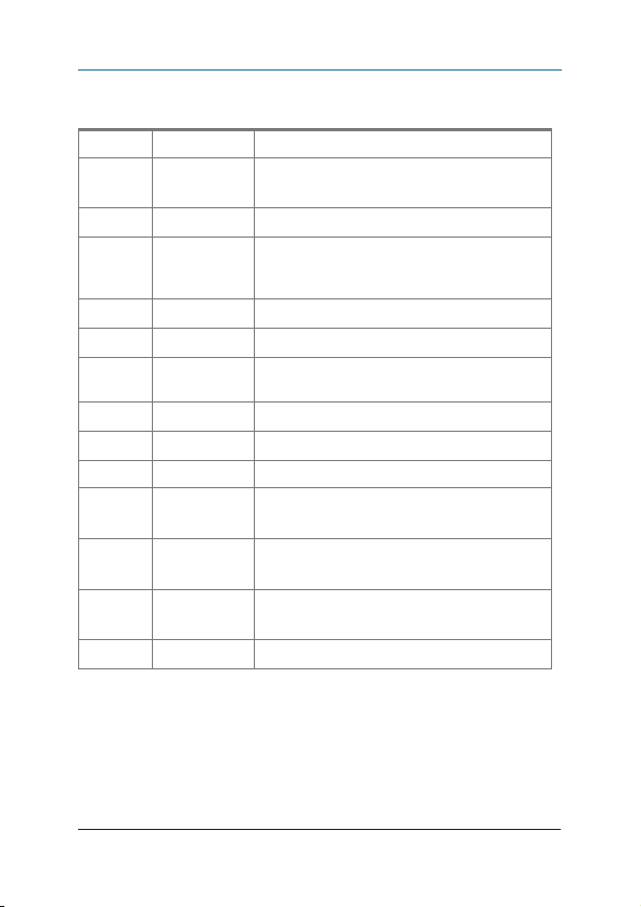
Table 2-1. Scaler components.
Number Component Description
1
2
3
4
5
6
7
8
9 Push button Menu/Enter button
10
11
12
13
S/ PDIF Audio
IN connector
HDMI out Connect to an H DMI input
DIP switch For firmware update:
LED indicator (1) Signal LED (green)
LED indicator (1) Power LED ( red)
IR sensor Used to receive the IR commands from IR
Push button Down button
Push button Up button
Interlocking
power jack
Mini-USB port • Used for firmware update
Component
Video YPbPr
Stereo Audio Connect to an audio input
Connects to digital S /P DIF audio source
ON (UP): firmware update mode;
OFF (DOWN): normal mode
remote
Connects to 5 VDC power supply unit
• Connects to 5 VDC power supply unit
• Connect to component input
• Pb input also acts as composite video input
Chapter 2: Overview
724-746-5500 | blackbox.com Page 11
Page 12
Chapter 3: Connection Diagram
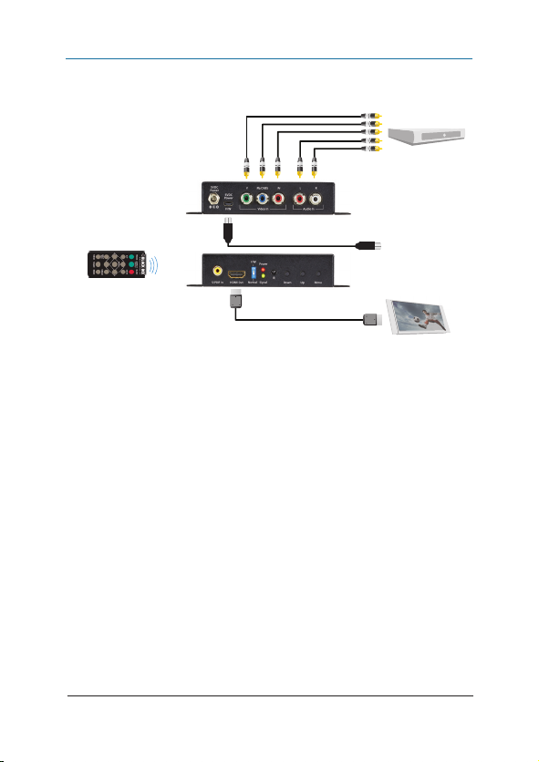
3. Connection Diagram
DVD player
Composite/Component
to HDMI Scaler
(AVSC-VIDEO-HDMI)
front (top)
back (bottom)
Analog au dio in
Flat panel display
Figure 3-1. Typical application.
Page 12
724-746-5500 | blackbox.com
Page 13
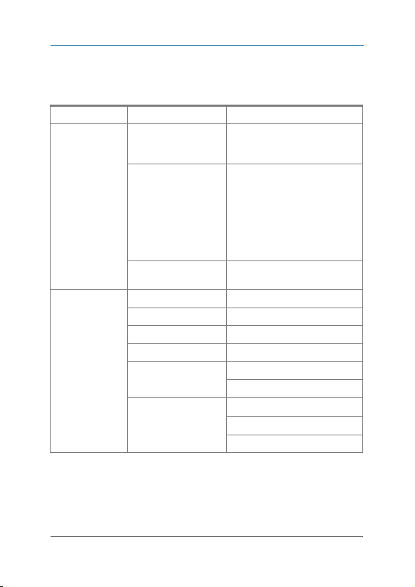
Chapter 4: OSD Menu
4. OSD Menu
Table 4-1. OSD menu.
Option Description Settings
1. Output Setup Output Mode RGB;
Default Pattern Disable (Default);
Audio Source Analog (Default);
2. Image Contrast 0–255 (Default 128)
Brightness 0 –255 (Default 128)
Saturation 0 –255 (Default 128)
Hue 0–255 (Default 128)
B/W Extension Off (Default)
Color Tone Off (Default)
YcbCr444;
Ycb Cr4 22
Window;
H-Ramp;
V-Ramp;
H-Gray;
V-Gray;
H-Color;
V-Color
S/PDIF
On
Skin
Green
724-746-5500 | blackbox.com Page 13
Page 14

Chapter 4: OSD Menu
Table 4-1 (continued). OSD menu.
Option Description Settings
2. Image
(continued)
3. Adjustment Under/Over Scan -50% –50% ( Default Off)
4. System In-Sync Info
Edge Enhance Typ. (Default);
Mid;
Max;
Off
Sharpness 0 –127 (Default 0)
Aspect Ratio 16:9 (Default);
4:3
H-Mirror Off (Default);
On
V-Mirror Off (Default);
On
Input H Adj -100 –100 (Defau lt 0 )
Input V Adj -50 –50 ( Default 0 )
Firmware Version
Factory Reset No (Default);
Yes
Page 14
724-746-5500 | blackbox.com
Page 15
5. Operation
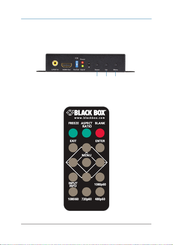
Method A: Push-in Button
See Figure 5-1.
Figure 5-1. Location of push but tons on the scaler.
Method B: IR Remote Control
Chapter 5: Operation
Down Up Menu
Figure 5-2. Remote control.
724-746-5500 | blackbox.com Page 15
Page 16

Chapter 5: Operation
Table 5-1. IR remote control functions.
Button Func tion
FREEZE Freeze video
ASPEC T R ATI O Aspect ratio change
BLANK Blank video
EXIT Exit OSD
ENTER Enter key
UP Up key
LEFT Lef t key
RIGHT Right key
DOWN Down key
MENU Menu on
INPUT INFO Source resolution information
1080p60 Select 1080p60 output resolution
1080i60 Selec t 1080i60 output resolution
720p60 Select 720p60 output resolution
480p60 Select 480p60 output resolution
Page 16
724-746-5500 | blackbox.com
Page 17
Chapter 5: Operation
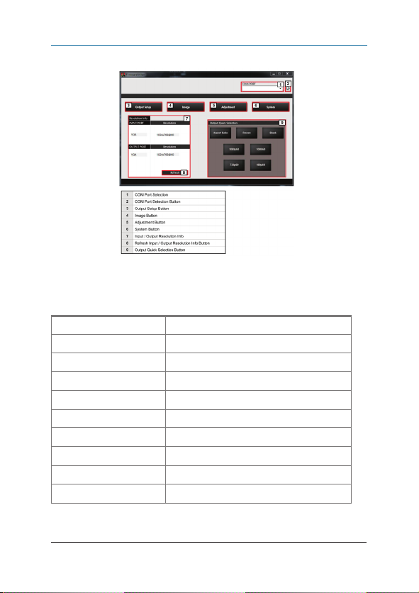
Method C: IR Remote Control through Mini- USB port
Figure 5-3.
Table 5-2. IR remote control through mini-USB port screen functions.
Number in Figure 5 -3 Function
1 COM Port Selection
2
3
4
5 Adjustment Button
6
7
8
9
COM Port Detection Button
Output Setup Button
Image Button
System Button
Input/Output Resolution Info
Refresh Input/Output Resolution Info Button
Output Quick Selection Button
724-746-5500 | blackbox.com Page 17
Page 18
Chapter 5: Operation
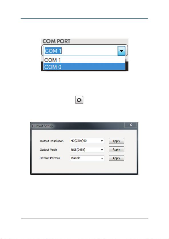
1. COM Port Selection
Please select the COM PORT application.
Figure 5-4. Select COM por t.
2. COM Por t Detection Button
Click on the cur ved-arrow button
3. Output Setup Button
Page 18
724-746-5500 | blackbox.com
to detect the COM PORT.
Figure 5-5.
Page 19
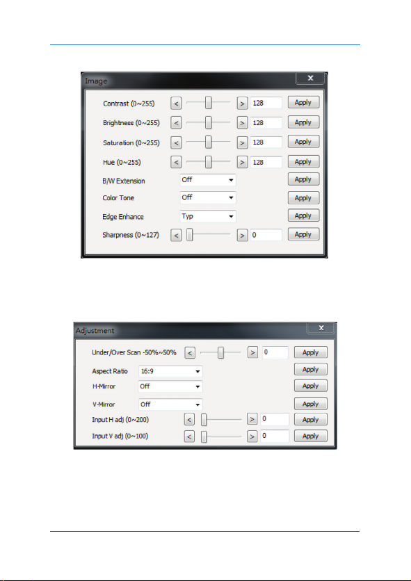
4. Image Button
5. Adjus tment Button
Chapter 5: Operation
Figure 5-6.
Fi g ure 5 -7.
724-746-5500 | blackbox.com Page 19
Page 20
Chapter 5: Operation
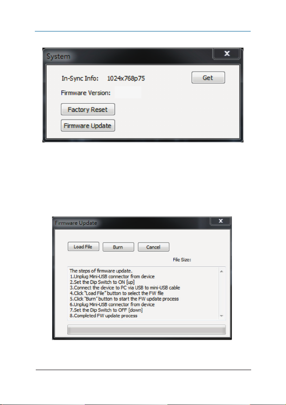
6. System Button
Figure 5-8. System screen.
1) In-Sync Info :
To view the current input resolution
2) Factory Reset Button
3) Firmware Update Button
Page 20
Figure 5-9. Firmware update screen.
724-746-5500 | blackbox.com
Page 21

Chapter 5: Operation
Follow these steps to update the firmware:
STEP A: Power off the device.
STEP B: Set the DIP switch to ON (UP) .
STEP C: Connec t the device to the PC via a USB to mini-USB cable.
STEP D: Click the FW Update button in the software.
STEP E: Click on the “Load File” button to select the firmware file.
STEP F: Click on the “Burn” button to start the firmware update process.
STEP G: Power on the device.
STEP H: Set the DI P switch to OFF (DOWN).
The firmware update process is complete.
7. I/O Port and Resolution Info
Displays the information about the I/O Port and the applied resolution.
8. Refresh But ton
Refreshes the status of the converter.
9. Output Quick Selection Button
Controls common functions for quick setting.
724-746-5500 | blackbox.com Page 21
Page 22

Chapter 6: Troubleshooting
6. Troubleshooting
6.1 Contacting Black Box
If you determine that your VGA to HDMI Scaler is malfunctioning, do not
attempt to alter or repair the unit. It contains no user-serviceable par ts. Contact
Black Box Technical Suppor t at 724-746-550 0 or [email protected].
Before you do, make a record of the history of the problem. We will be able to
provide more efficient and accurate assistance if you have a complete description, including:
• the nature and duration of the problem.
• when the problem occur s.
• the components involved in the problem.
• any particular application that, when used, appears to create the problem or
make it worse.
6.2 Shipping and Packaging
If you need to transpor t or ship your VGA to HDMI Scaler:
• Package it carefully. We recommend that you use the original container.
• If you are returning the unit, make sure you include every thing you received
with it. Before you ship for return or repair, contact Black Box to get a Return
Authorization (RA) number.
Page 22
724-746-5500 | blackbox.com
Page 23

NOTES
724-746-5500 | blackbox.com Page 23
Page 24

Chapter
Black Box Tech Support: FREE! Live. 24/7.
Tech support the
way it should be.
Great tech support is just 60 seconds away
at 724-746-5500 or blackbox.com.
About Black Box
Black Box provides an ex tensive range of networking and infrastructure
products. You’ll find ever ything from cabinets and rack s and power and surge
protection produc ts to media converters and Ethernet switches all supported
by free, live 24 /7 Tech support available in 60 se conds or less.
© Copyright 2014. Black Box Corporat ion. All rights reser ved.
AVSC-VIDEO-HDMI, version 1
724-746-5500 | blackbox.com
 Loading...