

Page 1
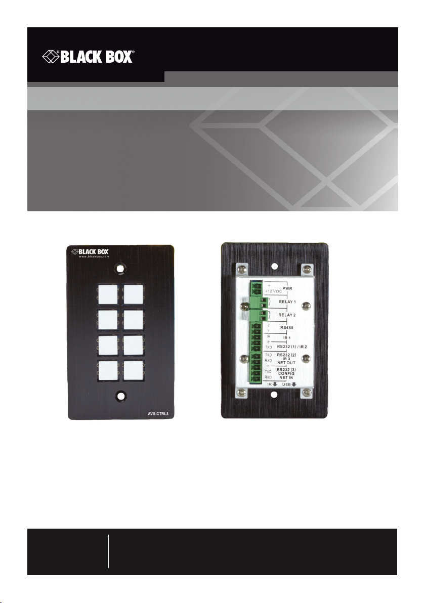
Wallplate Control Panel - 8-Button, RS-232
User Manual
Program buttons to send RS-232 and RS-485 commands to
control projectors, screens, and other third-party devices.
AVS-C TRL8
Customer
Support
Information
Order toll-free in the U.S. : Call 877-877-BBOX (outside U.S. call 724-746-5500)
FREE technical support 24 hours a day, 7 days a week: Call 724-746-550 0 or fax
724-746-0746 • www.blackbox.com • [email protected]
Page 2

Trademarks Used in this Manual
Trademarks Used in this Manual
Black Box and the Double Diamond logo are registered trademarks of
BB Technologies, Inc.
Any other trademarks mentioned in this manual are acknowledged to be
the property of the trademark owners.
Page 2
724-746-5500 | blackbox.com
Page 3

FCC and IC RFI Statements/NOM Statement
FEDERAL COMMUNICATIONS COMMISSION AND
INDUSTRY CANADA RADIO FREQUENCY INTERFERENCE STATEMENTS
This equipment generates, uses, and can radiate radio-frequency energy, and if
not installed and used properly, that is, in strict accordance with the
manufacturer’s instructions, may cause inter ference to radio communication.
It has been tested and found to comply with the limits for a Class A computing
device in accordance with the specifications in Subpart B of Part 15 of FCC rules,
which are designed to provide reasonable protection against such interference
when the equipment is operated in a commercial environment. Operation of
this equipment in a residential area is likely to cause interference, in which case
the user at his own expense will be required to take whatever measures may be
necessary to correct the interference.
Changes or modifications not expressly approved by the party responsible
for compliance could void the user’s authority to operate the equipment.
This digital apparatus does not exceed the Class A limits for radio noise
emis sion from digital apparatus set out in the Radio Interference Regulation
of Industry Canada.
Le présent appareil numérique n’émet pas de bruits radioélectriques dépassant les
limites applicables aux appareils numériques de la classe A prescrites dans le
Règlement sur le brouillage radioélectrique publié par Industrie Canada.
Normas Oficiales Mexicanas (NOM)
Electrical Safety Statement
INSTRUCCIONES DE SEGURIDAD
1. Todas las instrucciones de seguridad y operación deberán ser leídas antes
de que el aparato eléctrico sea operado.
2. Las instrucciones de seguridad y operación deberán ser guardadas para
referencia futura.
3. Todas las advertencias en el aparato eléctrico y en sus instrucciones de
operación deben ser respetadas.
4. Todas las instrucciones de operación y uso deben ser seguidas.
724-746-5500 | blackbox.com
Page 3
Page 4

NOM Statement
4. Todas las instrucciones de operación y uso deben ser seguidas.
5. El aparato eléctrico no deberá ser usado cerca del agua—por ejemplo,
cerca de la tina de baño, lavabo, sótano mojado o cerca de una alberca,
etc..
6. El aparato eléctrico debe ser usado únicamente con carritos o pedestales
que sean recomendados por el fabricante.
7. El aparato eléctrico debe ser montado a la pared o al techo sólo como sea
recomendado por el fabricante.
8. Servicio—El usuario no debe intentar dar servicio al equipo eléctrico más allá
lo descrito en las instrucciones de operación. Todo otro servicio deberá ser
referido a personal de servicio calificado.
9. El aparato eléctrico debe ser situado de tal manera que su posición no
interfiera su uso. La colocación del aparato eléctrico sobre una cama, sofá,
alfombra o superficie similar puede bloquea la ventilación, no se debe
colocar en libreros o gabinetes que impidan el flujo de aire por los orificios
de ventilación.
10. El equipo eléctrico deber ser situado fuera del alcance de fuentes de calor
como radiadores, registros de calor, estufas u otros aparatos (incluyendo
amplificadores) que producen calor.
11. El aparato eléctrico deberá ser connectado a una fuente de poder sólo del
tipo descrito en el instructivo de operación, o como se indique en el
aparato.
12. Precaución debe ser tomada de tal manera que la tierra fisica y la
polarización del equipo no sea eliminada.
13. Los cables de la fuente de poder deben ser guiados de tal manera que no
sean pisados ni pellizcados por objetos colocados sobre o contra ellos,
poniendo particular atención a los contactos y receptáculos donde salen
del aparato.
14. El equipo eléctrico debe ser limpiado únicamente de acuerdo a las
recomendaciones del fabricante.
15. En caso de existir, una antena externa deberá ser localizada lejos de las
lineas de energia.
Page 4
724-746-5500 | blackbox.com
Page 5

NOM Statement
16. El cable de corriente deberá ser desconectado del cuando el equipo no sea
usado por un largo periodo de tiempo.
17. Cuidado debe ser tomado de tal manera que objectos liquidos no sean
derramados sobre la cubierta u orificios de ventilación.
18. Servicio por personal calificado deberá ser provisto cuando:
A: El cable de poder o el contacto ha sido dañado; u
B: Objectos han caído o líquido ha sido derramado dentro del aparato; o
C: El aparato ha sido expuesto a la lluvia; o
D: El aparato parece no operar normalmente o muestra un cambio en su
desempeño; o
E: El aparato ha sido tirado o su cubierta ha sido dañada.
724-746-5500 | blackbox.com
Page 5
Page 6

Safety Precautions
Safety Precautions
For reliable operation of the equipment and personnel safety, follow the guidelines
below for installation, use, and maintenance of the device.
1. The system must be grounded properly. Do not use two-blade plugs and ensure the
alternating power supply ranges from 100 to 240 VAC and 50 to 60 Hz.
2. Do not put the control panel in an environment that is not within the its temperature
tolerance.
3. Because the switch’s power generates heat when running, be sure the working
environment is properly ventilated to avoid damage caused by equipment
overheating.
4. Turn off the general power switch in humid weather or when the control panel will
be left unused for long time.
5. Before operating, be sure that the alternating current wire is pulled out of the power
supply.
6. NEVER open the casing of the equipment, DO NOT repair it on your own. This might
be harmful to persons or the equipment.
7. DO NOT splash any liquids on or around the equipment.
Page 6
724-746-5500 | blackbox.com
Page 7

Table of Contents
Table of Contents
1. Specifications ..............................................................................................8
2. Overview ..................................................................................................... 9
2.1 Introduction ..................................................................................... 9
2.2 Features ........................................................................................... 9
2.3 What's Included .............................................................................. 10
2.4 Hardware Description .....................................................................10
2.4.1 Front Panel ............................................................................. 11
2.4.2 Side Panel .............................................................................. 11
2.4.3 Back Panel .............................................................................12
2.5 Typical Application .......................................................................... 14
3. Programming and Looping ......................................................................... 15
4. System Operation ....................................................................................... 17
4.1 Installing the USB Driver ..................................................................17
4.2 Software Programming ................................................................... 17
4.2.1 Main Menu ............................................................................ 18
4.2.2 Panel/Key Setting ..................................................................20
4.2.3 Action List.............................................................................. 23
4.2.4 Event Setting .........................................................................23
4.2.5 Event List ............................................................................... 32
4.3 Front-Panel Buttons ........................................................................33
4. Troubleshooting and Maintenance .............................................................34
724-746-5500 | blackbox.com
Page 7
Page 8

Chapter 1: Specifications
1. Specifications
Interfaces
Programming Port USB or RS-232
Output Ports (3) RS-232, (1) RS-485, (3) Infrared, (2) Relay
Serial Control Port RS-232
Baud Rate and Protocol 9600 baud, 8 data bits, 1 stop bit, no parity
Frequency Response 20 Hz - 20 kHz
Environmental
Temperature Tolerance -4 to +158° F (-20 to +70° C)
Humidity 10 to 90%
Power
Power Supply 100 VAC–240 VAC, 50/60 Hz
Consumption 1 W
Physical
Dimensions 1.1"H x 2.8"W x 4.5"D (2.8 x 7 x 11.4 cm)
Weight 0.33 lb (0.15 kg)
Page 8
724-746-5500 | blackbox.com
Page 9

Chapter 2: Overview
2. Overview
2.1 Introduction
together. The Wallplate Control Panel has (3) built-in programmable RS-232 connectors,
(1) RS-485 connector, (3) Infrared (IR) connectors, (2) Relay connectors, and (1) mini USB
connector.
NOTE: RS-232 port 1 and IR port 2 share the same port and cannot be used at the
same time. RS-232 port 2 and IR port 3 share the same port and cannot be used
at the same time. The Programmable Control Panel can fully control the
compatible switches, as well as third-party devices such as projectors, screens,
etc. Use the device for presentations in showrooms, classrooms, and
boardrooms.
2.2 Features
• Every button can be programmed to send bi-directional RS-232 and RS-485 commands simultaneously to control third-party devices.
• Every button can be programmed to send the infrared code and control the relay to
simultaneously control the third-party devices.
• Every button has the built in infrared code, RS-232 code learning function, and baudrate setting.
• ID looping function. Up to 10 Wallplate Control Panels can be looped and controlled
together via ID.
• Program via a USB or RS-232 port to work with PC software (Black Box Control).
• Has crystal and backlit buttons with user-friendly customizable changeable labels.
• You can control the brightness of the backlight.
• Dimensions: 1.1"H x 2.8"W x 4.5"D (2.8 x 7 x 11.4 cm).
724-746-5500 | blackbox.com
Page 9
Page 10

Chapter 2: Overview
2.3 What’s Included
Your package should include the following items. If anything is missing or damaged,
Your package should contain the following items. If anything is missing or damaged,
contact Black Box Technical Support
at 724-746-5500 or [email protected].
• (1) Wallplate Control Panel - 8-Button, RS-232
• (3) pluggable terminal blocks
• (1) mini USB converter cable
• (2) IR emitters
• (8) button caps
• (1) button label
• (1) transparent paper table
• (1) 12-VDC power adapter
To download this user manual from our Web site:
1. Go to www.blackbox.com
2. Enter the part number (AVS-CTRL8) in the search box:
3. Click on the “Resources” tab on the product page, and select the document you
wish to download.
If you have any trouble accessing the Black Box site to download the manual, you can
contact our Technical Support at 724-746-5500 or [email protected].
2.4 Hardware Description
Figures 2-1 through 2-3 show the front, side, and back panels of the AVS-CTRL8.
Tables 2-1 ans 2-2 describes its components.
Page 10
724-746-5500 | blackbox.com
Page 11
Chapter 2: Overview
2.4.1 Front Panel
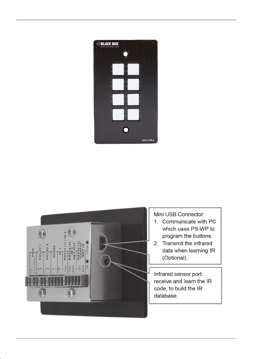
Figure 2-1. Front panel of the AVS-CTRL8.
The front panel contains (8) crystal and luminescent programmable buttons. Every
button can be programmed with the Black Box Control software.
2.4.2 Side Panel
Figure 2-2. Connectors on the side panel of the AVS-CTRL8.
724-746-5500 | blackbox.com
Page 11
Page 12
Chapter 2: Overview
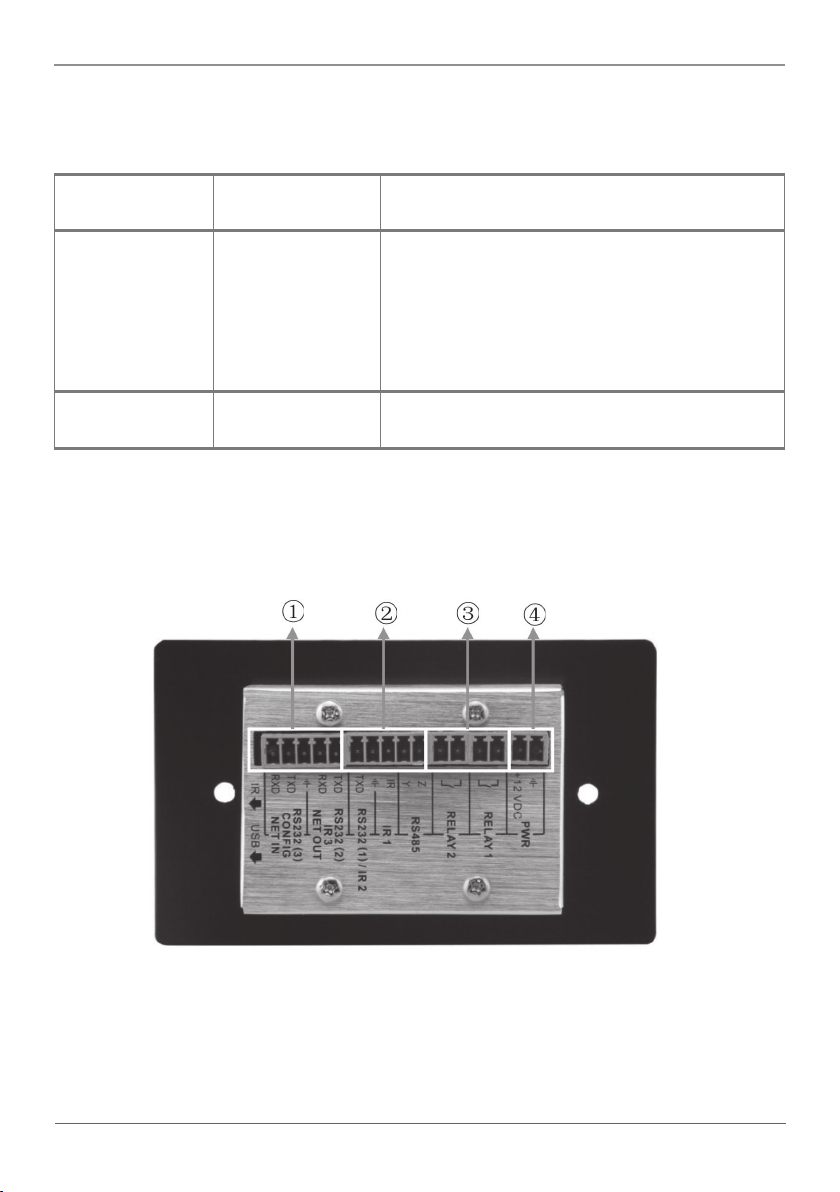
Table 2-1. SIde panel components.
Number in
Figure 2-2
1 Mini USB
2 Infrared sensor
NOTE: When using the USB port to program the AVS-CTRL-8 buttons, the available COM
port number should not be more than 10.
Component Description
This connector has two functions:
connector
port
1. Communicate with the PC that uses Black
Box Control to program the
buttons.
2. Transmit the infrared data when learning IR
(optional).
Receive and learn the IR code to build the IR
database.
2.4.3 Back Panel
Figure 2-3. Back panel.
The AVS-CTRL8 has various ports on the rear panel, including a Looping port, RS-232
port, RS-485 port, IR port, Relay port, and Power port as described in the table on the
next page.
Page 12
724-746-5500 | blackbox.com
Page 13
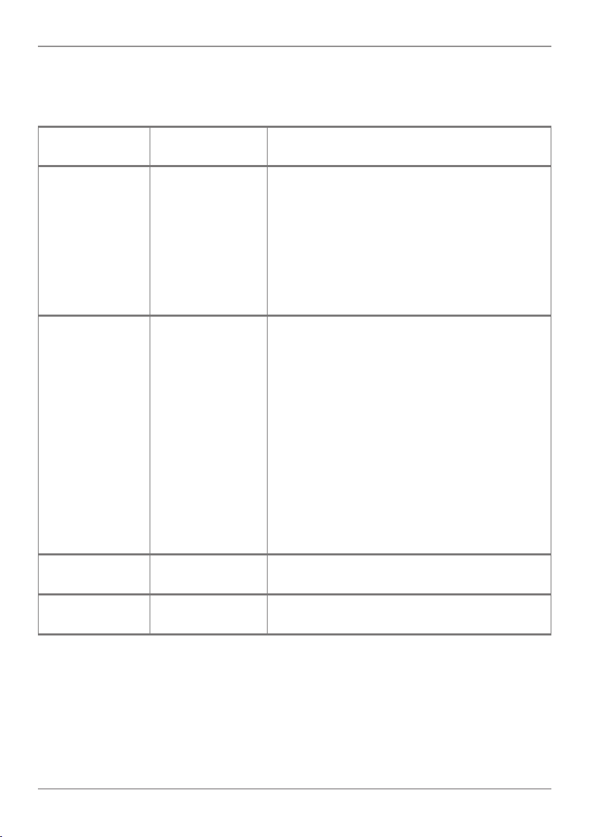
Table 2-2. Back panel components.
Chapter 2: Overview
Number in
Figure 2-3
1 RS-232 port 2/
2 RS-232 port 1/
3 Low-Voltage relay
4 Power connector 12-VDC. Be sure that the “+” and “-” are
Component Description
Use this port to control other devices or for
IR port 3
IR port 2, IR port
1, and RS-485
port
ports
looping output. RS-232 port 2 and IR port 3
share the same port; their use depends on the
setting of Black Box Control software. The
other part of the port is RS-232 port 3. It can
be used to control other devices or for looping
output, or connect with a PC. These two ports
share the same grounding.
a. RS-232 (1)/IR2: share the same port, its
detailed use depends on the Black Box
Control setting. When used as RS-232, the
port transmits data but does not receive
data.
b. IR1: To control other devices, program this
port via Black Box Control
software.
c. RS-485: You can program the RS-485 port
with commands to control the device with
the RS-485 port. The command for RS-485
is the same as RS-232 port 1.
Set the relay on/off via Black Box Control software.
never mixed or connected incorrectly.
724-746-5500 | blackbox.com
Page 13
Page 14
Chapter 2: Overview
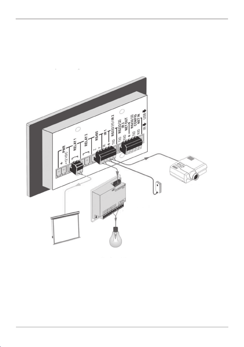
2.5 Typical Application
The Wallplate Control Panel can activate different ports at one time. Every button can
send RS-232 and RS-485 commands, IR codes, and control the relay at the same time.
Page 14
Screen control
IR
transmitter
Power dimmer
Lighting system
power control
Figure 2-3. System Diagram.
724-746-5500 | blackbox.com
Projector
RS-232 device
Page 15
Chapter 3: Programming and Looping
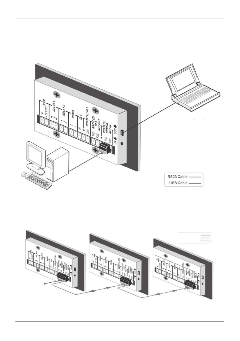
3. Programming and Looping
Tshe Wallplate Control Panel can be connected to the computer for programming, to
set the functions of every button. You can connect it via USB or RS-232, and it works
with the Black Box Control software.
Laptop
PC
Figure 3-1. Programming Connection
Several AVS-CTRL8 units can also be looped to create a system that controls more
devices. It is looped using the RS-232 setting.
Third AVS-CTRL8
Second AVS-CTRL8
First AVS-CTRL8
First AVS-CTRL8
Looping
to next
AVS-CTRL8
Third AVS-CTRL8
Second AVS-CTRL8
Figure 3-2. Several Looping Wallplates Control Panels connected.
724-746-5500 | blackbox.com
Page 15
Page 16
Chapter 3: Programming and Looping
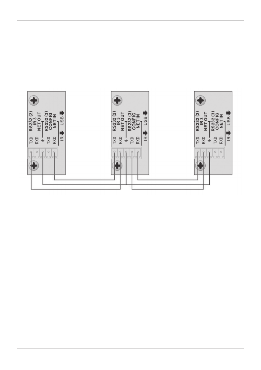
After you connect the Wallplate Control Panel as above, set the ID of each Wallplate
Control Panel via Black Box Control software. The ID number ranges from 01 to 99,
and it also contains the class of the Wallplate Control Panel in the loop. Set different
Wallplate Control Panel units to different IDs. Once you make these connections, you
can set the control modes via Black Box Control software. For connection details, see
the picture on the next page.
Last class…
Second class
Figure 3-3. Detailed looping connections.
NOTE: Up to 99 Wallplate Control Panels can be looped within one system, but for
normal interaction, we recommend looping a maximum of 10 Wallplate Control
Panels in one system.
Page 16
724-746-5500 | blackbox.com
Page 17
Chapter 4: System Operation
4. System Operation
4.1 USB Driver Installation
You can download the Black Box Control software from www.blackbox.com.
The Black Box Control software can run directly without installation. When you connect
the Wallplate Control Panel with a PC via USB, you might need to install the USB driver.
4.2 Software Programming
Use the Black Box Control software to easily set every button on the AVS-CTRL8.
After connecting the Wallplate Control Panel with PC via USB or RS-232, you can open
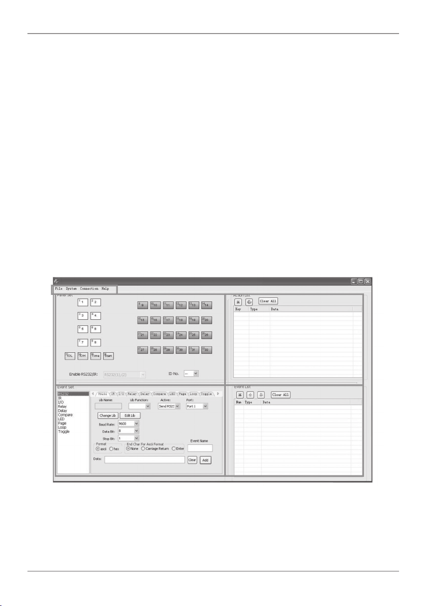
the Black Box Control software to program the buttons. The main window of Black Box
Control software has five parts: main menu, panel (button) setting, event setting, action
list, and event list. In this manual, we will show the uses of all functions. The main
window of Black Box Control software is shown below.
Figure 4-1. Main window.
We will introduce the configurations one-by-one.
724-746-5500 | blackbox.com
Page 17
Page 18
Chapter 4: System Operation
4.2.1 Main Menu
The main menu includes file management, system model, connection type, and help.
1. File management: Open/Save/Save as a configuration. After programming, you can
save the configuration to a file, so that you can use the same configuration next time.
2. System model: The diagram below shows the main menu.
Figure 4-2. Main menu.
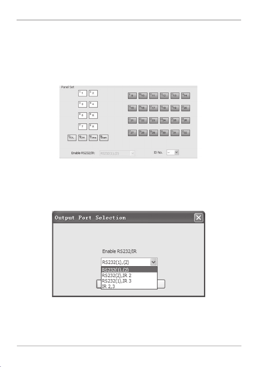
NOTE: When selecting the Wallplate Control Panel model, the “Output Port Selection”
dialog box will appear. You can select different RS and IR types, depending on
the uses of the two shared ports.
Figure 4-3. Output Port Selection dialog box.
The output port set in Black Box Control software corresponds to the port used in
Wallplate Control Panel. There are four output types, as shown below (“√” means the
port is available):.
Page 18
724-746-5500 | blackbox.com
Page 19
Chapter 4: System Operation
Table 4-1. Output port of AVS-CTRL8.
Output port
IR1 RS-232 (1) IR2 RS-232 (2) IR3 RS-232 (3) RS-485
of AVS-CTRL8
Output mode of Black Box Control software
RS-232(1) (2) √ √ √ √ √
RS-232(2), IR2 √ √ √ √
RS-232(1), IR3 √ √ √ √ √
IR2, 3 √ √ √ √
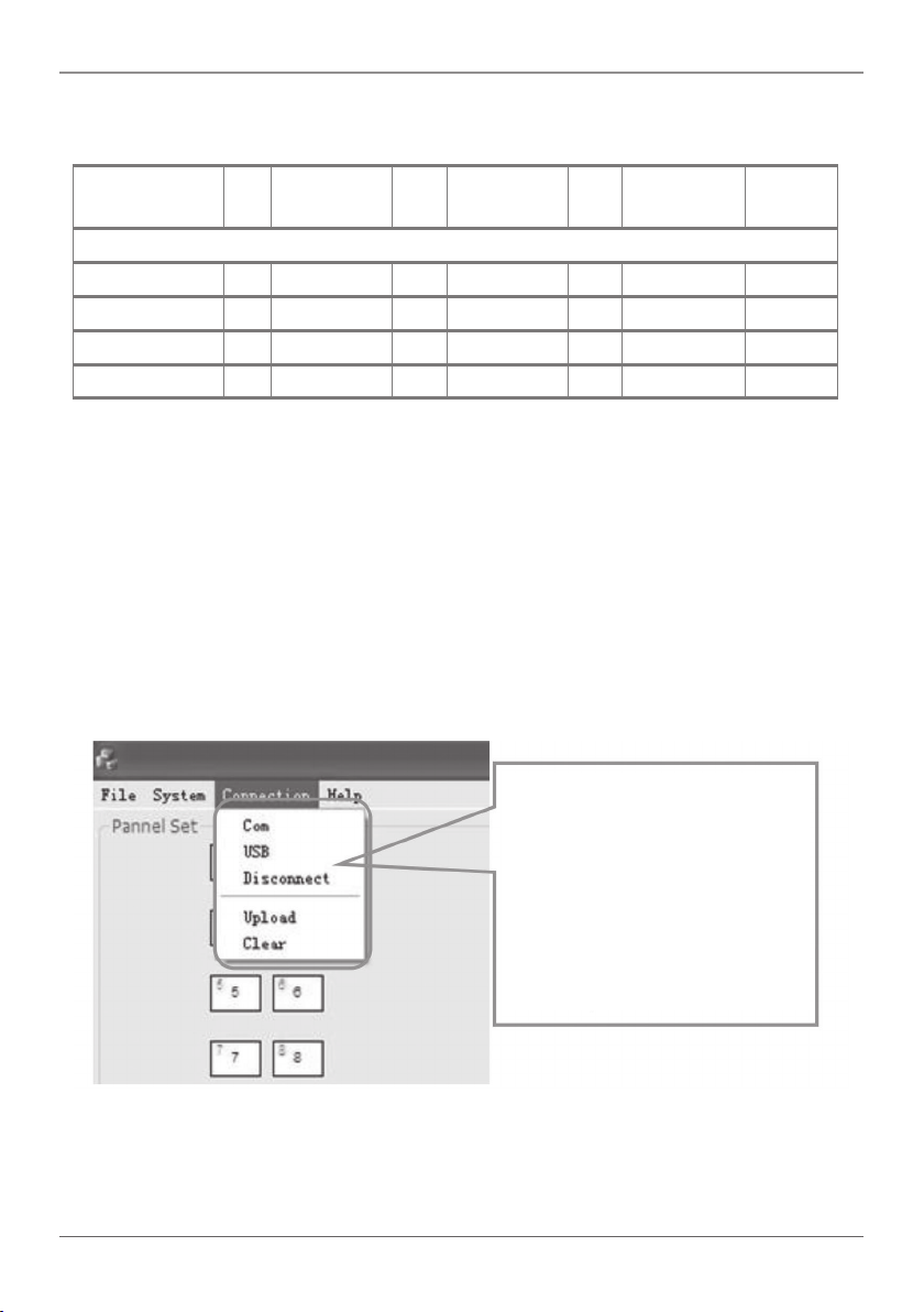
3. Connection type: follow the instructions in the picture below:
1. COM port, connected via serial port.
2. USB, connected via mini USB port.
3. Disconnect (disconnect the connection).
4. Upload: Upload the programmed data to the AVS-CTRL8. The old data will be
cleared.
5. Clear: Clear the data in the AVS-CTRL8.
1. COM port, connected via serial port.
2. USB, connected via mini USB port.
3. Disconnect (disconnect the connection).
4. Upload: Upload the programmed data
to the AVS-CTRL8. The old data will
be cleared.
5. Clear: Clear the data in the
AVS-CTRL8.
Figure 4-4. Connection window.
724-746-5500 | blackbox.com
Page 19
Page 20
Chapter 4: System Operation
The functions of the Wallplate Control Panel buttons will be available only after the
programmed data is uploaded successfully.
4. Help: Show the Black Box Control software's information.
4.2.2 Panel/Key Setting
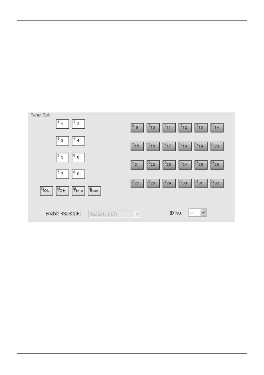
There are three different colors of keys on the Black Box Control software panel. Add a
key action to action list, then add events to this action; enabling this action will execute
the events. The example below introduces the uses of different buttons:
Page 20
Figure 4-5. Panel Set screen.
724-746-5500 | blackbox.com
Page 21
Chapter 4: System Operation
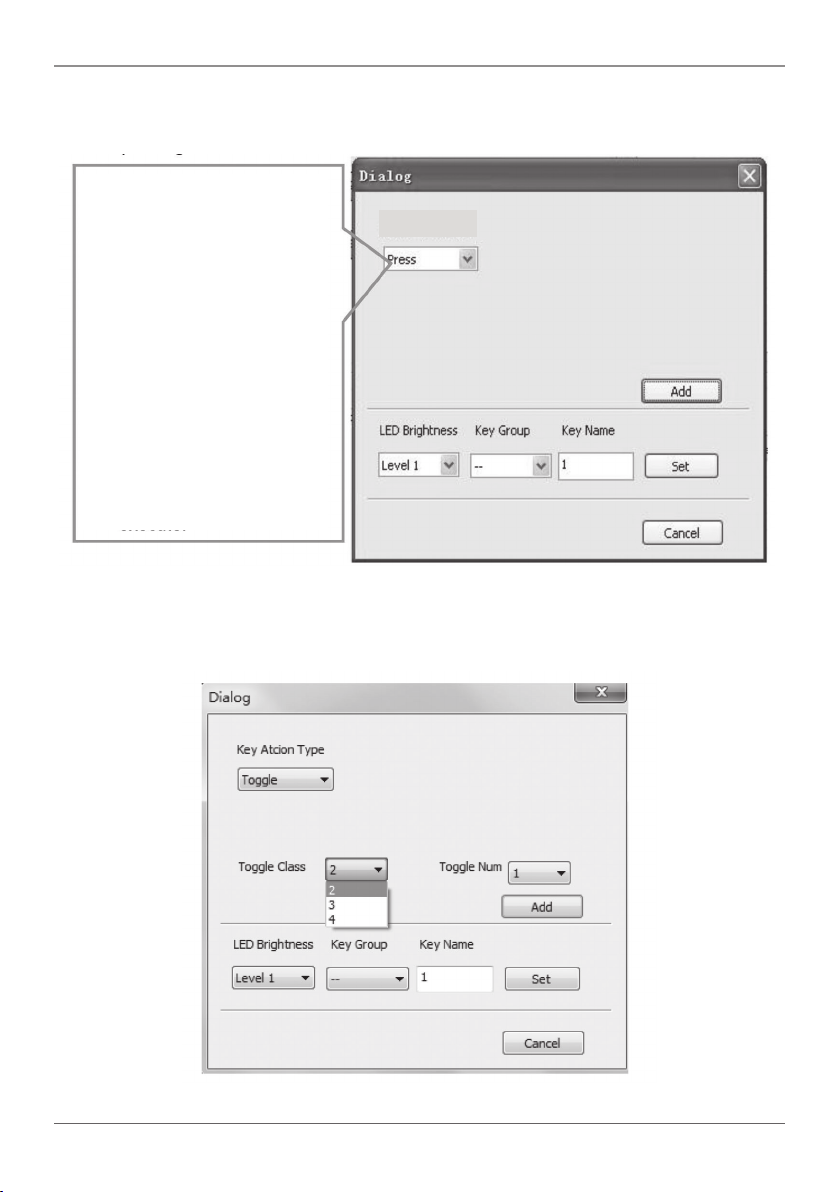
1. White keys: keys 1–8, correspond to the buttons on Wallplate Control Panel. Click
the key, and the dialog below will appear:
Key Action Type:
1. Pressing the button selects
Execute events.
2. Releasing the button
executes the action.
3. For built-in actions that
need to be switched by
other buttons, press to
execute.
4. Toggle between built-in
actions.
Figure 4-6. Wallplate Control Panel buttons dialog box.
Key Action Type
When you select “Toggle,” the setting interface is as shown next:
Figure 4-7. Setting interface.
724-746-5500 | blackbox.com
Page 21
Page 22
Chapter 4: System Operation
The toggle class is the action loop class and depends on the numbers of looped
actions. When the class is 2, there are two actions that you can toggle.
2. Blue Keys: Keys 9–32, all virtual keys, are used in the loop function. When you use
the loop function, you must set the ID, which can range from 1 to 99. Press “Add”
to add the button to the action list.
3. Yellow Keys: Keys 33–36, all are virtual keys. Key 33 and 34 are for I/O control,
which is not supported with Wallplate Control Panel. Key 36 is a start action; if you
add events to this action, when the Wallplate Control Panel power is on, it will
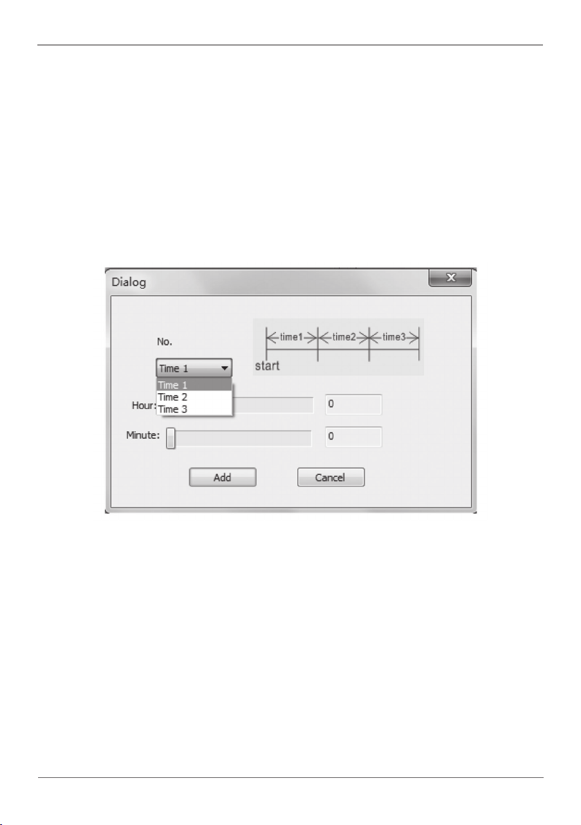
execute the events in this action. Key 35 is a delay button, and you can set three
time slots.
Figure 4-8. Dialog box.
This is the time that elapses after the Wallplate Control Panel starts. When set to time1,
Wallplate Control Panel will execute the events in time1. Next, set time2 and time3.
Example: Set time1 to 5 minutes, and time2 to 3 minutes, add event1 to time1 and
event2 to time2. When the unit starts, it will execute event1 after 5 minutes, and then
execute event2 after 8 minutes.
Page 22
724-746-5500 | blackbox.com
Page 23
Chapter 4: System Operation
4.2.3 Action List
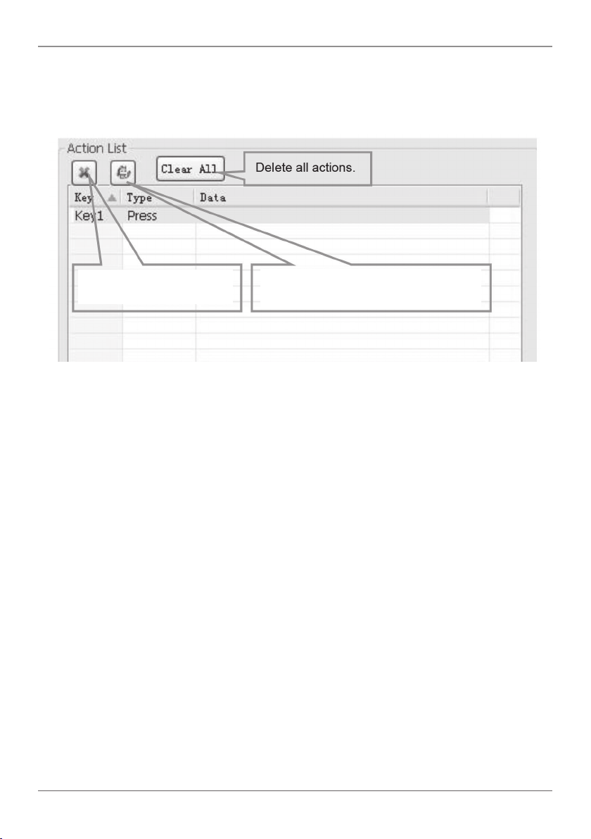
Action list shows all the set actions. An available action must be added to the list. The
action list is shown in the picture below:
Delete a selected action.
Figure 4-9. Action List screen.
Refresh screen. Delete all actions
without events.
4.2.4 Event Setting
Event settings include RS-232, IR, I/O, Relay, Delay, Compare, LED, Page, Loop, and
Toggle. Before you set events, you must add an action. The following introduction will
show you how to set each event:
• RS-232 Setting
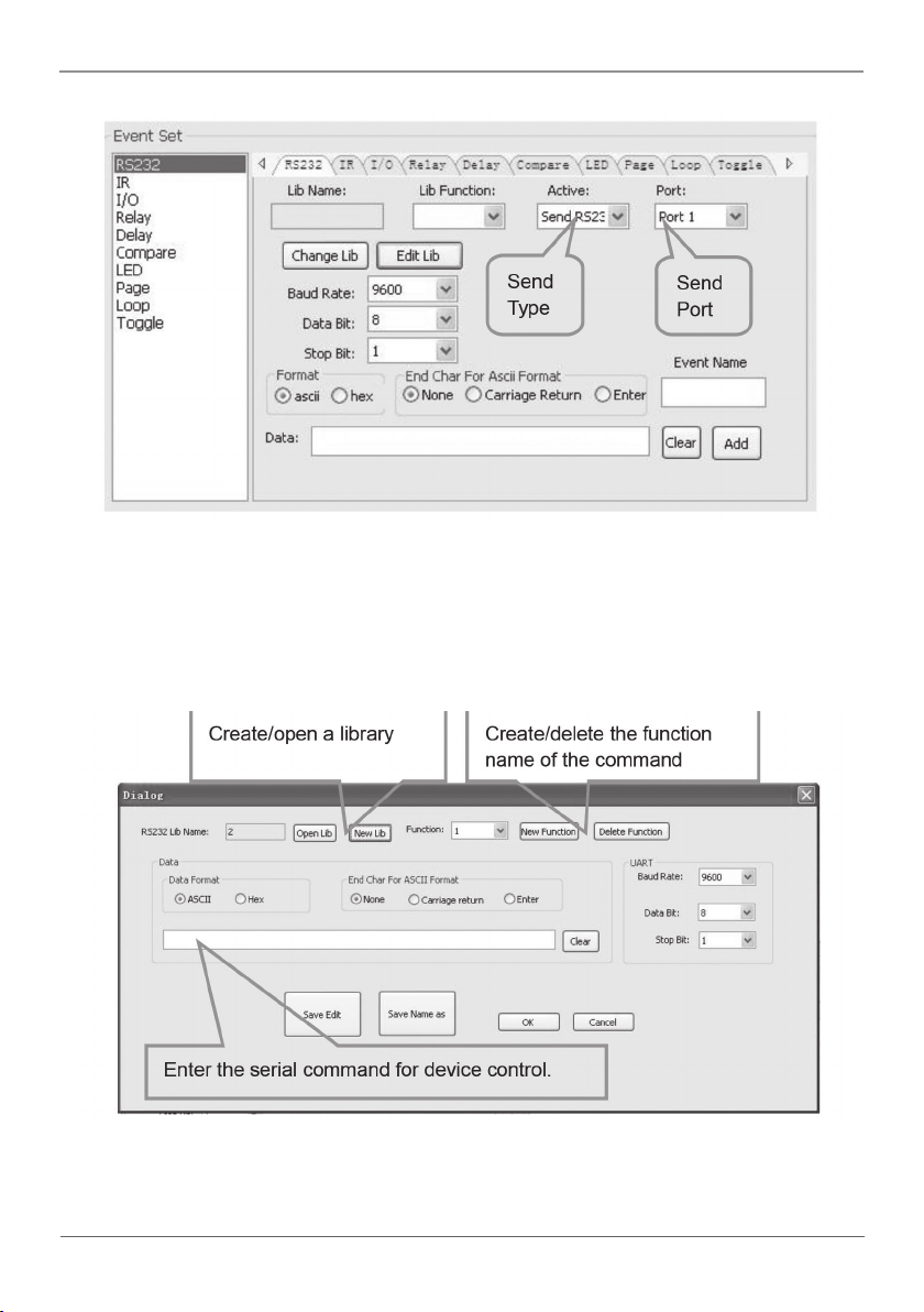
Use this item to set the Wallplate Control Panel’s serial ports parameters. Click
“RS-232,” and the following screen will appear.
724-746-5500 | blackbox.com
Page 23
Page 24
Chapter 4: System Operation
Figure 4-10. Event setting screen.
1. You can directly enter RS-232 data or select it from the from library. Click “Change
Lib” to select a library file and open it. Click “Edit Lib” to create or edit a library file
as below:
Figure 4-11. Library screen.
NOTE: When you finish editing, remember to save the setting and then press “OK.”
Page 24
724-746-5500 | blackbox.com
Page 25
Chapter 4: System Operation
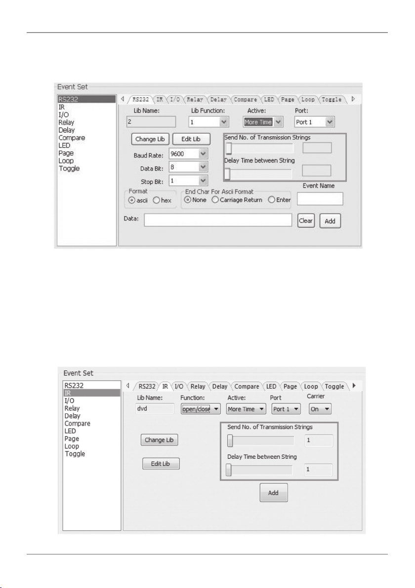
2. There are two send types: send once and send more times. When you select “more
times,” you can set the send times and the delay between times.
Figure 4-12. Send screen.
3. The send port must be selected the same as the model setting; otherwise, the event
cannot be added.
4. Users can set the event name. This is an optional function.
• IR Setting
Use this item to set the Wallplate Control Panel’s IR ports' parameters. Click “IR,” and
the screen below will appear.
Figure 4-13. IR set screen.
724-746-5500 | blackbox.com
Page 25
Page 26
Chapter 4: System Operation
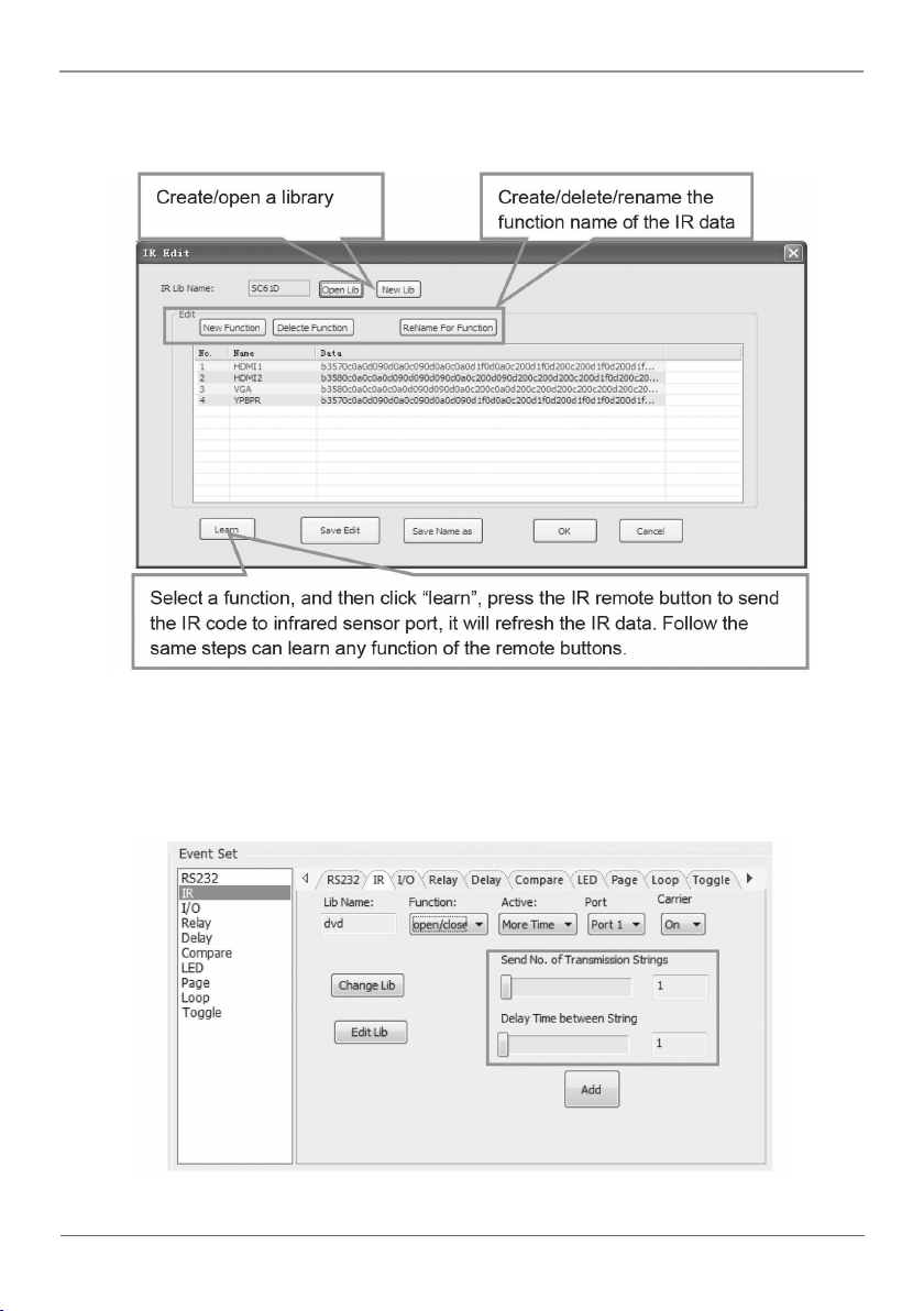
1. Select the IR data from the library. Click “Change Lib” to select a library file and open
it. Click “Edit Lib” to create or edit a library file.
Figure 4-14. Edit Library screen.
NOTE: When you finish editing, save the editing and press “OK.”
2. There are two send types: send once and send more times. When you select “more
times,” the send times and the delay between times can be set.
Figure 4-15. Event Set screen.
Page 26
724-746-5500 | blackbox.com
Page 27
Chapter 4: System Operation
3. You must select the send port to be the same as model setting, otherwise, the event
cannot be added.
4. Set the IR carrier on/off, to turn on/turn off IR sending.
I/O Setting
There is no I/O port on the Wallplate Control Panel, so its setting is not included in this
manual.
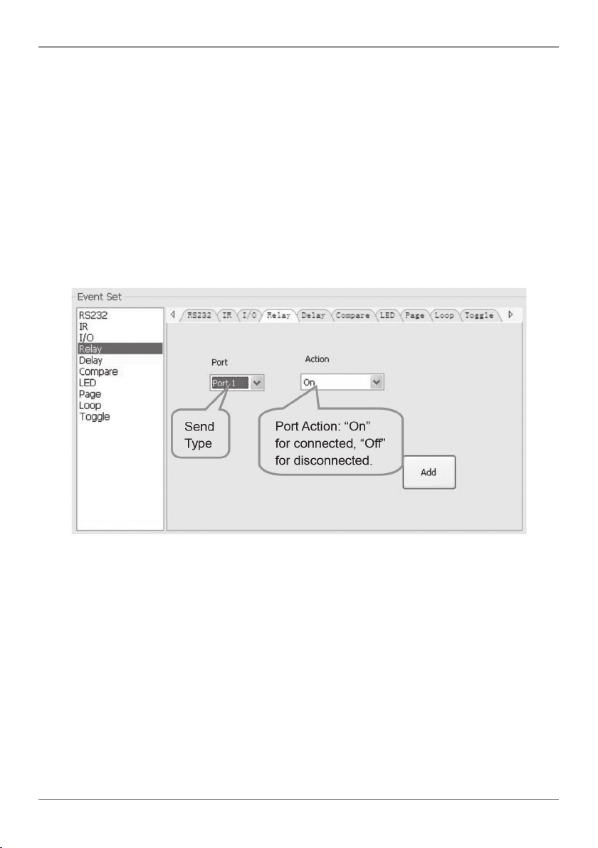
• Relay Setting
This item sets ports relay.
Figure 4-16. Repay Settings screen.
724-746-5500 | blackbox.com
Page 27
Page 28
Chapter 4: System Operation
• Delay setting
This item sets a delay time between two events; so when one event is finished, it will
delay for the set time, then start another event.
Figure 4-17. Delay setting screen.
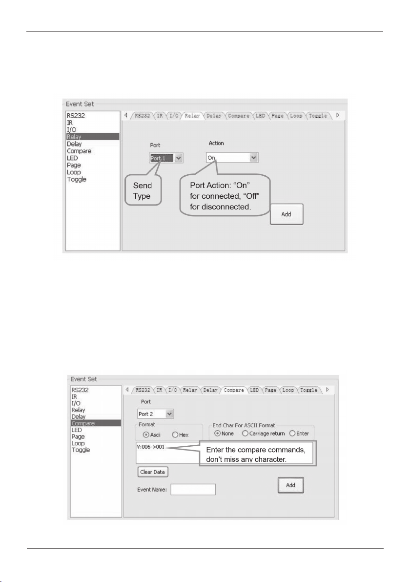
• Compare Setting
Use this item to compare RS-232 commands feedback. When the Wallplate Control
Panel sends an RS-232 command to the controlled device, the device will send feedback. If you add the correct feedback in the data, the Wallplate Control Panel will
compare it with the feedback received from the controlled device to verify whether or
not the command is working.
Figure 4-18. Compare Setting screen.
Page 28
724-746-5500 | blackbox.com
Page 29
Chapter 4: System Operation
1. The send port must be selected the same as the model setting; otherwise, the event
cannot be added. Port 1 cannot be used to compare, because there no receive pin
on this port.
2. You can set the event name, which is optional.
3. When you set the priority of events in one event list from top to bottom, you can
compare three or more events. When you send a serial command, you can compare
it to other events. If the compare is incorrect, the event behind compare will not be
executed.
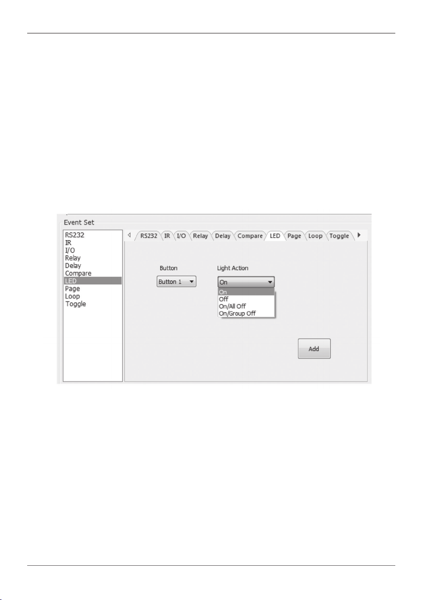
• LED setting
This item is used to set the Wallplate Control Panel’s button LEDs to turn on/off.
Figure 4-19. Event Set screen.
• Page setting
You can set the white buttons to “page” that includes four actions. To change different
actions, you will need the other white buttons to activate the page action number. See
the following example.
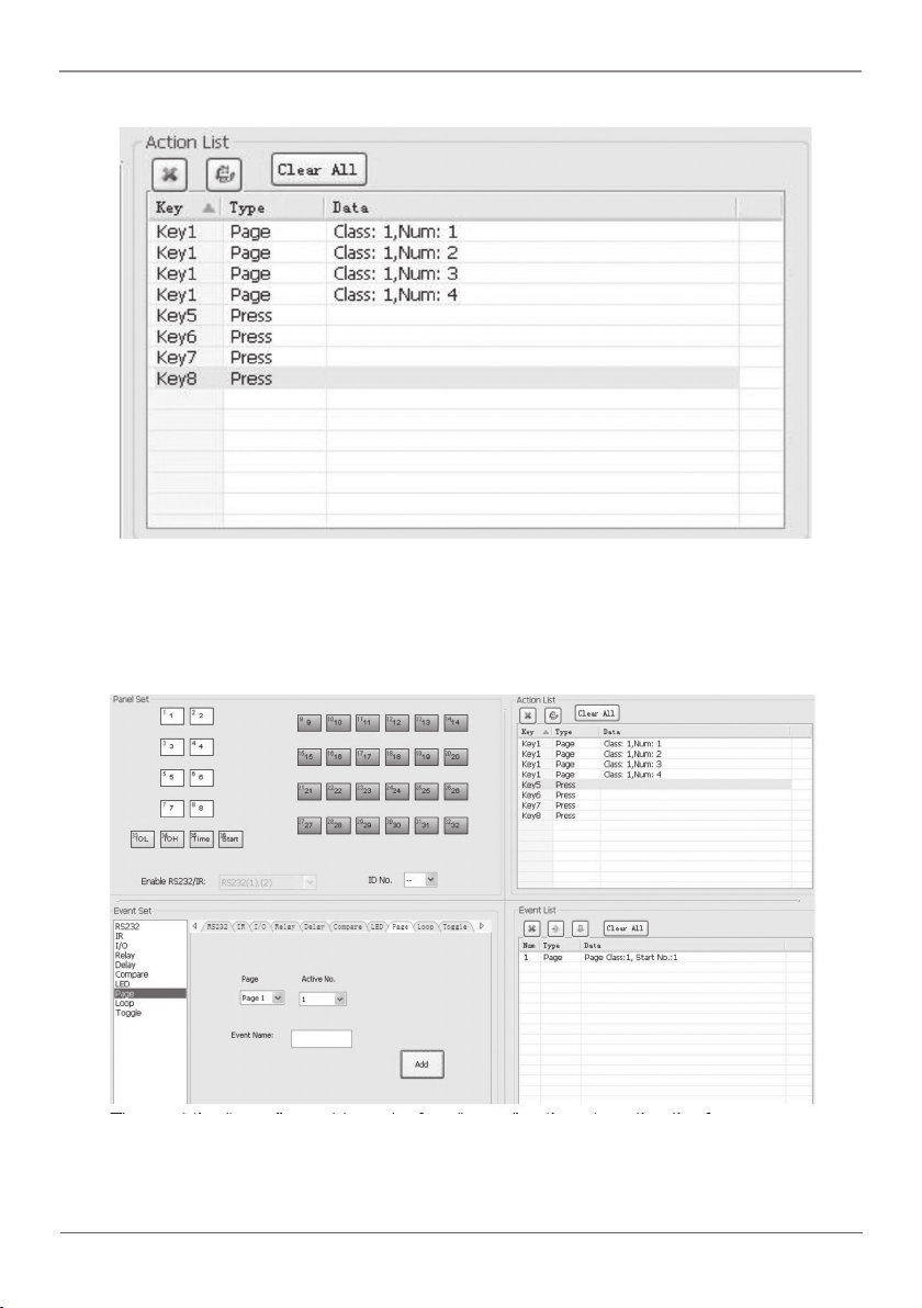
1. Take button1 for example: click key1 and select the action type “page,” then add the
four actions to the action list. Add the “press” action to add keys 5-8 to the list.
724-746-5500 | blackbox.com
Page 29
Page 30
Chapter 4: System Operation
Figure 4-20. Action List screen.
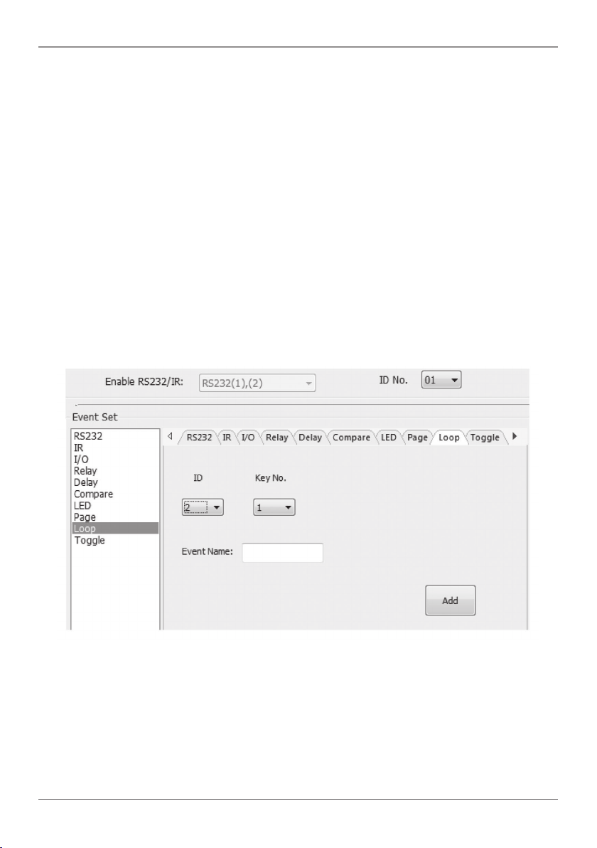
2. When setting events, you can add four different events to the four page actions of
key1, and the four other keys will be added to each page event.
Page 30
Figure 4-21. Adding page events.
724-746-5500 | blackbox.com
Page 31
Chapter 4: System Operation
Then set the “page” event to four “press” actions to activate the four page number:
key5-num1, key6-num2, key7-num3, and key8-num4.
a. When you press button5 and then button1, button1 will execute the event of num1,
if you press button1 more times, it will execute num1 more times;
b. When you press button6 and then button1, button1 will execute the event of num2,
if you press button1 more times, it will execute num2 more times;
c. When you press button7 and then button1, button1 will execute the event of num3,
if you press button1 more times, it will execute num3 more times;
d. When you press button8 and then button1, button1 will execute the event of num4,
if you press button1 more times, it will execute num4 more times.
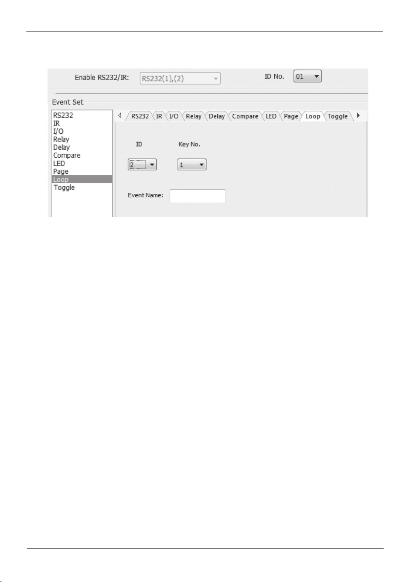
• Loop Setting
Use this item to loop Wallplate Control Panel. When using the loop function, you must
set the ID of each Wallplate Control Panel.
Figure 4-22. Loop setting screen.
724-746-5500 | blackbox.com
Page 31
Page 32
Chapter 4: System Operation
• Toggle Setting
Figure 4-23. Toggle setting screen.
Setting toggle is similar to the page setting. Toggle performs differently; its actions
include loop running. Toggle will perform as described next.
a. When you press button5 and then button1, button1 will execute the num1 event;
press button1 more times and it will execute num2, then num3->num4->num1 and
so on.
b. When you press button6 and then button1, button1 will execute the num2 event;
press button1 more times and it will execute num3, then num4->num1->num2 and
so on.
c. When you press button7 and then button1, button1 will execute the num3 event;
press button1 more times and it will execute num4, then num1->num2->num3 and
so on.
d. When you press button8 and then button1, button1 will execute the event of num4;
press button1 more times and it will
execute num1, then num2->num3->num4 and so on.
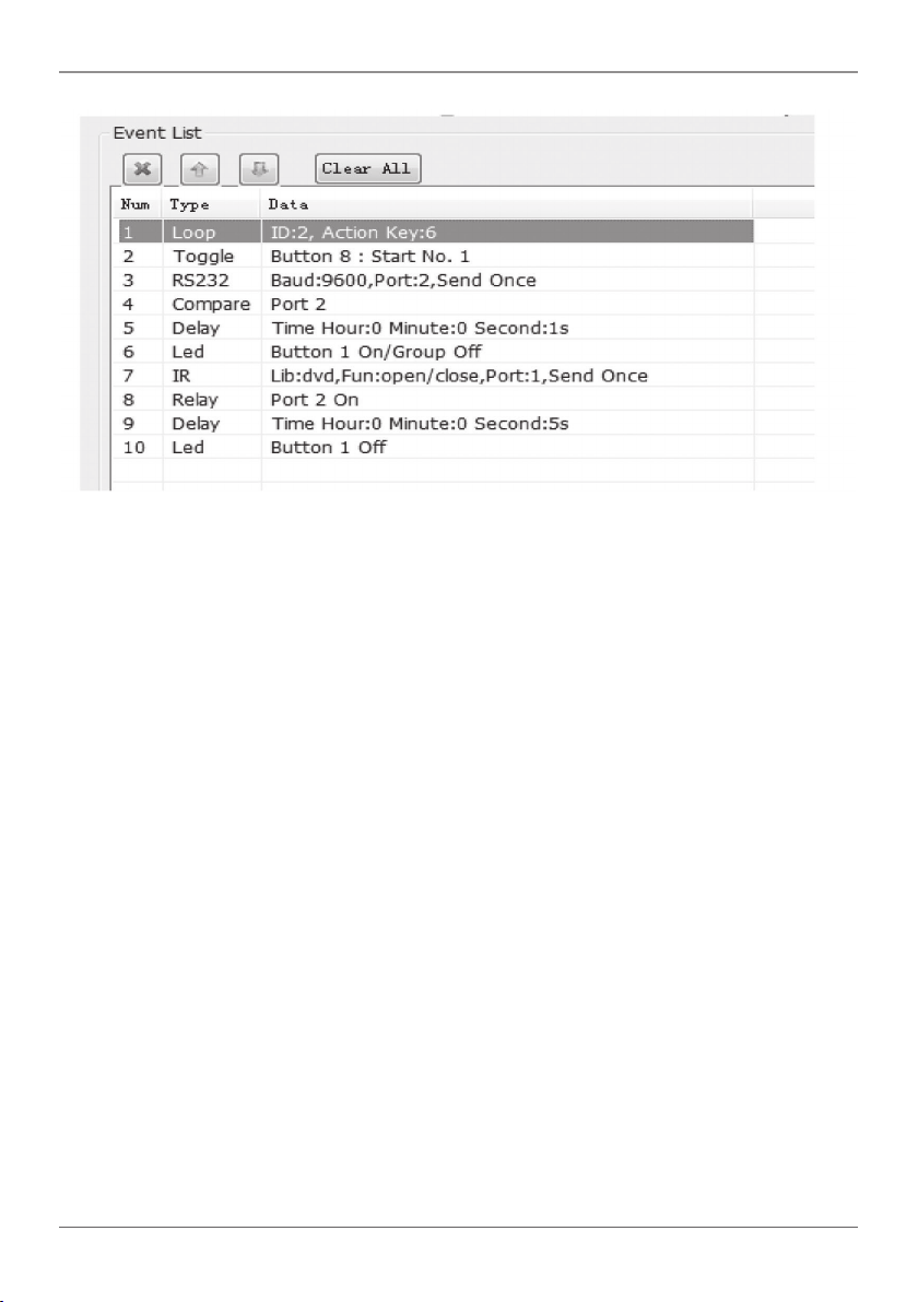
4.2.5 Event List
The event list shows all events of the selected action, and for each action of Wallplate
Control Panel, the most events that can be added is ten. The executing priority is from
1 to 10. If an event executes incorrectly, all the events behind it will not be executed.
Page 32
724-746-5500 | blackbox.com
Page 33
Chapter 4: System Operation
Figure 4-24. Event List screen.
4.3 Front Panel Operation
The front panel has crystal and luminescent programmable buttons: You can program
every button using the Black Box Control software. Connect the PC via USB or RS-232.
You can change every label inside the button. Choose the label you need and change it
as described below.
NOTE: A transparent paper table is included in the box with your product.
724-746-5500 | blackbox.com
Page 33
Page 34

Chapter 5: Troubleshooting and Maintenance
5. Troubleshooting and Maintenance
1. If the device cannot work, check and make sure the power cord is connected. Be
sure the power connector is not mixed or connected improperly. Then restart, and if
device still does not work, the Wallplate Control Panel might be broken. Contact
Black Box Technical Support at 724-746-5500 or [email protected] for instructions
for sending the unit back for repair.
2. When USB cannot open or is without a response, make sure the USB driver is
installed correctly, and then reconnect the USB cable.
3. When uploading the software and USB cannot be found, restart the software or
Wallplate Control Panel.
4. When the LED of a button is not lit, check if there is a compare configured for this
button. If yes, delete the compare and try again. If the device still does not work, the
LED may be broken. Contact Black Box Technical Support for instructions for sending
the unit back for repair.
5. When serial commands are sent without executing a function, check the baud rate
and the serial connection and make sure they are correct.
6. If the loop function will not work, reboot the Wallplate Control Panel.
Page 34
724-746-5500 | blackbox.com
Page 35

NOTES
724-746-5500 | blackbox.com
Page 35
Page 36
Black Box Tech Support: FREE! Live. 24/7.
Tech support the
way it should be.
Great tech support is just 60 seconds away at
724-746-5500 or blackbox.com.
About Black Box
Black Box provides an extensive range of networking and infrastructure products. You’ll find
everything from cabinets and racks and power and surge protection
products to media converters and Ethernet switches all supported by free, live 24/7
Tech support available in 60 seconds or less.
© Copyright 2015. Black Box Corporation. All rights reserved. Black Box® and the Double Diamond logo
are registered trademarks of BB Technologies, Inc. Any third-part y trademarks appearing in this manual
are acknowledged to be the proper ty of their respective owners.
AVS-C TRL8 , versio n 1
724-746-5500 | blackbox.com
 Loading...