

Page 1
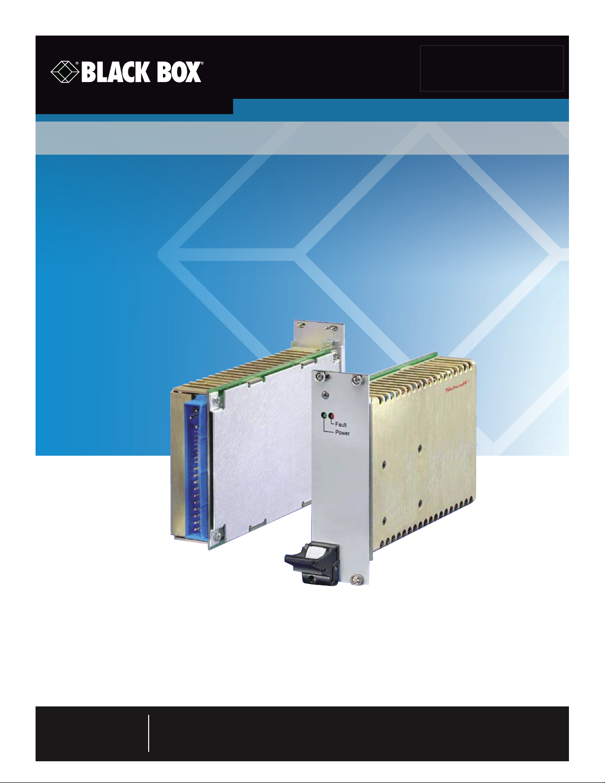
ACXMODH21-PS
Spare Optional Power Supply for the ACXMODH21R DKM Chassis
Complies with PICMIG Compact PCI specifications.
This highly efficient AC/DC converter with four output voltages was
designed specifically for use with the ACXMODH21R DKM Chassis.
Customer
Support
Information
Order toll-free in the U.S.: Call 877-877-BBOX (outside U.S. call 724-746-5500)
FREE technical support 24 hours a day, 7 days a week: Call 724-746-5500 or fax 724-746-0746
Mailing address: Black Box Corporation, 1000 Park Drive, Lawrence, PA 15055-1018
Web site: www.blackbox.com • E-mail: [email protected]
Page 2

Trademarks Used in this Manual
Trademarks Used in this Manual
Black Box and the Double Diamond logo are registered trademarks, and ServSwitch is a trademark, of BB Technologies, Inc.
Any other trademarks mentioned in this manual are acknowledged to be the property of the trademark owners.
Disclaimer
Black Box Network Services shall not be liable for damages of any kind, including, but not limited to, punitive, consequential
or cost of cover damages, resulting from any errors in the product information or specifications set forth in this document and
Black Box Network Services may revise this document at any time without notice.
CAUTION: Please read these operating instructions carefully before applying power. The warranty is subject to correct
input voltages being applied. Repairs or modifications made by anyone other than a qualified technician
will void the warranty.
We‘re here to help! If you have any questions about your application
Page 2
or our products, contact Black Box Tech Support at 724-746-550 0
or go to blackbox.com and click on “Talk to Black Box.”
You’ll be live with one of our technical experts in less than 60 seconds.
724-746-5500 | blackbox.com
Page 3

FCC and IC RFI Statements
Federal Communications Commission and Industry Canada Radio Frequency Interference
Statements
This equipment generates, uses, and can radiate radio-frequency energy, and if not installed and used properly, that is, in strict
accordance with the manufacturer’s instructions, may cause inter ference to radio communication. It has been tested and found to
comply with the limits for a Class A computing device in accordance with the specifications in Subpart B of Part 15 of FCC rules,
which are designed to provide reasonable protection against such interference when the equipment is operated in a commercial
environment. Operation of this equipment in a residential area is likely to cause interference, in which case the user at his own
expense will be required to take whatever measures may be necessary to correct the interference.
Changes or modifications not expressly approved by the party responsible for compliance could void the user’s authority to
operate the equipment.
This digital apparatus does not exceed the Class A limits for radio noise emis sion from digital apparatus set out in the Radio
Interference Regulation of Industry Canada.
Le présent appareil numérique n’émet pas de bruits radioélectriques dépassant les limites applicables aux appareils numériques
de la classe A prescrites dans le Règlement sur le brouillage radioélectrique publié par Industrie Canada.
724-746-5500 | blackbox.com
Page 3
Page 4

NOM Statement
Instrucciones de Seguridad
(Normas Oficiales Mexicanas Electrical Safety Statement)
1. Todas las instrucciones de seguridad y operación deberán ser leídas antes de que el aparato eléctrico sea operado.
2. Las instrucciones de seguridad y operación deberán ser guardadas para referencia futura.
3. Todas las advertencias en el aparato eléctrico y en sus instrucciones de operación deben ser respetadas.
4. Todas las instrucciones de operación y uso deben ser seguidas.
5. El aparato eléctrico no deberá ser usado cerca del agua—por ejemplo, cerca de la tina de baño, lavabo, sótano mojado o cerca
de una alberca, etc.
6. El aparato eléctrico debe ser usado únicamente con carritos o pedestales que sean recomendados por el fabricante.
7. El aparato eléctrico debe ser montado a la pared o al techo sólo como sea recomendado por el fabricante.
8. Servicio—El usuario no debe intentar dar servicio al equipo eléctrico más allá a lo descrito en las instrucciones de operación.
Todo otro servicio deberá ser referido a personal de servicio calificado.
9. El aparato eléctrico debe ser situado de tal manera que su posición no interfiera su uso. La colocación del aparato eléctrico
sobre una cama, sofá, alfombra o superficie similar puede bloquea la ventilación, no se debe colocar en libreros o gabinetes
que impidan el flujo de aire por los orificios de ventilación.
10. El equipo eléctrico deber ser situado fuera del alcance de fuentes de calor como radiadores, registros de calor, estufas u otros
aparatos (incluyendo amplificadores) que producen calor.
11. El aparato eléctrico deberá ser connectado a una fuente de poder sólo del tipo descrito en el instructivo de operación, o como
se indique en el aparato.
12. Precaución debe ser tomada de tal manera que la tierra fisica y la polarización del equipo no sea eliminada.
13. Los cables de la fuente de poder deben ser guiados de tal manera que no sean pisados ni pellizcados por objetos colocados
sobre o contra ellos, poniendo particular atención a los contactos y receptáculos donde salen del aparato.
14. El equipo eléctrico debe ser limpiado únicamente de acuerdo a las recomendaciones del fabricante.
15. En caso de existir, una antena externa deberá ser localizada lejos de las lineas de energia.
16. El cable de corriente deberá ser desconectado del cuando el equipo no sea usado por un largo periodo de tiempo.
17. Cuidado debe ser tomado de tal manera que objectos liquidos no sean derramados sobre la cubierta u orificios de ventilación.
18. Servicio por personal calificado deberá ser provisto cuando:
A: El cable de poder o el contacto ha sido dañado; u
B: Objectos han caído o líquido ha sido derramado dentro del aparato; o
C: El aparato ha sido expuesto a la lluvia; o
D: El aparato parece no operar normalmente o muestra un cambio en su desempeño; o
E: El aparato ha sido tirado o su cubierta ha sido dañada.
Page 4
724-746-5500 | blackbox.com
Page 5

Table of Contents
Table of Contents
1. Overview ...............................................................................................................................................................................6
1.1 Introduction ................................................................................................................................................................... 6
1.2 Features ......................................................................................................................................................................... 6
1.3 Components ..................................................................................................................................................................6
2. Specifications ......................................................................................................................................................................... 7
2.1 General Specifications ...................................................................................................................................................7
2.2 Detailed Specifications ................................................................................................................................................... 7
3. Caution and Notes .............................................................................................................................................................. 10
4. Installation ........................................................................................................................................................................... 11
724-746-5500 | blackbox.com
Page 5
Page 6

Chapter 1: Overview
CAUTION: Please read these operating instructions carefully before applying power. The warranty is subject to correct
input voltages being applied. Repairs or modifications made by anyone other than a qualified technician
will void the warranty.
1. Overview
1.1 Introduction
The ACXMODH21-PS is a highly efficient AC/DC converter with 4 output voltages, designed specifically for use with the
ACXMODH21R DKM Chassis.
The product is fully compliant with the PICMG Compact PCI specification and offers high currents on the 3.3 V and 5 V outputs.
1.2 Features
• Input voltage ranges from 90 to 264 VAC.
• Includes four high-current outputs.
• Fully compliant with PICMG Compact PCI specifications.
• High-density design in industry-standard 3 U x 8 HP x 160 mm cassette.
• Highly efficient topology with synchronous rectifiers.
• Remote sense, active current share for three outputs.
• Uses compact PCI compatible signaling.
• Included Or-ing FETs/Diode for true redundant operation.
1.3 Components
What’s Included
• (1) 5-VDC 30-amp internal power supply
System Components (sold separately)
• ACXMODH21R (21-Port Chassis)
Accessories
• Mating connector/intermediate plate 3 U (optional)
Page 6
724-746-5500 | blackbox.com
Page 7
2. Specifications
2.1 General Specifications
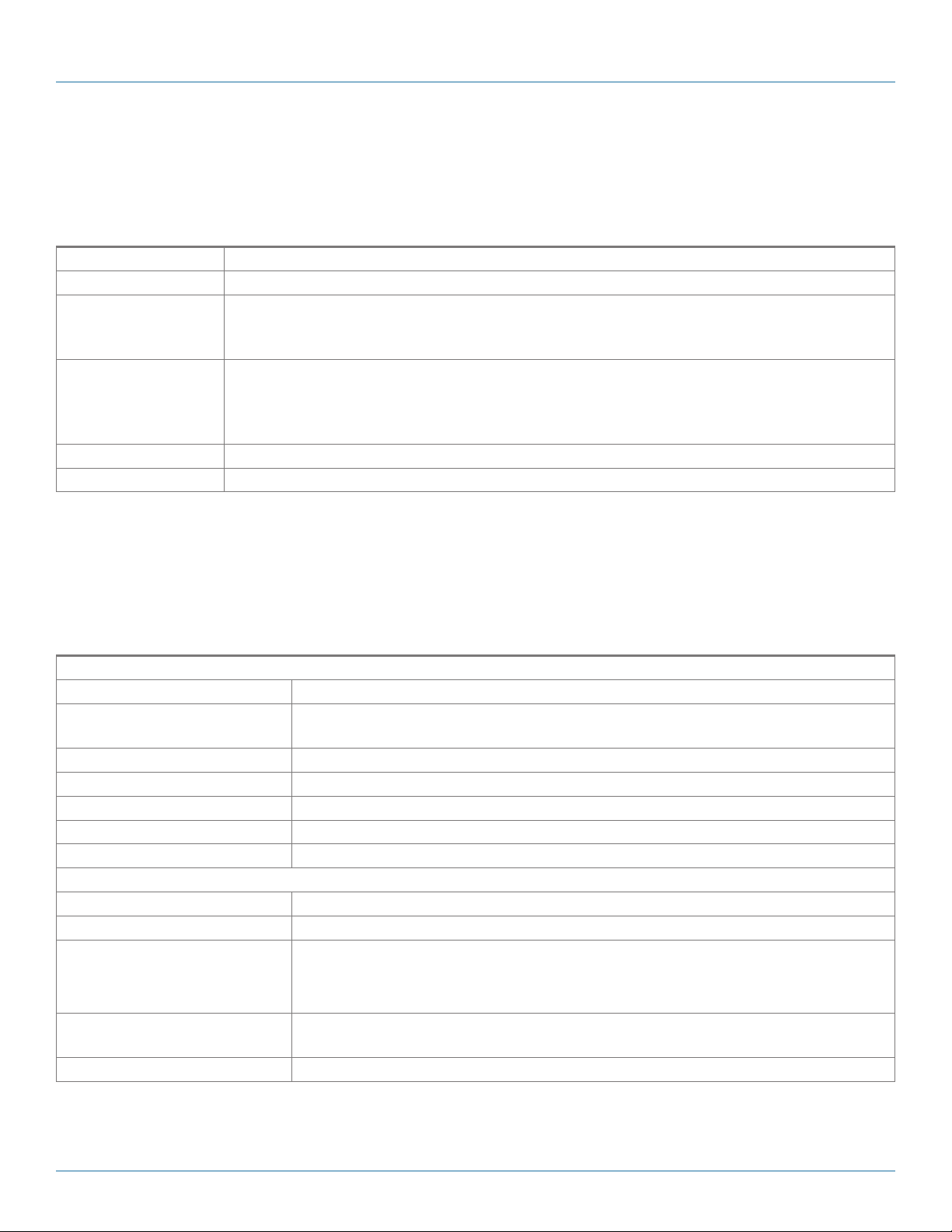
General Specifications
Approvals FCC, CE, UL, RoHS, WEEE
Number of Rack Units 3 U
Power Source: Internal power supply;
Input: 50/60 Hz, 3.5 A max., 250 Watts;
Output: 5 VDC, 25 A / 3.3 VDC, 20 A / 12 VDC, 4A
Selection Output 1: 5.0 VDC, 25 A;
Output 2: 3.3 VDC, 20 A;
Output 3: 12 VDC, 4 A;
Output 4: -12 VDC, 4 A
Dimensions 5"H x 4"W x 3"D (12.7 x 10.2 x 7.6 cm)
Weight 6 lb. (2.7 kg)
Chapter 2: Specifications
2.2 Detailed Specifications
Detailed Specifications
Input
Nominal input voltage (U
Input voltage with full output
power
Input frequency 47–63 Hz
Inrush current limitation 115/230 VAC <15/30 A
Input harmonics IEC/EN 61000-3-2 class A
Power factor U
Efficiency U
Output
Maximum output currents U
Output voltage setting accuracy U
Static line and load regulation U
Minimum load No minimum load requirements on V1, V2, V3
Hold-up time At full load, starting at Ui = 230 V AC > 20 ms
) 115 / 23 0 VAC
i nom
90 –264 VAC
i nom
i nom
...U
i min
i nom
...U
i min
for V1, V2, V3 (flat load characteristic) ±2%
for V4 (droop load characteristic) ±4%
For V4 Io3 > 0.75I
, I
> 0.95
o nom
, P
> 80%
o nom
(Vo1, Vo2, Vo3, Vo4) 40/40/5.5 /2 A
i max
, 50%
i max
, Tc = 25°C ±1% U
Io nom
, I
/ U
o nom
i nom
o4
, 5...100 % I
o nom
o max
724-746-5500 | blackbox.com
Page 7
Page 8

Chapter 2: Specifications
Detailed Specifications (continued)
Output (continued)
Dynamic load regulation
Start-up time U
Output voltage ripple and noise U
Protection
Input fuses Not user accessible (fuses in both lines) 4 AT
Input transient protection Varistor
Output no-load, short circuit proof, overload (self recovery) 105...130% I
Overvoltage protection Latch style 120… 130% U
Overload protection Self recovery 105…130% I
Overtemperature Automatic output power derating at Tc = 90°C
Control
Current share 3 sharing buses for V1, V2, V3; up to 6 units;
Remote sense Available on V1, V2, and V3
Enable Contact closure to GND extern to start up unit
Inhibit TTL compatible signal, inhibited at GND or TTL “0”
Power Fail (Fail#) Indicates pre-diode voltage of any outputs < 90% and/or an input voltage failure
Temperature warning (DEG#) Indicates temperature within 20°C of thermal power derating
Status indication LEDs: Input OK (green), Output failure (red)
Safety and EMC
Approvals EN 60950 (TÜV), UL 1950, cUL 1950
Protection degree IP 20
Electric strength test voltage Class I, I/case (basic insulation) 1.5 kV AC
Electric strength test voltage Class I, I/O (reinforced insulation) 3 kV AC
Electric strength test voltage Class I, O/case (functional insulation) 0.5 kV AC
Electrostatic discharge IEC/EN 61000-4-2, level 3 (contact/air) 4/8 kV, criterion B
Electromagnetic field IEC/EN 61000-4-3, level 3 10 V/m, criterion A
Electr. fast transients/burst IEC/EN 61000-4-4, level 3 (direct/capacitive) 1/2 kV, criterion B
Surge IEC/EN 61000-4-5, level 3 (L/L, L/C) 1/2 kV, criterion B
Conducted disturbances IEC/EN 61000-4-6, level 2 3V, criterion A
Electromagnetic emissions CISPR 22/EN 55022, conducted / radiated class A/A
V1: D I
=10 A, dIO/dt=2A/μs ± 5% U
0
V2: D I0=10 A, dIO/dt=2A/μs ± 5% U
V3: D I0=2 A, dIO/dt=2A/μs ± 5% U
V4: D I0=0.5 A, dIO/dt=2A/μs ± 5% U
, I
i nom
i nom
<500 ms
o nom
, I
, 20 MHz BW <1% or < 60 mV*
o nom
*whichever is greater
o nom
o nom
Droop load characteristic for V4
(Ui < 90 VAC)
0 nom
0 nom
0 nom
, 1 ms
, 1 ms
, 1 ms
0 nom
, 1 ms
0 nom
Page 8
724-746-5500 | blackbox.com
Page 9
Chapter 2: Specifications
Detailed Specifications (continued)
Environmental Specifications
Operating temperature U
Storage temperature Non-operational -40...85 °C
Relative humidity Non-condensing 5…95%
Shock IEC/EN 60068-2-27, 11 ms max. 20 gn
Random vibration IEC/EN 60068-2-64, 10...2000/200...2000 6 Grms
MTBF MIL-HDBK-217F Notice 2, GB, 40°C 279.000 h
Mechanical Data
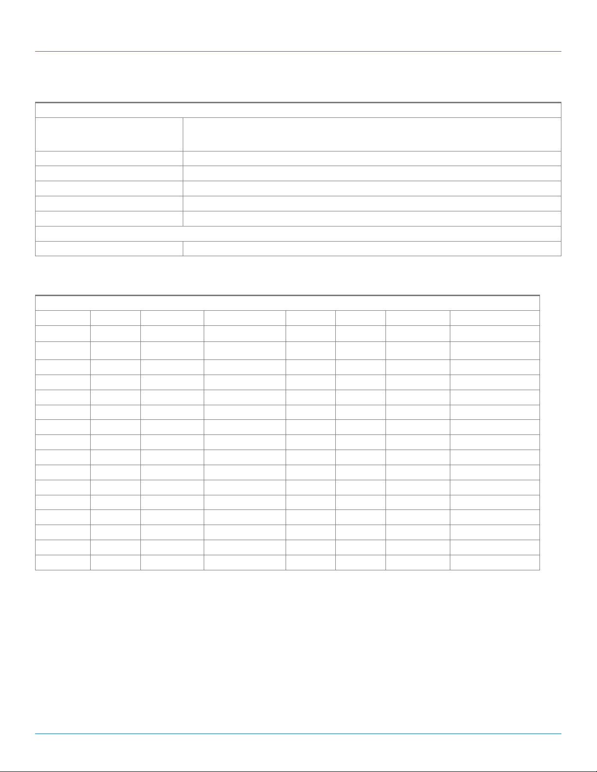
Mechanical data (H, W, D) 3 U, 8 HP, 160 mm
Pin allocation
Connector: Positronic (PCIH47M400A1)
1 2
Pin
Signal Name Description Pin
1–4 M V1 V1 Output 32 M nc Not connected
5–12 M RTN V1 and V2 Return 33 M V2SENSE V2 Remote Sense
, I
i nom
, cooling by forced air flow with 400 LFM 0...50 °C
o nom
derating from 50 to 70 °C of 2.5% per °C
1 2
Signal Name Description
13–18 M V2 V2 Output 34 M S RTN Sense Return
19 M RTN V3 Return 35 M V1SHARE V1 Current Share
20 M V3 V3 Output 36 M V3SENSE V3 Remote Sense
21 M V4 V4 Output 37 M Reserved
3
22 M RTN Signal Return 38 M DEG# Degrade Signal
23 M Reserved Reserved 39 M INH# Inhibit
24 M RTN V4 Return 40 M Reserved
25 M Reserved
3
41 M V2SHARE V2 Current Share
3
26 M Reserved Reserved 42 M FAL# Fail Signal
27 S EN# Enable 43 M Reserved
28 M Reserved
3
44 M V3SHARE V3 Current Share
3
29 M NC Not connected 45 L CGND Chassis Ground
30 M V1SENSE V1 Remote Sense 46 M ACN AC Input Neutral
31 M Reserved
1
Pin number illustrated are of the female backplane connector
2
L=first mate, M=second mate, S=last mate
3
For future options
3
47 M ACL AC Input Line
724-746-5500 | blackbox.com
Page 9
Page 10

Chapter 3: Caution and Notes
3. Caution and Notes
CAUTION:
These component-level power supplies are intended exclusively for installation within other equipment by an
industrial assembly operation or by professional installers. These are Class I power supplies; the ground pin of input
connector J1 must be properly connected to earth ground in end use. Component power supplies are to be installed
in end-use equipment according to the requirements of the safety standard used for that equipment. These power
supplies are not designed to be operated outside of an enclosure which provides a means of mechanical, electrical,
and fire protection. To maintain SELV requirements, the outputs should not be connected together in any manner
which causes the total output voltage to exceed 60 VDC.
PROTECTIVE EARTHING:
The Power Supply must be properly grounded to mains protective earthing termination at end use.
FUSING:
In case of failure, the Power Supply must be returned to Black Box. There are no user-serviceable parts in the Power
Supply.
LIMITED WARRANTY:
Black Box warrants each power supply of its manufacture for a period of two (2) years from the date of original shipment. This warranty applies to defects in materials and workmanship that result in nonperformance to published
specifications.
Black Box assumes no liabilities for consequential damages of any kind through the use or misuse of its products by
any user. No other obligations are expressed or implied. Please note that the specifications, terms, and conditions
stated are subject to change without notice.
Page 10
724-746-5500 | blackbox.com
Page 11
Chapter 4: Installation
4. Installation
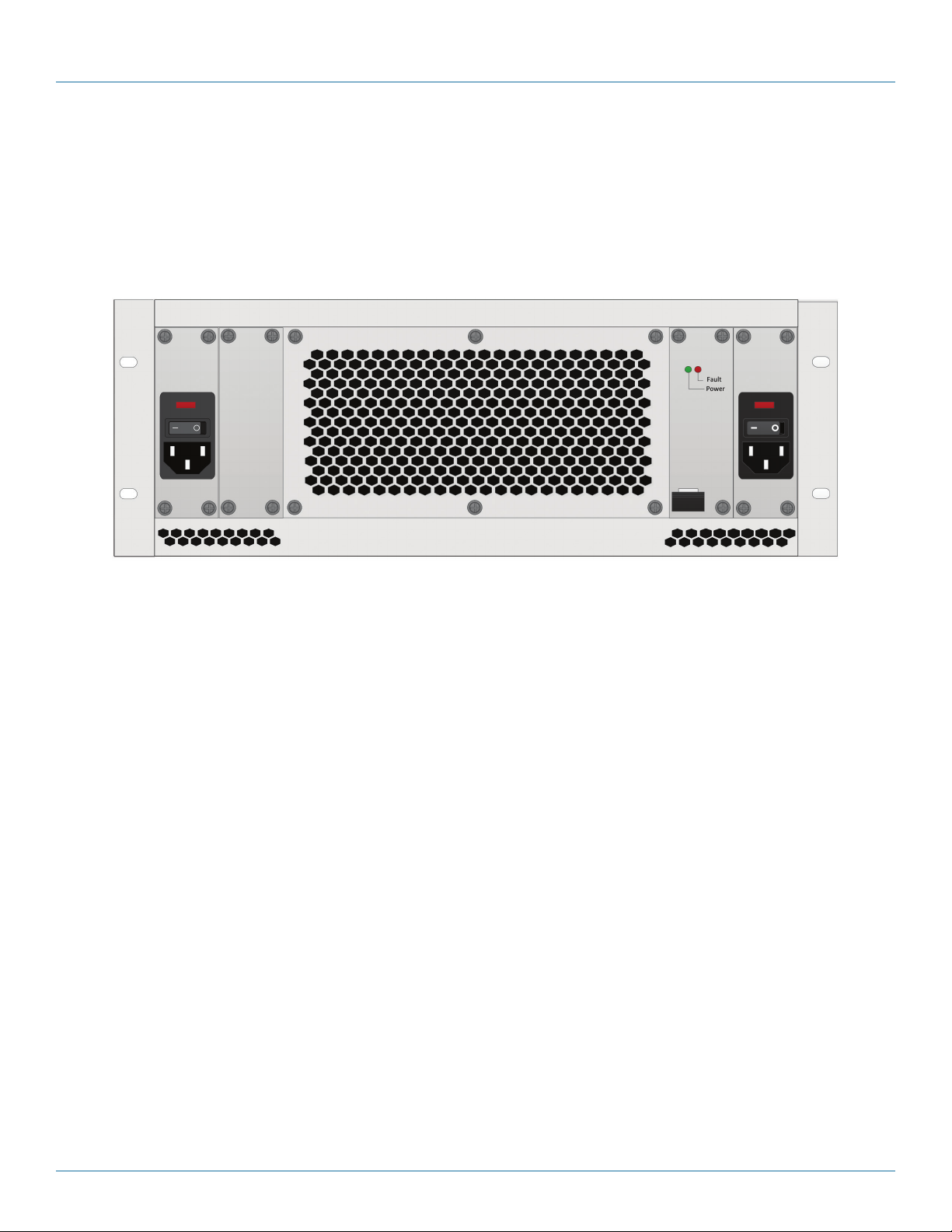
You can install the ACXMODH21-PS in the available slot. You will need to remove the screws to remove the blanking plate, then
install the ACXMODH21-PS into the slot and push in firmly to establish a good connection. Once installed, secure the power
supply with screws and latch. Once installed and secured, you can use the secondary/redundant power input.
724-746-5500 | blackbox.com
Pa g e 11
Page 12

Black Box Tech Support: FREE! Live. 24/7.
Tech support the
way it should be.
Great tech support is just 60 seconds away at 724-746-5500 or blackbox.com.
About Black Box
Black Box provides an extensive range of networking and infrastructure products. You’ll find everything from cabinets and racks
and power and surge protection products to media converters and Ethernet switches all supported by free, live 24/7 Tech support
available in 60 seconds or less.
© Copyright 2014. Black Box Corporation. All rights reserved. Black Box® and the Double Diamond logo are registered trademarks of BB Technologies, Inc.
Any third-party trademarks appearing in this manual are acknowledged to be the property of their respective owners.
ACXMODH21-PS, versio n 1
724-746-5500 | blackbox.com
 Loading...