

Page 1

Application Programming Interface (API) Manual
DKM FX and DKM FX Compact
Order toll-free in the U.S.: Call 877-877-BBOX (outside U.S. call 724-746-5500)
FREE technical support 24 hours a day, 7 days a week: Call 724-746-5500 or fax
724-746-0746 • Mailing address: Black Box Corporation, 1000 Park Drive, Lawrence,
PA 15055-1018 • Web site: www.blackbox.com • E-mail: info @blackbox.com
Customer
Support
Information
ACX048 ACXC8 ACXC64
ACX080 ACXC16 ACXC80
ACX160 ACXC32 ACXC48F16
ACX288 ACXC48 ACXC48F32
Page 2

Page 2
724-746-5500 | blackbox.com
ACX048 API manual
Trademarks Used in this Manual
Trademarks Used in this Manual
Black Box and the Double Diamond logo are registered trademarks of BB
Technologies, Inc.
TOSLINK is a registered trademark of Kabushiki Kaisha Toshiba dba Toshiba
Corporation.
Any other trademarks mentioned in this manual are acknowledged to be
the property of the trademark owners.
Page 3

Page 3
724-746-5500 | blackbox.com
ACX048 API manual
FCC and IC RFI Statements and NOM Statement
FEDERAL COMMUNICATIONS COMMISSION AND
INDUSTRY CANADA RADIO FREQUENCY INTERFERENCE STATEMENTS
This equipment generates, uses, and can radiate radio-frequency energy,
and if not installed and used properly, that is, in strict accordance with the
manufacturer’s instructions, may cause inter ference to radio communication.
It has been tested and found to comply with the limits for a Class A computing
device in accordance with the specifications in Subpart B of Part 15 of FCC rules,
which are designed to provide reasonable protection against such interference
when the equipment is operated in a commercial environment. Operation of
this equipment in a residential area is likely to cause interference, in which case
the user at his own expense will be required to take whatever measures may be
necessary to correct the interference.
Changes or modifications not expressly approved by the party responsible
for compliance could void the user’s authority to operate the equipment.
This digital apparatus does not exceed the Class A limits for radio noise
emis sion from digital apparatus set out in the Radio Interference Regulation
of Industry Canada.
Le présent appareil numérique n’émet pas de bruits radioélectriques dépassant les
limites applicables aux appareils numériques de la classe A prescrites dans le
Règlement sur le brouillage radioélectrique publié par Industrie Canada.
Normas Oficiales Mexicanas (NOM)
Electrical Safety Statement
INSTRUCCIONES DE SEGURIDAD
1. Todas las instrucciones de seguridad y operación deberán ser leídas antes
de que el aparato eléctrico sea operado.
2. Las instrucciones de seguridad y operación deberán ser guardadas para
referencia futura.
3. Todas las advertencias en el aparato eléctrico y en sus instrucciones de
operación deben ser respetadas.
4. Todas las instrucciones de operación y uso deben ser seguidas.
Page 4

Page 4
724-746-5500 | blackbox.com
ACX048 API manual
NOM Statement
4. Todas las instrucciones de operación y uso deben ser seguidas.
5. El aparato eléctrico no deberá ser usado cerca del agua—por ejemplo,
cerca de la tina de baño, lavabo, sótano mojado o cerca de una alberca,
etc.
6. El aparato eléctrico debe ser usado únicamente con carritos o pedestales
que sean recomendados por el fabricante.
7. El aparato eléctrico debe ser montado a la pared o al techo sólo como sea
recomendado por el fabricante.
8. Servicio—El usuario no debe intentar dar servicio al equipo eléctrico más allá
lo descrito en las instrucciones de operación. Todo otro servicio deberá ser
referido a personal de servicio calificado.
9. El aparato eléctrico debe ser situado de tal manera que su posición no
interfiera su uso. La colocación del aparato eléctrico sobre una cama, sofá,
alfombra o superficie similar puede bloquea la ventilación, no se debe
colocar en libreros o gabinetes que impidan el flujo de aire por los orificios
de ventilación.
10. El equipo eléctrico deber ser situado fuera del alcance de fuentes de calor
como radiadores, registros de calor, estufas u otros aparatos (incluyendo
amplificadores) que producen calor.
11. El aparato eléctrico deberá ser connectado a una fuente de poder sólo del
tipo descrito en el instructivo de operación, o como se indique en el
aparato.
12. Precaución debe ser tomada de tal manera que la tierra fisica y la
polarización del equipo no sea eliminada.
13. Los cables de la fuente de poder deben ser guiados de tal manera que no
sean pisados ni pellizcados por objetos colocados sobre o contra ellos,
poniendo particular atención a los contactos y receptáculos donde salen
del aparato.
14. El equipo eléctrico debe ser limpiado únicamente de acuerdo a las
recomendaciones del fabricante.
15. En caso de existir, una antena externa deberá ser localizada lejos de las
lineas de energia.
Page 5

Page 5
724-746-5500 | blackbox.com
ACX048 API manual
NOM Statement
16. El cable de corriente deberá ser desconectado del cuando el equipo no sea
usado por un largo periodo de tiempo.
17. Cuidado debe ser tomado de tal manera que objectos liquidos no sean
derramados sobre la cubierta u orificios de ventilación.
18. Servicio por personal calificado deberá ser provisto cuando:
A: El cable de poder o el contacto ha sido dañado; u
B: Objectos han caído o líquido ha sido derramado dentro del aparato; o
C: El aparato ha sido expuesto a la lluvia; o
D: El aparato parece no operar normalmente o muestra un cambio en su
desempeño; o
E: El aparato ha sido tirado o su cubierta ha sido dañada.
Page 6

Page 6
724-746-5500 | blackbox.com
ACX048 API manual
Table of Contents
Table of Contents
1. About this Manual .....................................................................................9
1.1 S cope .................................................................................................9
1.2 Validity ...............................................................................................9
1.3 Cautions and Notes ...........................................................................9
2. Safety Instructions ...................................................................................10
3. Overview .................................................................................................11
3.1 Description .......................................................................................11
3.2 Access Options ................................................................................11
3.3 System Overview .............................................................................11
3.4 Product Range .................................................................................12
3.5 Device Views ...................................................................................13
3.5.1 DKM FX 288-Port ..................................................................13
3.5.2 DKM FX 160-Port ..................................................................14
3.5.3 DKM FX 80-Port ....................................................................15
3.5.4 DKM FX 48-Port ....................................................................15
3.5.5 DKM FX Compact 48-Port ....................................................16
3.5.6 DKM FX Compact 32-Port .....................................................16
3.5.7 DKM FX Compact 16-Port .....................................................17
3.6 Status LEDs ........................................................................................18
4. Installation ...............................................................................................20
4.1 What’s Included ...............................................................................20
4.2 System Setup ...................................................................................20
5. Configuration ..........................................................................................21
5.1 General Remarks .............................................................................21
5.2 DKM FX or DKM FX Compact Configuration ..................................21
5.2.1 System Data ...........................................................................21
5.2.2 Network.................................................................................23
5.3 Communication Setup .....................................................................26
5.4 Telegram Structure ...........................................................................27
5.4.1 Request ..................................................................................27
5.4.2 Response ...............................................................................27
5.5 Constraints.......................................................................................27
Page 7

Page 7
724-746-5500 | blackbox.com
ACX048 API manual
Table of Contents
6. Operation ............................................................................................28
6.1 System Requests ..............................................................................28
6.2 Switch Commands ...........................................................................29
6.2.1 Switch Off All Ports .............................................................29
6.2.2 Get CPU Device Connected to CON Device.........................29
6.2.3 Set CPU Device Connection to CON Device ........................30
6.2.4 Get CPU Devices Connected to CON Devices ......................30
6.2.5 Set Connections of CPU Devices to CON Devices ................31
6.2.6 Get CON Device Connected to CPU Device.........................32
6.2.7 Set CON Device Connection to CPU Device ........................33
6.2.8 Get CON Devices Connected to CPU Devices ......................33
6.2.9 Set Connection of CON Devices to CPU Devices .................34
6.2.10 Set CON Device Connection to CPU Device
(Single Bidirectional Connection—KVM Full Access) ...........35
6.2.11 Set Connection of CON Devices to CPU Devices
(Multiple Bidirectional Connections—Full Access) ...............36
6.2.12 Get All Connections ............................................................36
6.2.13 Set Connection for All CON Devices and CPU Devices ........38
6.2.14 Set Extended Connection ....................................................39
6.3 Assignments ....................................................................................39
6.3.1 Get Virtual CON Device .......................................................39
6.3.2 Set Virtual CON Device to a Real CON Device .................... 40
6.3.3 Get Real CPU Device ...........................................................41
6.3.4 Set Real CPU Devices to a Virtual CPU Device .....................41
6.3.5 Get Virtual CON Devices .....................................................42
6.3.6 Set Virtual CON Devices to Real CON Devices .....................43
6.3.7 Get Real CPU Devices ..........................................................43
6.3.8 Set Real CPU Devices .......................................................... 44
6.4 Best Practice ....................................................................................45
6.4.1 Full Access (Establishing a KVM Connection) ......................45
6.4.2 Video Access (Establishing a Video-Only Connection) .........45
6.4.3 Private Access (Establishing an Exclusive KVM Session) ...... 46
6.4.4 USB 2.0 Access (Establishing a USB 2.0 Data Connection) . 46
7. Specifications ...........................................................................................47
7.1 System Requests ............................................................................. 48
7.2 Switch Commands ...........................................................................49
7.2.1 Switch Off All Ports .............................................................49
7.2.2 Get CPU Device Connected to CON Device.........................50
7.2.3 Set CPU Device Connection to CON Device ........................51
Page 8

Page 8
724-746-5500 | blackbox.com
ACX048 API manual
Table of Contents
7.2.4 Get CPU Devices Connected to CON Devices ......................52
7.2.5 Set Connections of CPU Devices to CON Devices ................54
7.2.6 Get CON Device Connected to CPU Device.........................55
7.2.7 Set CON Device Connection to CPU Device ........................56
7.2.8 Get CON Devices Connected to CPU Devices ......................57
7.2.9 Set Connection of CON Devices to CPU Devices .................58
7.2.10 Set CON Device Connection to CPU Device (Bidirectional) . . 59
7.2.11 Set Connection of CON Devices to CPU Devices
(Bidirectional) .......................................................................60
7.2.12 Get All Connections ............................................................61
7.2.13 Set Connection for All CON Devices and CPU Devices ........63
7.2.14 Set Extended Connection ....................................................65
7.3 Assignments ....................................................................................66
7.3.1 Get Virtual CON Device .......................................................66
7.3.2 Set Virtual CON Device to a Real CON Device .....................67
7.3.3 Get Real CPU Device ...........................................................68
7.3.4 Set Real CPU to a Virtual CPU .............................................69
7.3.5 Get Virtual CON Devices .....................................................70
7.3.6 Set Virtual CON Devices to Real CON Devices .....................72
7.3.7 Get Real CPU Device ...........................................................73
7.3.8 Set Real CPU Devices ...........................................................75
7.4 Connector Pinouts ...........................................................................76
8. Troubleshooting .......................................................................................77
8.1 Network Error ..................................................................................77
8.2 Failure at the Matrix .........................................................................77
9. Technical Support ....................................................................................78
10. Glossary .......................................................................................79
Page 9

Page 9
724-746-5500 | blackbox.com
ACX048 API manual
Chapter 1: About this Manual
1. About This Manual
1.1 Scope
This manual describes how to install your DKM FX API, how to operate it, and
how to perform troubleshooting.
1.2 Validity
This manual is valid for all devices listed on the front page. The product code is
printed on the base of the devices.
1.3 Cautions and Notes
The following conventions are used in this manual:
WARNING or CAUTION: This indicates an important operating instruction that
should be followed to avoid any potential damage to hardware or property, loss
of data, or personal injury.
NOTE: This indicates important information to help you make the best use of this
product.
Page 10

Page 10
724-746-5500 | blackbox.com
ACX048 API manual
Chapter 2: Safety Instructions
2. Safety Instructions
For reliable and safe long-term operation of your DKM FX, follow these guidelines:
Installation
• Only use in dry, indoor environments.
• The DKM FX and the power supply units can get warm. Don’t put them in an
enclosed space without any airflow.
• Do not obscure ventilation holes.
• Only use power supplies originally supplied with the product or
manufacturer-approved replacements. Do not use a power supply if it appears to
be defective or has a damaged case.
• Connect all power supplies to grounded outlets. In each case, make sure that the
ground connection is maintained from the outlet socket to the power supply’s AC
power input.
• Do not connect the link interface to any other equipment, particularly network or
telecommunications equipment.
• Only connect devices to the serial interface that are sufficiently secured against
short circuits and false voltages at the serial interface.
• To disconnect the switch from the power supply, remove the power cord cables
of all power supply units that are in use or set the power switch (if available)
to the OFF position.
• Take any required ESD precautions.
Repair
• Do not attempt to open or repair a power supply unit.
• Do not attempt to open or repair the DKM FX or DKM Compact. There are no
user-serviceable parts inside.
• Contact Black Box Technical Support at 724-746-5500 or info@blackbox.com
if there is a fault.
Page 11

Page 11
724-746-5500 | blackbox.com
ACX048 API manual
Chapter 3: Overview
3. Overview
3.1 Description
The DKM FX API is used to control the matrix externally by serial commands via
serial (RS-232) or network (TCP/IP) connection.
The DKM FX API provides the full scope of switching functionality. It does not
support the configuration of a DKM FX system.
3.2 Access Options
You have the following options to access the DKM FX for
external serial control:
Table 3-1. Access options.
Access option Symbol
Serial interface
TCP/ IP Interface
NOTE: Both serial interface and TCP/IP interface use the same commands for the
operation of the DKM FX matrix.
3.3 System Overview
A DKM FX matrix can be connected to an external serial control via the CPU
board and its connectors.
The CPU board provides the possibility for both serial and TCP/IP connections.
The serial connection to an external serial control is established by using a serial
cable with DB9 connectors or a DB9-to-RJ-45 adapter cable (DKM FX Compact).
The TCP/IP connection is established by using a CATx network cable.
Page 12

Page 12
724-746-5500 | blackbox.com
ACX048 API manual
Chapter 3: Overview
Figure 3-1 shows the system overview. Table 3-2 describes its components.
Figure 3-1. System overview (exemplary).
Table 3-2. System components.
Number Component
1 DKM FX matrix
2 Serial connection cable (DB9 or DB9-to-RJ- 45 adapter cable)
3 External serial control (RS-232, Option 1)
4 Network connection cable (CATx)
5 External serial control (TCP/ IP, Option 2)
3.4 Product Range
Table 3-3. Available products.
Number Description
DKM FX and DKM FXC-API
ACX-API DKM FX matrix application programming interface (API )
Page 13

Page 13
724-746-5500 | blackbox.com
ACX048 API manual
Chapter 3: Overview
3.5 Device Views
In Sections 3.5.1 through 3.5.7, Figures 3-2 through 3-8 illustrate the DKM FX and
DKM FX Compact chassis serial and TCP/IP connectors. Tables 3-4 through 3-10
describe these components.
3.5.1 DKM FX 288-Port
2
1
Figure 3-2. Front view, ACX288.
Table 3-4. ACX288 components.
Number Component
1 Serial connector (DB9)
2 TCP/IP connector (RJ-45)
Page 14

Page 14
724-746-5500 | blackbox.com
ACX048 API manual
Chapter 3: Overview
3.5.2 DKM FX 160-Port
2
1
Figure 3-3. Front view, ACX160.
Table 3-5. ACX160 components.
Number Component
1 Serial connector (DB9)
2 TCP/IP connector (RJ-45)
Page 15

Page 15
724-746-5500 | blackbox.com
ACX048 API manual
Chapter 3: Overview
3.5.3 DKM FX 80-Port
1 2
Figure 3-4. Front view, ACX080.
Table 3-6. ACX080 components.
Number Component
1 Serial connector (DB9)
2 TCP/IP connector (RJ-45)
3.5.4 DKM FX 48-Port
1 2
Figure 3-5. Front view, ACX048.
Table 3-7. ACX048 components.
Number Component
1 Serial connector (DB9)
2 TCP/IP connector (RJ-45)
Page 16

Page 16
724-746-5500 | blackbox.com
ACX048 API manual
Chapter 3: Overview
3.5.5 DKM FX Compact 48-Port
1 2
Figure 3-6. Front view, ACXC48.
Table 3-8. ACXC48 components.
Number Component
1 Serial connector (RJ-45)
2 TCP/IP connector (RJ-45)
3.5.6 DKM FX Compact 32-Port
1 2
Figure 3-7. Front view, ACXC32.
Table 3-9. ACXC32 components.
Number Component
1 Serial connector (RJ-45)
2 TCP/IP connector (RJ-45)
Page 17

Page 17
724-746-5500 | blackbox.com
ACX048 API manual
Chapter 3: Overview
3.5.7 DKM FX Compact 16-Port
1 2
Figure 3-8. Front view, ACXC16.
Table 3-10. ACXC16 components.
Number Component
1 Serial connector (RJ-45)
2 TCP/IP connector (RJ-45)
Page 18

Page 18
724-746-5500 | blackbox.com
ACX048 API manual
Chapter 3: Overview
3.6 Status LEDs
The DKM FX and DKM FX Compact Status LED indicators are shown in Figure 3-9
and described in Table 3-11.
Figure 3-9. CPU board, front view.
Page 19

Page 19
724-746-5500 | blackbox.com
ACX048 API manual
Chapter 3: Overview
Table 3-11. Status LEDs on the CPU board.
Number LED Status Description
1 Status 1
White CPU board is in registration process
Blue flashing Registration at the matrix is started
Red flashing Registration is in progess
Green flashing Operating condition
Green CPU board de-registered
2
TCP/IP
Status 1
Red Operating condition
Off No connection
3
TCP/IP
Status 2
Green flashing Active data traffic
Off No active data traffic
4 Status 2
White CPU board is in registration process
Red flashing Registration at the matrix is started
Off Operating condition
NOTE: Because of variations in the LED type, “white” may also appear as light
purple or light blue.
Page 20

Page 20
724-746-5500 | blackbox.com
ACX048 API manual
Chapter 4: Installation
4. Installation
4.1 What’s Included
Your package contains the following items. If anything is missing or damaged,
contact Black Box Technical Support at 724-746-5500 or info@blackbox.com.
4.2 System Setup
NOTE: If you are a first-time user, we recommend that you set up the system
in the same room as a test setup. This will allow you to identify and solve
any cabling problems, and experiment with your system more conveniently.
Setup of the external control
1. Install the CPU and I/O boards.
2. Connect the keyboard, mouse, and monitor to the CPU board of the DKM FX.
3. Connect the matrix to the power supply.
4. Open OSD via hotkey and log in with administrator rights in the main menu.
5. Configure initially as requested.
6. Connect the external control either via RS-232 or TCP/IP to the matrix.
Page 21

Page 21
724-746-5500 | blackbox.com
ACX048 API manual
Chapter 5: Configuration
5. Configuration
5.1 General Remarks
The DKM FX API provides all commands that are necessary to switch the DKM FX
matrix.
5.2 DKM FX Configuration
To operate the DKM FX or DKM FX Compact matrix, it has to be configured
appropriately. In the following section, all relevant chapters from the DKM FX and
DKM FX Compact manual (main manual) are described. For a detailed
explanation, refer to the the main manual.
5.2.1 System Data
The DKM FX API relevant system configuration is set in this menu.
You can access the menu via OSD or Java:
Figure 5-1. OSD and Java icons.
You can select between the following DKM FX API relevant settings:
Table 5-1. API relevant settings.
Field Selection Description
Enable
COM
Echo
activated
Send all performed switching commands in the matrix as an echo via serial
interface.
deactivated Function not active (default).
Enable
LAN Echo
activated
Send all performed switching commands in the matrix as an echo via LAN
interface.
NOTE: This function should be enabled when using a media control via TCP/
IP connection.
deactivated Function not active (default).
Page 22

Page 22
724-746-5500 | blackbox.com
ACX048 API manual
Chapter 5: Configuration
OSD
Select Configuration > System in the main menu.
NOTE: The serial interface can be blocked while the OSD is open.
Figure 5-2. Menu Configuration—System.
You can select between the following buttons:
Table 5-2. Button functions.
Number Component
Cancel Reject changes
Save Save changes
Page 23

Page 23
724-746-5500 | blackbox.com
ACX048 API manual
Chapter 5: Configuration
Java Tool
Select System > System Data in the main menu.
Figure 5-3. Menu System—System Data.
5.2.2 Network
The DKM FX API relevant network configuration is set in this menu.
You can access the menu via OSD or Java:
Figure 5-4. OSD and Java icons.
Page 24

Page 24
724-746-5500 | blackbox.com
ACX048 API manual
Chapter 5: Configuration
You can select between the following DKM FX API relevant settings:
Table 5-3. API relevant settings.
Field Selection Description
DHCP
activated The network settings are automatically supplied by a DNS server (default).
deactivated Function not active.
IP address Byte Input of the IP address in the form “192.168.1.1”, if DHCP is not active.
Subnet
mask
Byte Input of the subnet mask in the form “255.255.255.0”, if DHCP is not active.
Gateway Byte Input of the IP address in the form “192.168.1.1”, if DHCP is not active.
Tech
Support
activated
LAN interface at the DKM FX activated for access via Java tool (TCP/IP port
5555).
deactivated Function not active.
FTP server
activated FTP server for transmission of configuration files activated.
deactivated Function not active.
NOTE: To activate the modified network parameters, restart the API.
CAUTION: Consult your system administrator before modifying the network
parameters. Otherwise, unexpected network results and failures can
occur.
OSD
Select Configuration > Network in the main menu.
NOTE: The serial interface can be blocked while the OSD is open.
Page 25

Page 25
724-746-5500 | blackbox.com
ACX048 API manual
Chapter 5: Configuration
Figure 5-5. Menu Configuration—Network.
You can select between the following buttons:
Table 5-4. Button functions.
Number Component
Cancel Reject changes
Save Save changes
Java Tool
Select System > Network in the task area.
Figure 5-6. Menu System – Network
Page 26

Page 26
724-746-5500 | blackbox.com
ACX048 API manual
Chapter 5: Configuration
5.3 Communication Setup
TCP/IP socket connection
To control the DKM FX via TCP/IP socket connection, the Service has to be activated. See Chapter 2.6.4, Network Status and Chapter 4.4.5, Network in the DKM
FX and DKM FX Compact manual for more information.
Java code example
// Create socket connection
Socket socket = new Socket("192.168.100.108", 5555);
final InputStream is = socket.getInputStream();
// Switch off all ports, Command: ESC [ A
final OutputStream os = socket.getOutputStream();
os.write(0x1B); // ESC
os.write(0x5B); // [
os.write(0x41); // A
o s.f lu s h();
if (is.read() == 0x06) {
// acknowledged
}
is.c l ose();
os.close();
s o c k et.c l o se();
Page 27

Page 27
724-746-5500 | blackbox.com
ACX048 API manual
Chapter 5: Configuration
Serial connection
To establish the serial communication to the DKM FX, set the format for serial
data transmission to the following parameters:.
115.2K, 8, 1, NO
(115.2 KBAUD, 8 data bits, 1 stop bit, no parity)
5.4 Telegram Structure
5.4.1 Request
ESC <Server identification><Command> [<Size>, <Data>]
[ ] = Optional elements
5.4.2 Response
<ACK>, [<ECHO>]
or
ESC <Server identification><Command><Size><Data>
[ ] = Optional elements
<ACK> Acknowledge
<NAK> Negative Acknowledge
<ECHO> reports the matrix sequences solicited by a command and thus the new
switching status of the matrix. The echo can be used to update user applications
and to operate several matrices in parallel. See Chapter 4.4.1 System Data in the
DKM FX manual, to get more Information about Echo Mode.
NOTE: Use the <ECHO> reports to verify that the switch commands have been
executed as requested. Update the external switch status according to the
<ECHO> reports rather than according to your commands.
5.5 Constraints
• Maximum buffer size for data transfer is 8192 bytes.
• 12 sockets for TCP/IP communication over Port 5555 are available. Ensure that
there will be at least one socket left for the communication with the Java tool.
• Wait for a response before sending another request to the matrix.
Page 28

Page 28
724-746-5500 | blackbox.com
ACX048 API manual
Chapter 6: Operation
6. Operation
The DKM FX API can be addressed in two different ways:
1. Telegrams via serial connection.
2. Telegrams via TCP/IP socket connection.
Both connections accept the same telegrams. Available telegrams support system
requests, switch commands, and assignments.
6.1 System Requests
Get System Time
Request
Telegram: ESC ( S
Description: Get system time.
Example:
Get system time.
0x1B 0x28 0x53
Response
Telegram:
ESC ) S Size Seconds Minutes Hours Day Date Month Year
Description: Return system time.
Seconds Seconds (0–59)
Minutes Minutes (0–59)
Hours Hours (0–23)
Day Days (1–7, Monday = 1)
Date Date (1–31)
Month Month (1–12)
Year Year (+20 00 )
Example:
Return system time: Saturday 15:27:48 28.01.2012
0x1B 0x29 0x53 0x0C 0x00 0x48 0x27 0x15 0x06 0x28 0x01 0x12
Page 29

Page 29
724-746-5500 | blackbox.com
ACX048 API manual
Chapter 6: Operation
6.2 Switch Commands
6.2.1 Switch Off All Ports
Request
Telegram: ESC [ A
Description: Switch off all ports.
Example:
Switch off all ports
0x1B 0x5B 0x41
Response
<ACK> [<ECHO>] or <NAK>
[ ] = Optional elements
6.2.2 Get CPU Device Connected to CON Device
Request
Telegram
ESC [ H Size ConId
Description: Get CPU device (input) connected to CON device (output).
ConId: ID of CON device
Example:
Get CPU device connected to CON device (ConId = 3017).
0x1B 0x5B 0x48 0x07 0x00 0xC9 0x0B
Response
Telegram
ESC ] H Size ConId CpuId
Description
Return CPU device (input) connected to CON device (output).
ConId ID of CON device
CpuId ID of CPU device
Page 30

Page 30
724-746-5500 | blackbox.com
ACX048 API manual
Chapter 6: Operation
Example:
Return CPU device (CpuId = 1012) connected to CON device (ConId = 3017).
0x1B 0x5D 0x48 0x09 0x00 0xC9 0x0B 0xF3 0x03
or <NAK>
6.2.3 Set CPU Device Connection to CON Device
Request
Telegram
ESC [ I Size ConId CpuId
Description
Set CPU device connection (input) to CON device (output).
Input data of CPU device (Video, USB, Audio, …) will be transmitted to CON
device.
ConId ID of CON device
CpuId ID of CPU device
Example:
Set CPU device (CpuId = 1012) connection to CON device (ConId = 3017).
0x1B 0x5B 0x49 0x09 0x00 0xC9 0x0B 0xF4 0x03
Response
<ACK> [<ECHO>] or <NAK>
[ ] = Optional elements
6.2.4 Get CPU Devices Connected to CON Devices
Request
Telegram
ESC [ J Size ConCnt ConId[1] … ConId[ConCnt]
Description
Get CPU devices (input) connected to CON device (output).
For ConCnt = 0, all CON devices will be returned.
ConCnt Number of CON devices
ConId[ ] List of ConID
Page 31

Page 31
724-746-5500 | blackbox.com
ACX048 API manual
Chapter 6: Operation
Example
Return CPU devices connected to CON devices.
(ConId = 3017, 3028, 3040)
0x1B 0x5B 0x4A 0x0D 0x00 0x03 0x00 0xC9 0x0B 0xD4 0x0B 0xE0 0x0B
Response
Telegram
ESC ] J Size ConCnt <ConId, CpuId>[1] …
<ConId, CpuId>[ConCnt]
Description
Get CPU devices (input) connected to CON devices (output).
Returns a list of pairs of ConId, CpuId.
ConCnt Number of CON devices
<ConId, CpuId>[ ] List of IDs (ConID, CpuID)
Example
Get CPU devices connected to CON devices.
CpuId[1] = 1012, ConId[1] = 3017;
CpuId[2] = 1013, ConId[2] = 3028;
CpuId[3] = 1020, ConId[3] = 3040;
0x1B 0x5D 0x4A 0x13 0x00 0x03 0x00 0xC9 0x0B 0xF4 0x03
0xD4 0x0B 0xF5 0x03 0x0E 0x0B 0xFC 0x03
6.2.5 Set Connections of CPU Devices to CON Devices
Request
Telegram
ESC [ K Size ConCnt <ConId, CpuId>[1] …
<ConId, CpuId>[ConCnt]
Description
Set connections of CPU devices (input) to CON devices (output).
Data of CPU (video, USB, audio, …) will be transmitted to CON device.
Page 32

Page 32
724-746-5500 | blackbox.com
ACX048 API manual
Chapter 6: Operation
ConCnt Number of CON devices
<ConId, CpuId>[ ] List of IDs (ConID, CpuID)
Example: Set connections of CPU devices to CON devices.
ConId[1] = 3017, CpuId[1] = 1012;
ConId[2] = 3028, CpuId[2] = 3013;
ConId[3] = 3040, CpuId[3] = 1020;
0x1B 0x5B 0x4B 0x13 0x00 0x03 0x00 0xC9 0x0B 0xF4 0x03 0xD4 0x0B 0xF5
0x03 0x0E 0x0B 0xFC 0x03
Response
<ACK> [<ECHO>] or <NAK>
[ ] = Optional elements
6.2.6 Get CON Device Connected to CPU Device
Request
Telegram
ESC [ L Size CpuId
Description
Get CON device (input) connected to CPU device (output).
CpuId ID of CPU device
Example
Get CON device connected to CPU device (CpuId = 1012).
0x1B 0x5B 0x4C 0x07 0x00 0xF4 0x03
Response
Telegram
ESC ] L Size CpuId ConId
Description
Return CON device (input) connected to CPU device (output).
CpuId ID of CPU device
ConId ID of CON device
Page 33

Page 33
724-746-5500 | blackbox.com
ACX048 API manual
Chapter 6: Operation
Example
Return CON device (ConId = 3017) connected to CPU device (CpuId = 1012).
0x1B 0x5D 0x4C 0x09 0x00 0xF4 0x03 0xC9 0x0B
or <NAK>
6.2.7 Set CON Device Connection to CPU Device
Request
Telegram
ESC [ M Size CpuId ConId
Description
Set CON device (input) connection to CPU device (output).
Input data of CON device (USB, Audio) will be transmitted to CPU device.
CpuId ID of CPU device
ConId ID of CON device
Example
Set CON device (ConId = 3017) connection to CPU device (CpuId = 1012).
0x1B 0x5B 0x4D 0x09 0x00 0xF4 0x03 0xC9 0x0B
Response
<ACK> [<ECHO>] or <NAK>
[ ] = Optional elements
6.2.8 Get CON Devices Connected to CPU Devices
Request
Telegram
ESC [ N Size CpuCnt CpuId[1] … CpuId[CpuCnt]
Description
Get CON devices (input) connected to CPU devices (output).
For CpuCnt = 0, all CPU devices will be returned.
CpuCnt Number of CPU devices
CpuId[ ] List of CpuIDs
Page 34

Page 34
724-746-5500 | blackbox.com
ACX048 API manual
Chapter 6: Operation
Example
Get CON devices connected to CPU devices (CpuId = 1012, 1013, 1020.
0x1B 0x5B 0x4E 0x0D 0x00 0x03 0x00 0xF4 0x03 0xF5 0x03 0xFC 0x03
Response
Telegram
ESC ] N Size CpuCnt <CpuId, ConId>[1] …
<CpuId, ConId>[CpuCnt]
Description
Return CON devices (input) connected to CPU devices (output).
Return a list of pairs of CpuId, ConId.
CpuCnt Number of CPU devices
<CpuId, ConId>[ ] List of IDs (CpuID, ConID)
Example
Return CON devices connected to CPU devices.
CpuId[1] = 1012, ConId[1] = 3017;
CpuId[2] = 1013, ConId[2] = 3028;
CpuId[3] = 1020, ConId[3] = 3040;
0x1B 0x5D 0x4E 0x13 0x00 0x03 0x00 0xF4 0x03 0xC9 0x0B 0xF5 0x03 0xD4
0x0B 0xFC 0x03 0x0E 0x0B
6.2.9 Set Connection of CON Devices to CPU Devices
Request
Telegram
ESC [ O Size CpuCnt <CpuId, ConId>[1] …
<CpuId, ConId>[CpuCnt]
Description
Set connection CON devices (input) to CPU devices (output).
Data of CON device (USB, audio) will be transmitted to CPU device.
CpuCnt Number of CPU devices
<CpuId, ConId>[ ] List of IDs (CpuID, ConID)
Page 35

Page 35
724-746-5500 | blackbox.com
ACX048 API manual
Chapter 6: Operation
Example
Set connection of CON devices to CPU devices.
CpuId[1] = 1012, ConId[1] = 3017;
CpuId[2] = 1013, ConId[2] = 3028;
CpuId[3] = 1020, ConId[3] = 3040;
0x1B 0x5B 0x4F 0x13 0x00 0x03 0x00 0xF4 0x03 0xC9 0x0B 0xF5 0x03 0xD4
0x0B 0xFC 0x03 0x0E 0x0B
Response
<ACK> [<ECHO>] or <NAK>
[ ] = Optional elements
6.2.10 Set CON Device Connection to CPU Device (Single Bidirectional
Connection – KVM Full Access)
Request
Telegram
ESC [ P Size CpuId ConId
Description
Set CON device (input) connection to CPU device (output) and CPU device (input)
connection to CON device (output).
Data of CON device (USB, audio, …) will be transmitted to CPU device.
Data of CPU device video, USB, audio, …) will be transmitted to CON device.
CpuId ID of CPU device
ConId ID of CON device
Example
Set CON device (ConID = 3017) connection to CPU device (CpuId = 1012).
0x1B 0x5B 0x50 0x09 0x00 0xF4 0x03 0xC9 0x0B
Response
<ACK> [<ECHO>] or <NAK>
[ ] = Optional elements
Page 36

Page 36
724-746-5500 | blackbox.com
ACX048 API manual
Chapter 6: Operation
6.2.11 Set Connection of CON Devices to CPU Devices (Multiple
Bidirectional Connections—Full Access)
Request
Telegram
ESC [ Q Size Cnt <CpuId, ConId>[1] …
<CpuId, ConId>[Cnt]
Description
Set connection of CON devices (input) to CPU devices (output) and CPU devices
(input) to CON devices (output).
Data of CON device (USB, audio, …) will be transmitted to CPU device. Data of
CPU device (video, USB, audio, …) will be transmitted to CON device.
Cnt Size of list
<CpuId, ConId>[ ] List of IDs (CpuID, ConID)
Example
Set connection of CON devices to CPU devices (bidirectional).
CpuId[1] = 1012, ConId[1] = 3017;
CpuId[2] = 1013, ConId[2] = 3028;
CpuId[3] = 1020, ConId[3] = 3040;
0x1B 0x5B 0x51 0x13 0x00 0x03 0x00 0xF4 0x03 0xC9 0x0B 0xF5 0x03 0xD4
0x0B 0xFC 0x03 0x0E 0x0B
Response
<ACK> [<ECHO>] or <NAK>
[ ] = Optional elements
6.2.12 Get All Connections
Request
Telegram
ESC [ R
Description
Get all CPU device–CON device connections.
Page 37

Page 37
724-746-5500 | blackbox.com
ACX048 API manual
Chapter 6: Operation
Example
Get all CPU device – CON device connections.
0x1B 0x5B 0x52
Response
Telegram
ESC ] R Size CpuCnt ConCnt <CpuId, ConId>[1] …
<CpuId, ConId>[ CpuCnt] <ConId, CpuId>[1] …
<ConId, CpuId>[ ConCnt]
Description
Return all CPU device–CON device connections in pairs.
For each defined CPU device, the ConId of the connected CON device will be
added, or 0 if the CPU device is disconnected.
For each defined CON device, the CpuId of the connected CPU device will be
added, or 0 if the CON device is disconnected.
CpuCnt Number of CPU devices
ConCnt Number of CON devices
<CpuId, ConId>[ ] List of IDs (CpuID, ConID)
<CpuId, ConId>[ ] List of IDs (ConID, CpuID)
Example
Return all CPU device–CON device connections in pairs.
CpuId[1] = 1012, ConId[1] = 3017;
CpuId[2] = 1013, ConId[2] = 3028;
CpuId[3] = 1020, ConId[3] = 3040;
ConId[1] = 3017, CpuId[1] = 1012;
ConId[2] = 3028, CpuId[2] = 0;
0x1B 0x5D 0x52 0x15 0x00 0x03 0x00 0x02 0x00 0xF4 0x03 0xC9 0x0B 0xF5
0x03 0xD4 0x0B 0xFC 0x03 0x0E 0x0B 0xC9 0x0B 0xF4 0x03 0xD4 0x0B 0x00
0x00
Page 38

Page 38
724-746-5500 | blackbox.com
ACX048 API manual
Chapter 6: Operation
6.2.13 Set Connection for All CON Devices and CPU Devices
Request
Telegram
ESC [ S Size CpuCnt ConCnt <CpuId, ConId>[1] …
<CpuId, ConId>[ CpuCnt] <ConId, CpuId>[1] …
<ConId, CpuId>[ ConCnt]
Description
Set a connection for all defined CON devices and CPU devices.
For each defined CPU device, add the ConId, or 0 if the CPU device is
disconnected.
For each defined CON device, add the CpuId, or 0 if the CON device is
disconnected.
CpuCnt Number of CPU devices
ConCnt Number of CON devices
<CpuId, ConId>[ ] List of IDs (CpuID, ConID)
<CpuId, ConId>[ ] List of IDs (ConID, CpuID)
Example
Set a connection for all defined CON devices and CPU devices.
CpuId[1] = 1012, ConId[1] = 3017;
CpuId[2] = 1013, ConId[2] = 3028;
CpuId[3] = 1020, ConId[3] = 3040;
ConId[1] = 3017, CpuId[1] = 1012;
ConId[2] = 3028, CpuId[2] = 0;
0x1B 0x5B 0x53 0x15 0x00 0x03 0x00 0x02 0x00 0xF4 0x03 0xC9 0x0B 0xF5
0x03 0xD4 0x0B 0xFC 0x03 0x0E 0x0B 0xC9 0x0B 0xF4 0x03 0xD4 0x0B 0x00
0x00
Response
<ACK> [<ECHO>] or <NAK>
[ ] = Optional elements
Page 39

Page 39
724-746-5500 | blackbox.com
ACX048 API manual
Chapter 6: Operation
6.2.14 Set Extended Connection
Request
Telegram
ESC [ b Size CpuId ConId Mode
Description
Set CON device (input) connection to CPU device (output) and CPU device (input)
connection to CON device (output).
Data of CON device (USB, audio, …) is transmitted to a CPU device.
Data of CPU device (video, USB, audio, …) is transmitted to a CON device.
CpuId ID of CPU device
ConId ID of CON device
Mode Connection Mode
(0 = full access, 1 = video only, 2 = private mode)
Example
Set CON device connection to CPU device and CPU device connection to CON
device.
CpuId = 1012, ConId = 3017, Mode = private mode
0x1B 0x5B 0x62 0x0B 0x00 0xF4 0x03 0xC9 0x0B 0x02 0x00
Response
<ACK> [<ECHO>] or <NAK>
[ ] = Optional elements
6.3 Assignments
6.3.1 Get Virtual CON Device
Request
Telegram
ESC [ T Size RConId
Description
Get virtual CON device of a real CON device.
RConId ID of real CON
Example
Get virtual CON device of a real CON device (RConId = 3017).
Page 40

Page 40
724-746-5500 | blackbox.com
ACX048 API manual
Chapter 6: Operation
0x1B 0x5B 0x54 0x07 0x00 0xC9 0x0B
Response
Telegram
ESC ] T Size RConId VConId
Description
Return virtual CON device of a real CON device.
RConId ID of real CON device
VConId ID of virtual CON device
Example
Return virtual CON device (VConId = 4034) of a real CON device
(RConId = 3017).
0x1B 0x5B 0x54 0x09 0x00 0xC9 0x0B 0xC2 0x0F
or <NAK>
6.3.2 Set Virtual CON Device to a Real CON Device
Request
Telegram
ESC [ U Size RConId VConId
Description
Set virtual CON device to a real CON device.
RConId ID of real CON device
VConId ID of virtual CON device
Example
Set virtual CON device (VConId = 4034) to a real CON device (RConId = 3017).
0x1B 0x5B 0x55 0x09 0x00 0xC9 0x0B 0xC2 0x0F
Response
<ACK> [<ECHO>] or <NAK>
[ ] = Optional elements
Page 41

Page 41
724-746-5500 | blackbox.com
ACX048 API manual
Chapter 6: Operation
6.3.3 Get Real CPU Device
Request
Telegram
ESC [ V Size VcpuId
Description
Get real CPU device of a virtual CPU device.
VCpuId ID of virtual CPU device
Example
Get real CPU device of a virtual CPU device (VCpuId = 2018).
0x1B 0x5B 0x56 0x07 0x00 0xE2 0x07
Response
Telegram
ESC ] V Size VCpuId RCpuId
Description
Return real CPU device of a virtual CPU device.
VCpuId ID of virtual CPU device
RCpuId ID of real CPU device
Example
Return real CPU device (RCpuId = 1012) of a virtual CPU device (VCpuId = 2018).
0x1B 0x5D 0x56 0x09 0x00 0xE2 0x07 0xF4 0x03
or <NAK>
6.3.4 Set Real CPU Device to a Virtual CPU Device
Request
Telegram
ESC [ W Size VCpuId RCpuId
Description
Set real CPU device to a virtual CPU device.
VCpuId ID of virtual CPU device
RCpuId ID of real CPU device
Page 42

Page 42
724-746-5500 | blackbox.com
ACX048 API manual
Chapter 6: Operation
Example
Set real CPU device (RCpuId = 1012) to a virtual CPU device (VCpuId = 2018).
0x1B 0x5B 0x57 0x09 0x00 0xE2 0x07 0xF4 0x03
Response
<ACK> [<ECHO>] or <NAK>
[ ] = Optional elements
6.3.5 Get Virtual CON Devices
Request
Telegram
ESC [ X Size ConCnt RConId[1] … RConId[ConCnt]
Description
Get virtual CON devices of a real CON devices.
For ConCnt = 0, all real CON devices with assignments to virtual CON devices will
be returned.
ConCnt Number of CON devices
RConId[ ] List of IDs of real CON devices
Example
Get virtual CON devices of a real CON devices (RConId = 3017, 3028, 3040).
0x1B 0x5B 0x58 0x0D 0x00 0x03 0x00 0xC9 0x0B 0xD4 0x0B 0xE0 0x0B
Response
Telegram
ESC ] X Size ConCnt <RConId, VConId>[1] …
<RConId, VConId>[ConCnt]
Description
Return virtual CON devices of real CON devices as pairs.
ConCnt Number of CON devices
<RConId, VConId>[ ] List of Pairs of RConId and VConId
Example
Return virtual CON devices of real CON devices as pairs.
Page 43

Page 43
724-746-5500 | blackbox.com
ACX048 API manual
Chapter 6: Operation
RConID[1] = 3017, VConID[1] = 4034;
RConID[2] = 3028, VConID[2] = 4042;
RConID[3] = 3040, VConID[3] = 4045;
0x1B 0x5D 0x58 0x13 0x00 0xC9 0x0B 0xC2 0x0F 0xD4 0x0B 0xCA 0x0F 0xE0
0x0B 0xCD 0x0F
6.3.6 Set Virtual CON Devices to Real CON Devices
Request
Telegram
ESC [ Y Size ConCnt <RConId, VConId>[1] …
<RConId, VConId>[ConCnt]
Description
Set virtual CON devices to real CON devices.
ConCnt Number of CON devices
<RConId, VConId>[ ] List of Pairs of RConId and VConId
Example
Set virtual CON devices to real CON devices.
RConId[1] = 3017, VConId[1] = 4034;
RConId[2] = 3028, VConId[2] = 4042;
RConId[3] = 3040, VConId[3] = 4045;
0x1B 0x5B 0x59 0x13 0x00 0xC9 0x0B 0xC2 0x0F 0xD4 0x0B 0xCA 0x0F 0xE0
0x0B 0xCD 0x0F
Response
<ACK> [<ECHO>] or <NAK>
[ ] = Optional elements
6.3.7 Get Real CPU Devices
Request
Telegram
ESC [ Z Size CpuCnt VCpuId[1] … VCpuId[CpuCnt]
Page 44

Page 44
724-746-5500 | blackbox.com
ACX048 API manual
Chapter 6: Operation
Description
Get real CPU devices of virtual CPU devices.
For CpuCnt = 0, all virtual CPU devices with assignments to virtual CPU devices
will be returned.
CpuCnt Number of CPU device
VCpuId[ ] List of IDs of virtual CPU devices
Example
Get real CPU devices of virtual CPU devices (VCpuId = 2018, 2030, 2035).
0x1B 0x5B 0x5A 0x0D 0x00 0x03 0x00 0xE2 0x07 0xEE 0x07 0xF3 0x07
Response
Telegram
ESC ] Z Size CpuCnt <VCpuId, RCpuId>[1] …
<VCpuId, RCpuId>[CpuCnt]
Description
Return real CPU devices of virtual CPU devices as pairs.
CpuCnt Number of CPU devices
<VCpuId, RCpuId>[ ] List of pairs of VCpuId and RCpuId
Example
Return real CPU devices of virtual CPU devices as pairs.
VCpuId[1] = 2018, RCpuId[1] = 1012;
VCpuId[2] = 2030, RCpuId[2] = 1013;
VCpuId[3] = 2035, RCpuId[3] = 1020;
0x1B 0x5D 0x5A 0x13 0x00 0x03 0x00 0xE2 0x07 0xF4 0x03 0xEE 0x07 0xF5
0x03 0xF3 0x07 0xFC 0x03
6.3.8 Set Real CPU Devices
Request
Telegram
ESC [ a Size CpuCnt <VCpuId, RCpuId>[1] …
<VCpuId, RCpuId>[CpuCnt]
Page 45

Page 45
724-746-5500 | blackbox.com
ACX048 API manual
Chapter 6: Operation
Description
Set real CPU devices to virtual CPU devices.
CpuCnt Number of CPU devices
<VCpuId, RCpuId>[ ] List of Pairs of VCpuId and RCpuId
Example
Set real CPU devices to virtual CPU devices.
VCpuId[1] = 2018, RCpuId[1] = 1012;
VCpuId[2] = 2030, RCpuId[2] = 1013;
VCpuId[3] = 2035, RCpuId[3] = 1020;
0x1B 0x5B 0x61 0x13 0x00 0x03 0x00 0xE2 0x07 0xF4 0x03 0xEE 0x07 0xF5
0x03 0xF3 0x07 0xFC 0x03
Response
<ACK> [<ECHO>] or <NAK>
[ ] = Optional elements
6.4 Best Practice
This chapter provides an overview of the most commonly used switching
commands and how they can be operated by using proven code examples of the
external serial control.
6.4.1 Full Access (Establishing a KVM Connection)
Set CON device (ConID = 3017) connection to CPU device (CpuId = 1012):
0x1B 0x5B 0x50 0x09 0x00 0xF4 0x03 0xC9 0x0B
Disconnect:
0x1B 0x5B 0x50 0x09 0x00 0xF4 0x03 0x00 0x00
6.4.2 Video Access (Establishing a Video Only Connection)
Set CPU device (CpuId = 1012) connection to CON device (ConId = 3017):
0x1B 0x5B 0x49 0x09 0x00 0xC9 0x0B 0xF4 0x03
Disconnect:
0x1B 0x5B 0x49 0x09 0x00 0xC9 0x0B 0x00 0x00
Page 46

Page 46
724-746-5500 | blackbox.com
ACX048 API manual
Chapter 6: Operation
6.4.3 Private Access (Establishing an Exclusive KVM Session)
Set CON device connection to CPU device and CPU device connection to CON
device, CpuId = 1012 and ConId = 3017:
0x1B 0x5B 0x62 0x0B 0x00 0xF4 0x03 0xC9 0x0B 0x02 0x00
Disconnect:
0x1B 0x5B 0x62 0x0B 0x00 0xF4 0x03 0x00 0x00 0x02 0x00
6.4.4 USB 2.0 Access (Establishing a USB 2.0 Data Connection)
To set a USB 2.0 connection based on devices that only consist of USB 2.0
standalone extenders, you have to split the required bidirectional switching into
two steps:
1. Set CPU device (CpuId = 1012) connection to CON device (ConId = 3017):
0x1B 0x5B 0x49 0x09 0x00 0xC9 0x0B 0xF4 0x03
2. Set CON device (ConId = 3017) connection to CPU device (CpuId = 1012):
0x1B 0x5B 0x4D 0x09 0x00 0xF4 0x03 0xC9 0x0B
Switching from a device within an existing connection to another device requires
closing the current connection at first. The disconnect has to be performed in two
steps:
1. Disconnect CPU device (CpuId = 1012) from CON device (ConId = 3017):
0x1B 0x5B 0x49 0x09 0x00 0xC9 0x0B 0x00 0x00
2. Disconnect CON device (ConId = 3017) from CPU device (CpuId = 1012):
0x1B 0x5B 0x4D 0x09 0x00 0xF4 0x03 0x00 0x00
NOTE: After disconnecting the existing connection, a switching break of 1-2
seconds is strongly recommended until the next switching operation should
be executed.
Page 47

Page 47
724-746-5500 | blackbox.com
ACX048 API manual
Chapter 7: Specifications
7. Specifications
The DKM FX can be controlled via RS-232 serial interface or TCP/IP socket (Port
5555).
Table 7-1. Telegram structure.
Typ e Bytes Description
Control character 1 Always: ESC (0x1B)
Server identification 1 Identification of service
Command 1 A special command
Size 2 Optional, if telegram size is greater than 3
Data n Optional, n bytes of data
Byte Order: Little Endian
(Special) characters: ACK 0x06
NAK 0x15
Request
ESC <Server identification><Command> [<Size>, <Data>]
[ ] = Optional elements
Response
<ACK> , [<ECHO>]
or
ESC <Server identification><Command><Size><Data>
[ ] = Optional elements
<ECHO> reports the matrix sequences solicited by a command and thus the new
switching status of the matrix. The echo can be used to update user applications
and to operate several matrices in parallel.
Page 48

Page 48
724-746-5500 | blackbox.com
ACX048 API manual
Chapter 7: Specifications
Table 7-2. Sequence of a data communication.
DKM FX Matrix Control CPU
— Sending a command
Acquiring a command, processing
a command, blocking of further commands
—
a) Errors occurred: < NAK>
b) No errors <ACK>
c) Optional: <ECHO>
d) Optional: Reply telegram with data
—
—
a) Repeat telegram
b) Next command
c) Receive and process the reply telegram
NOTE: The serial interface can be blocked while the OSD is open.
7.1 System Requests
Get System Time
Request: Telegram
ESC (S
General description: Get system time
Table 7-3. Get system time.
Typ e Bytes Description Hex Coding
ESC
1 Control character 0x1B
(
1 Server identification 0x28
S
1 Command 0x53
Example: Get system time
0x1B 0x28 0x53
Response: Telegram
ESC ) S Size Seconds Minutes Hours Day Date Month Year
General description: Return system time
Page 49

Page 49
724-746-5500 | blackbox.com
ACX048 API manual
Chapter 7: Specifications
Table 7-4. Get system time.
Typ e Bytes Description Hex Coding
ESC
1 Control character 0x1B
(
1 Server identification 0x28
S
1 Command 0x53
Size 2 Total length of telegram (12 bytes) 0x0C 0x00
Seconds 1 Seconds (0 –59) 0x00 - 0x59
Minutes 1 Minutes (0–59) 0x00 - 0x59
Hours 1 Hours (0 –23) 0x00 - 0x23
Day 1 Day (1–7, Monday = 1) 0x01 - 0x07
Date 1 Date (1–31) 0x01 - 0x31
Month 1 Month (1–12) 0x01 - 0x12
Yea r 1 Year (+2000) e. g. 2012 = 0x12
Example: Return system time: Saturday 15:27:48 28.01.2012
0x1B 0x29 0x53 0x0C 0x00 0x48 0x27 0x15 0x06 0x28 0x01 0x12
7.2 Switch Commands
7.2.1 Switch Off All Ports
Request: Telegram
ESC [ A
General description: Switch off all ports
Table 7-5. Switch off all ports.
Typ e Bytes Description Hex Coding
ESC
1 Control character 0x1B
(
1 Server identification 0x5B
S
1 Command 0x41
Example: Switch off all ports
0x1B 0x5B 0x41
Response:
<ACK> [<ECHO>] or <NAK>.
[ ] = Optional elements
Page 50

Page 50
724-746-5500 | blackbox.com
ACX048 API manual
Chapter 7: Specifications
7.2.2 Get CPU Device Connected to CON Device
Request: Telegram
ESC [ H Size ConId
General description: Get CPU device (input) connected to CON device (output).
Table 7-6. Get system time.
Typ e Bytes Description Hex Coding
ESC
1 Control character 0x1B
(
1 Server identification 0x28
S
1 Command 0x53
Size 2 Total length of telegram (7 bytes) 0x07 0x00
ConID 2 ID of Con Device e.g. 3017 = 0xC9 0x08
Example:
Get CPU device connected to CON device (ConId = 3017).
0x1B 0x5B 0x48 0x07 0x00 0xC9 0x0B
Response: Telegram
ESC ] H Size ConId CpuId
General description: Return CPU device (input) connected to CON device (output).
Table 7-7. Return CPU device.
Typ e Bytes Description Hex Coding
ESC
1 Control character 0x1B
(
1 Server identification 0x5D
H
1 Command 0x48
Size 2 Total length of telegram (9 bytes) 0x09 0x00
ConID 2 ID of Con device e.g. 3017 = 0xC9 0x0B
CpuID 2 ID of CPU device e.g. 1025 = 0x16 0x04
Example:
Return CPU device (CpuId = 1012) connected to CON device (ConId = 3017).
0x1B 0x5D 0x48 0x09 0x00 0xC9 0x0B 0xF3 0x03
Page 51

Page 51
724-746-5500 | blackbox.com
ACX048 API manual
Chapter 7: Specifications
7.2.3 Set CPU Device Connection to CON Device
Request: Telegram
ESC [ I Size ConId CpuId
General description: Set CPU device connection (input) to CON device (output).
Input data of CPU device (video, USB, audio, …) will be transmitted to CON
device.
Table 7-8. Set CPU device connection to CON device.
Typ e Bytes Description Hex Coding
ESC
1 Control character 0x1B
[
1 Server identification 0X5B
|
1 Command 0x49
Size 2 Total length of telegram (9 bytes) 0x09 0x00
ConID 2 ID of Con Device e.g. 3017 = 0xC9 0x0B
CpuId 2 ID of CPU device e.g, 1012 = 0xF4 0x03
Example:
Set CPU device (CpuId = 1012) connection to CON device (ConId = 3017).
0x1B 0x5B 0x49 0x09 0x00 0xC9 0x0B 0xF4 0x03
Response:
<ACK> [<ECHO>] or <NAK>.
[ ] = Optional elements
Page 52

Page 52
724-746-5500 | blackbox.com
ACX048 API manual
Chapter 7: Specifications
7.2.4 Get CPU Devices Connected to CON Devices
Request: Telegram
ESC [ J Size ConCnt ConId[1] … ConId[ConCnt]
General description:
Get CPU devices (input) connected to CON device (output).
For ConCnt = 0, all CON devices will be returned.
Table 7-9. Get CPU devices connected to CON device.
Typ e Bytes Description Hex Coding
ESC
1 Control character 0x1B
J
1 Server identification 0X5B
|
1 Command 0x4A
Size 2 Total length of telegram (7 Bytes + data)
e.g. for ConCnt = 3
0x0D 0x00
ConCnt 2 Number of CON devices e.g. 3 = 0x03 0x00
ConId 2 ID of CON device e.g, 3017 = 0xC9 0x0B
Example: Return CPU devices connected to CON devices.
(ConId = 3017, 3028, 3040)
0x1B 0x5B 0x4A 0x0D 0x00 0x03 0x00 0xC9 0x0B 0xD4 0x0B
0xE0 0x0B
Response: Telegram
ESC ] J Size ConCnt <ConId, CpuId>[1] …
<ConId, CpuId>[ConCnt]
General description: Get CPU devices (input) connected to CON devices (output).
Returns a list of pairs of ConId, CpuId.
Page 53

Page 53
724-746-5500 | blackbox.com
ACX048 API manual
Chapter 7: Specifications
Table 7-10. Get CPU devices (input) connected to CON devices (output).
Typ e Bytes Description Hex Coding
ESC
1 Control character 0x1B
]
1 Server identification 0X5D
J
1 Command 0x4A
Size 2 Total length of telegram (7 Bytes + data)
e.g. for ConCnt = 3
0x13 0x00
ConCnt 2 Number of CON devices e.g. 3 = 0x03 0x00
ConId 2 ID of CON device e.g. 3017 = 0xC9 0x0B
CpuId 2 ID of CPU device e.g. 1012 = 0xF4 0x03
Example:
Get CPU devices connected to CON devices.
CpuId[1] = 1012, ConId[1] = 3017;
CpuId[2] = 1013, ConId[2] = 3028;
CpuId[3] = 1020, ConId[3] = 3040;
0x1B 0x5D 0x4A 0x13 0x00 0x03 0x00 0xC9 0x0B 0xF4 0x03
0xD4 0x0B 0xF5 0x03 0x0E 0x0B 0xFC 0x03
Page 54

Page 54
724-746-5500 | blackbox.com
ACX048 API manual
Chapter 7: Specifications
7.2.5 Set Connections of CPU Devices to CON Devices
Request: Telegram
ESC [ K Size ConCnt <ConId, CpuId>[1] …
<ConId, CpuId>[ConCnt]
General description:
Set connections of CPU devices (input) to CON devices (output). Data of CPU
(video, USB, audio, …) will be transmitted to CON device.
Table 7-11. Set connections of CPU devices to CON devices.
Typ e Bytes Description Hex Coding
ESC
1 Control character 0x1B
[
1 Server identification 0X5D
K
1 Command 0x4A
Size 2 Total length of telegram (7 Bytes + data)
e.g. for ConCnt = 3
0x13 0x00
ConCnt 2 Number of CON devices e.g. 3 = 0x03 0x00
ConId 2 ID of CON device e.g. 3017 = 0xC9 0x0B
CpuId 2 ID of CPU device e.g. 1012 = 0xF4 0x03
Example:
Set connections of CPU devices to CON devices.
ConId[1] = 3017, CpuId[1] = 1012;
ConId[2] = 3028, CpuId[2] = 3013;
ConId[3] = 3040, CpuId[3] = 1020;
0x1B 0x5B 0x4B 0x13 0x00 0x03 0x00 0xC9 0x0B 0xF4 0x03
0xD4 0x0B 0xF5 0x03 0x0E 0x0B 0xFC 0x03
Response:
<ACK> [<ECHO>] or <NAK>
[ ] = Optional elements
Page 55

Page 55
724-746-5500 | blackbox.com
ACX048 API manual
Chapter 7: Specifications
7.2.6 Get CON Device Connected to CPU Device
Request: Telegram
ESC [ L Size CpuId
General description:
Get CON device (input) connected to CPU device (output).
Table 7-12. Get CON device connected to CPU device.
Typ e Bytes Description Hex Coding
ESC
1 Control character 0x1B
[
1 Server identification 0X5B
L
1 Command 0x4C
Size 2 Total length of telegram (7 bytes) 0x07 0x00
CpuId 2 ID of CPU device e.g. 1012 = 0xF4 0x03
Example:
Get CON device connected to CPU device (CpuId = 1012).
0x1B 0x5B 0x4C 0x07 0x00 0xF4 0x03
Response: Telegram
ESC ] L Size CpuId ConId
General description:
Return CON device (input) connected to CPU device (output).
Table 7-13. Return CON device (input) connected to CPU device (output).
Typ e Bytes Description Hex Coding
ESC
1 Control character 0x1B
]
1 Server identification 0X5D
L
1 Command 0x4C
Size 2 Total length of telegram (9 Bytes) 0x09 0x00
CpuId 2 ID of CPU device e.g. 1012 = 0xF4 0x03
ConId 2 ID of CON device e.g. 3017 - 0xC9 0x0B
Page 56

Page 56
724-746-5500 | blackbox.com
ACX048 API manual
Chapter 7: Specifications
Example:
Return CON device (ConId = 3017) connected to CPU device (CpuId = 1012).
0x1B 0x5D 0x4C 0x09 0x00 0xF4 0x03 0xC9 0x0B
or <NAK>
7.2.7 Set CON Device Connection to CPU Device
Request: Telegram
ESC [ M Size CpuId ConId
General description:
Set CON device (input) connection to CPU device (output). Input data of CON
device (USB, audio) will be transmitted to CPU device.
Table 7-14. Set CON device (input) connected to CPU device (output).
Typ e Bytes Description Hex Coding
ESC
1 Control character 0x1B
]
1 Server identification 0X5B
L
1 Command 0x4D
Size 2 Total length of telegram (9 bytes) 0x09 0x00
CpuId 2 ID of CPU device e.g. 1012 = 0xF4 0x03
ConId 2 ID of CON device e.g. 3017 - 0xC9 0x0B
Example:
Set CON device (ConId = 3017) connection to CPU device (CpuId = 1012).
0x1B 0x5B 0x4D 0x09 0x00 0xF4 0x03 0xC9 0x0B
Response:
<ACK> [<ECHO>] or <NAK>.
[ ] = Optional elements
Page 57

Page 57
724-746-5500 | blackbox.com
ACX048 API manual
Chapter 7: Specifications
7.2.8 Get CON Devices Connected to CPU Devices
Request: Telegram
ESC [ N Size CpuCnt CpuId[1] … CpuId[CpuCnt]
General description:
Get CON devices (input) connected to CPU devices (output).
For CpuCnt = 0, all CPU devices will be returned.
Table 7-15. Get CON devices (input) connected to CPU devices (output).
Typ e Bytes Description Hex Coding
ESC
1 Control character 0x1B
[
1 Server identification 0X5B
N
1 Command 0x4E
Size 2 Total length of telegram (7 Bytes + data)
e.g. for CpuCnt = 3
0x0D 0x00
CpuCnt 2 ID of CPU device e.g. 3 = 0x03 0x00
CpuId 2 ID of CON device e. g. 1012 = 0xF4 0x03
Example:
Get CON devices connected to CPU devices.
CpuId = 1012, 1013, 1020)
0x1B 0x5B 0x4E 0x0D 0x00 0x03 0x00 0xF4 0x03 0xF5 0x03 0xFC
0x03
Response: Telegram
ESC ] N Size CpuCnt <CpuId, ConId>[1] …
<CpuId, ConId>[CpuCnt]
General description: Return CON devices (input) connected to CPU devices
(output). Returns a list of pairs of CpuId, ConId.
Page 58

Page 58
724-746-5500 | blackbox.com
ACX048 API manual
Chapter 7: Specifications
Table 7-16. Return CON devices (input) connected to CPU devices (output).
Typ e Bytes Description Hex Coding
ESC
1 Control character 0x1B
]
1 Server identification 0X5B
N
1 Command 0x4E
Size 2 Total length of telegram (7 Bytes + data)
e.g. for CpuCnt = 3
0x13 0x00
CpuCnt 2 Number of CPU devices e.g. 3 = 0x03 0x00
CpuId 2 ID of CPU device e. g. 1012 = 0xF4 0x03
ConId 2 ID of CON device e.g. 3017 = 0xC9 0x0B
Example:
Return CON devices connected to CPU devices.
CpuId[1] = 1012, ConId[1] = 3017;
CpuId[2] = 1013, ConId[2] = 3028;
CpuId[3] = 1020, ConId[3] = 3040;
0x1B 0x5D 0x4E 0x13 0x00 0x03 0x00 0xF4 0x03 0xC9 0x0B 0xF5
0x03 0xD4 0x0B 0xFC 0x03 0x0E 0x0B
7.2.9 Set Connection of CON Devices to CPU Devices
Request: Telegram
ESC [ O Size CpuCnt <CpuId, ConId>[1] …
<CpuId, ConId>[CpuCnt]
General description:
Set connection CON devices (input) to CPU devices (output). Data of CON device
(USB, Audio) will be transmitted to CPU device.
Page 59

Page 59
724-746-5500 | blackbox.com
ACX048 API manual
Chapter 7: Specifications
Table 7-17. Set connection CON devices (input) to CPU devices (output).
Typ e Bytes Description Hex Coding
ESC
1 Control character 0x1B
[
1 Server identification 0X5B
O
1 Command 0x4F
Size 2 Total length of telegram (7 Bytes + data)
e.g. for CpuCnt = 3
0x13 0x00
CpuCnt 2 Number of CPU devices e.g. 3 = 0x03 0x00
CpuId 2 ID of CPU device e. g. 1012 = 0xF4 0x03
ConId 2 ID of CON device e.g. 3017 = 0xC9 0x0B
Example:
Set connection of CON devices to CPU devices.
CpuId[1] = 1012, ConId[1] = 3017;
CpuId[2] = 1013, ConId[2] = 3028;
CpuId[3] = 1020, ConId[3] = 3040;
0x1B 0x5B 0x4F 0x13 0x00 0x03 0x00 0xF4 0x03 0xC9 0x0B 0xF5
0x03 0xD4 0x0B 0xFC 0x03 0x0E 0x0B
Response:
<ACK> [<ECHO>] or <NAK>.
[ ] = Optional elements
7.2.10 Set CON Device Connection to CPU Device (Bidirectional)
Request: Telegram
ESC [ P Size CpuId ConId
General description:
Set CON device (input) connection to CPU device (output) and CPU device (input)
connection to CON device (output).
Data of CON device (USB, audio, …) will be transmitted to CPU device.
Data of CPU device (video, USB, audio, …) will be transmitted to CON device.
Page 60

Page 60
724-746-5500 | blackbox.com
ACX048 API manual
Chapter 7: Specifications
Table 7-18. Set CON device (input) connection to CPU device (output) and
CPU device (input) connection to CON device (output).
Typ e Bytes Description Hex Coding
ESC
1 Control character 0x1B
[
1 Server identification 0X5B
P
1 Command 0x50
Size 2 Total length of telegram (9 bytes) 0x09 0x00
CpuId 2 ID of CPU device e. g. 1012 = 0xF4 0x03
ConId 2 ID of CON device e.g. 3017 = 0xC9 0x0B
Example:
Set CON device (ConID = 3017) connection to CPU device (CpuId = 1012).
0x1B 0x5B 0x50 0x09 0x00 0xF4 0x03 0xC9 0x0B
Response:
<ACK> [<ECHO>] or <NAK>.
[ ] = Optional elements
7.2.11 Set Connection of CON Devices to CPU Devices (Bidirectional)
Request: Telegram
ESC [ Q Size Cnt <CpuId, ConId>[1] …
<CpuId, ConId>[Cnt]
General description:
Set connection of CON devices (input) to CPU devices (output) and CPU devices
(input) to CON devices (output).
Data of CON device (USB, audio, …) will be transmitted to CPU device. Data of
CPU device (video, USB, audio, …) will be transmitted to CON device.
Page 61

Page 61
724-746-5500 | blackbox.com
ACX048 API manual
Chapter 7: Specifications
Table 7-19. Set connection of CON devices to CPU devices (bidirectional).
Typ e Bytes Description Hex Coding
ESC
1 Control character 0x1B
[
1 Server identification 0X5B
Q
1 Command 0x51
Size 2 Total length of telegram (7 bytes + data) 0x09 0x00
Cnt 2 Size of list
e.g. for Cnt = 3
0x13 0x00
CpuId 2 ID of CPU device e. g. 1012 = 0xF4 0x03
ConId 2 ID of CON device e.g. 3017 = 0xC9 0x0B
Example:
Connect CONs with CPUs and CPUs with CONs.
C puId[1] = 1012, ConId[1] = 3017;
CpuId[2] = 1013, ConId[2] = 3028;
CpuId[3] = 1020, Co nId[3] = 3040;
0x1B 0x5B 0x51 0x13 0x00 0x03 0x00 0xF4 0x03 0xC9 0x0B 0xF5
0x03 0xD4 0x0B 0xFC 0x03 0x0E 0x0B
Response:
<ACK> [<ECHO>] or <NAK>.
[ ] = Optional elements
7.2.12 Get All Connections
Request: Telegram
ESC [ R
General description: Get all CPU device–CON device connections.
Table 7-20. Get all CPU device–CON device connections.
Typ e Bytes Description Hex Coding
ESC
1 Control character 0x1B
[
1 Server identification 0X5B
R
1 Command 0x52
Page 62

Page 62
724-746-5500 | blackbox.com
ACX048 API manual
Chapter 7: Specifications
Example:
Get all CPU device–CON device connections
0x1B 0x5B 0x52
Response: Telegram
ESC ] R Size CpuCnt ConCnt <CpuId, ConId>[1] …
<CpuId, ConId>[ CpuCnt] <ConId, CpuId>[1] …
<ConId, CpuId>[ ConCnt]
General description:
Return all CPU device–CON device connections in pairs.
For each defined CPU device, the ConId of the connected CON device will be
added, or 0 if the CPU device is disconnected.
For each defined CON device, the CpuId of the connected CPU device will be
added, or 0 if the CON device is disconnected.
Table 7-21. Return all CPU device–CON device connections in pairs.
Typ e Bytes Description Hex Coding
ESC
1 Control character 0x1B
]
1 Server identification 0X5D
R
1 Command 0x52
Size 2 Total length of telegram (9 bytes + data)
e.g. for
CpuCnt = 3
ConCnt = 2
0x15 0x00
CpuCnt 2 Number of CPU device
e.g.
3 = 0x03 0x00
ConCnt 2 Number of CON device
e.g.
2 = 0x02 0x00
CpuId 2 ID of CPU device e.g. 1012 = 0xF4 0x03
ConId 2 ID of CON device e.g. 3017 = 0xC9 0x0B
Page 63

Page 63
724-746-5500 | blackbox.com
ACX048 API manual
Chapter 7: Specifications
Example:
Return all CPU device – CON device connections in pairs.
CpuId[1] = 1012, ConId[1] = 3017;
CpuId[2] = 1013, ConId[2] = 3028;
CpuId[3] = 1020, ConId[3] = 3040;
ConId[1] = 3017, CpuId[1] = 1012;
ConId[2] = 3028, CpuId[2] = 0;
0x1B 0x5D 0x52 0x15 0x00 0x03 0x00 0x02 0x00 0xF4 0x03 0xC9
0x0B 0xF5 0x03 0xD4 0x0B 0xFC 0x03 0x0E 0x0B 0xC9 0x0B
0xF4 0x03 0xD4 0x0B 0x00 0x00
7.2.13 Set Connection for All CON Devices and CPU Devices
Request: Telegram
ESC [ S Size CpuCnt ConCnt <CpuId, ConId>[1] …
<CpuId, ConId>[ CpuCnt] <ConId, CpuId>[1] …
<ConId, CpuId>[ ConCnt]
General description:
Set a connection for all defined CON devices and CPU devices.
For each defined CPU device add the ConId, or 0 if the CPU device is
disconnected.
For each defined CON device add the CpuId, or 0 if the CON device is
disconnected.
Page 64

Page 64
724-746-5500 | blackbox.com
ACX048 API manual
Chapter 7: Specifications
Table 7-22. Set a connection for all defined CON devices and CPU devices.
Typ e Bytes Description Hex Coding
ESC 1 Control character 0x1B
]
1 Server identification 0X5B
S
1 Command 0x53
Size 2 Total length of telegram (9 bytes + data)
e.g. for
CpuCnt = 3
ConCnt = 2
0x15 0x00
CpuCnt 2 Number of CPUs
e.g.
3 = 0x03 0x00
ConCnt 2 Number of CONs
e.g.
2 = 0x02 0x00
CpuId 2 ID of CPU device e.g. 1012 = 0xF4 0x03
ConId 2 ID of CON device e.g. 3017 = 0xC9 0x0B
Example:
Set a connection for all defined CON devices and CPU devices.
CpuId[1] = 1012, ConId[1] = 3017;
CpuId[2] = 1013, ConId[2] = 3028;
CpuId[3] = 1020, ConId[3] = 3040;
ConId[1] = 3017, CpuId[1] = 1012;
ConId[2] = 3028, CpuId[2] = 0;
0x1B 0x5B 0x53 0x15 0x00 0x03 0x00 0x02 0x00 0xF4 0x03 0xC9
0x0B 0xF5 0x03 0xD4 0x0B 0xFC 0x03 0x0E 0x0B 0xC9 0x0B
0xF4 0x03 0xD4 0x0B 0x00 0x00
Response:
<ACK> [<ECHO>] or <NAK>.
[ ] = Optional elements
Page 65

Page 65
724-746-5500 | blackbox.com
ACX048 API manual
Chapter 7: Specifications
7.2.14 Set Extended Connection
Request: Telegram
ESC [ b Size CpuId ConId Mode
General description:
Set CON device (input) connection to CPU device (output) and CPU device (input)
connection to CON device (output).
Data of CON device (USB, audio, …) is transmitted to a CPU device.
Data of CPU device (video, USB, audio, …) is transmitted to a CON device.
Table 7-23. Set a connection for all defined CON devices and CPU devices.
Typ e Bytes Description Hex Coding
ESC
1 Control character 0x1B
[
1 Server identification 0X5B
b
1 Command 0x62
Size 2 Total length of telegram 0x0B 0x00
CpuId 2 ID of CPU device e.g. 1012 = 0xF4 0x03
ConId 2 ID of CON device e.g. 3017 = 0xC9 0x0B
Mode 2
Connection mode
(0 = full access,
1 = video only,
2 = private mode)
0 = 0x00 0x00
1 = 0x01 0x00
2 = 0x02 0x00
Example:
Set CON device connection to CPU device and CPU device connection to CON
device.
CpuId = 1012, ConId = 3017, Mode = private mode
0x1B 0x5B 0x62 0x0B 0x00 0xF4 0x03 0xC9 0x0B 0x02 0x00
Response:
<ACK> [<ECHO>] or <NAK>.
[ ] = Optional elements
Page 66

Page 66
724-746-5500 | blackbox.com
ACX048 API manual
Chapter 7: Specifications
7.3 Assignments
7.3.1 Get Virtual CON Device
Request: Telegram
ESC [ T Size RConId
General description:
Get virtual CON device of a real CON device.
Table 7-24. Get virtual CON device of a real CON device.
Typ e Bytes Description Hex Coding
ESC
1 Control character 0x1B
[
1 Server identification 0X5B
T
1 Command 0x54
Size 2 Total length of telegram (7 bytes) 0x07 0x00
RConId 2 ID of real CON device e.g. 3017 = 0xC9 0x0B
Example:
Get virtual CON device of a real CON device (RConId = 3017).
0x1B 0x5B 0x54 0x07 0x00 0xC9 0x0B
Response: Telegram
ESC ] T Size RConId VConId
General description:
Return virtual CON device of a real CON device.
Table 7-25. Return virtual CON device of a real CON device.
Typ e Bytes Description Hex Coding
ESC
1 Control character 0x1B
]
1 Server identification 0X5D
T
1 Command 0x54
Size 2 Total length of telegram (9 bytes) 0x09 0x00
RConId 2 ID of real CON device e.g. 3017 = 0xC9 0x0B
VConId 2 ID of virtual CON device e.g. 4034 = 0xC2 0x0F
Page 67

Page 67
724-746-5500 | blackbox.com
ACX048 API manual
Chapter 7: Specifications
Example:
Return virtual CON device (VConId = 4034) of a real CON device (RConId =
3017 ).
0x1B 0x5B 0x54 0x09 0x00 0xC9 0x0B 0xC2 0x0F
or <NAK>
7.3.2 Set Virtual CON Device to a Real CON Device
Request: Telegram
ESC [ U Size RConId VConId
General description:
Set virtual CON device to a real CON device.
Table 7-26. Set virtual CON device to a real CON device.
Typ e Bytes Description Hex Coding
ESC
1 Control character 0x1B
[
1 Server identification 0X5B
U
1 Command 0x55
Size 2 Total length of telegram (9 bytes) 0x09 0x00
RConId 2 ID of real CON device e.g. 3017 = 0xC9 0x0B
VConId 2 ID of virtual CON device e.g. 4034 = 0xC2 0x0F
Example:
Set virtual CON device (VConId = 4034) to a real CON device
(RConId = 3017).
0x1B 0x5B 0x48 0x09 0x00 0xC9 0x0B 0xC2 0x0F
Response
<ACK> [<ECHO>] or <NAK>.
[ ] = Optional elements
Page 68

Page 68
724-746-5500 | blackbox.com
ACX048 API manual
Chapter 7: Specifications
7.3.3 Get Real CPU Device
Request: Telegram
ESC [ V Size VCpuId
General description:
Get real CPU device of a virtual CPU device.
Table 7-27. Get real CPU device of a virtual CPU device.
Typ e Bytes Description Hex Coding
ESC
1 Control character 0x1B
[
1 Server identification 0X5B
V
1 Command 0x56
Size 2 Total length of telegram (7 bytes) 0x07 0x00
VCpuId 2 ID of virtual CPU device e.g. 2018 = 0xE2 0x07
Example:
Get real CPU device of a virtual CPU device (VCpuId = 2018).
0x1B 0x5B 0x56 0x07 0x00 0xE2 0x07
Response: Telegram
ESC ] V Size VCpuId RCpuId
General description:
Return real CPU device of a virtual CPU device.
Table 7-28. Get real CPU device of a virtual CPU device.
Typ e Bytes Description Hex Coding
ESC
1 Control character 0x1B
]
1 Server identification 0X5D
V
1 Command 0x56
Size 2 Total length of telegram (9 bytes) 0x09 0x00
VCpuId 2 ID of virtual CPU device e.g. 2018 = 0xE2 0x07
RCpuId 2 ID of real CPU device e.g. 1012 = 0xF4 0x03
Page 69

Page 69
724-746-5500 | blackbox.com
ACX048 API manual
Chapter 7: Specifications
Example:
Return real CPU device (RCpuId = 1012) of a virtual CPU device
(VCpuId = 2018).
0x1B 0x5D 0x56 0x09 0x00 0xE2 0x07 0xF4 0x03
or <NAK>
7.3.4 Set Real CPU to a Virtual CPU
Request: Telegram
ESC [ W Size VCpuId RCpuId
General description:
Set real CPU device to a virtual CPU device.
Table 7-29. Set real CPU device to a virtual CPU device.
Typ e Bytes Description Hex Coding
ESC
1 Control character 0x1B
[
1 Server identification 0X5B
W
1 Command 0x57
Size 2 Total length of telegram (9 bytes) 0x09 0x00
VCpuId 2 ID of virtual CPU device e.g. 2018 = 0xE2 0x07
RCpuId 2 ID of real CPU device e.g. 1012 = 0xF4 0x03
Example:
Set real CPU device (RCpuId = 1012) to a virtual CPU device
(VCpuId = 2018).
0x1B 0x5B 0x57 0x09 0x00 0xE2 0x07 0xF4 0x03
Response:
<ACK> [<ECHO>] or <NAK>.
[ ] = Optional elements
Page 70

Page 70
724-746-5500 | blackbox.com
ACX048 API manual
Chapter 7: Specifications
7.3.5 Get Virtual CON Devices
Request: Telegram
ESC [ X Size ConCnt RConId[1] … RConId[ConCnt]
General description:
Get virtual CON devices of a real CON device.
For ConCnt = 0, all real CON devices with assignments to virtual CON devices
will be returned.
Table 7-30. Get virtual CON devices of a real CON device.
Typ e Bytes Description Hex Coding
ESC
1 Control character 0x1B
[
1 Server identification 0X5B
X
1 Command 0x58
Size 2 Total length of telegram (7 bytes) + data
e.g. for ConCnt = 3
0x0D 0x00
ConId 2 Number of CON device e.g. 3 = 0x03 0x00
RConId 2 ID of real CON device e.g. 3017 = 0xC9 0x0B
Example:
Return virtual CON devices of a real CON devices as pairs
(RConId = 3017, 3028, 3040).
0x1B 0x5B 0x58 0x0D 0x00 0x03 0x00 0xC9 0x0B 0xD4 0x0B
0xE0 0x0B
Response: Telegram
ESC ] X Size ConCnt <RConId, VConId>[1] …
<RConId, VConId>[ConCnt]
General description:
Return virtual CON devices of a real CON device as pairs.
Page 71

Page 71
724-746-5500 | blackbox.com
ACX048 API manual
Chapter 7: Specifications
Table 7-31. Return virtual CON devices of a real CON device as pairs.
Typ e Bytes Description Hex Coding
ESC
1 Control character 0x1B
]
1 Server identification 0X5D
X
1 Command 0x58
Size 2 Total length of telegram (7 bytes) + data
e.g. for ConCnt = 3
0x13 0x00
ConId 2 Number of CON device e.g. 3 = 0x03 0x00
RConId 2 ID of real CON device e.g. 3017 = 0xC9 0x0B
VConId 2 ID of virtual CON device e.g. 4034 = 0xC2 0x0F
Example:
Returns virtual CON of a real CON as pairs.
RConID[1] = 3017, VConID[1] = 4034;
RConID[2] = 3028, VConID[2] = 4042;
RConID[3] = 3040, VConID[3] = 4045;
0x1B 0x5D 0x58 0x13 0x00 0xC9 0x0B 0xC2 0x0F 0xD4 0x0B
0xCA 0x0F 0xE0 0x0B 0xCD 0x0F
Page 72

Page 72
724-746-5500 | blackbox.com
ACX048 API manual
Chapter 7: Specifications
7.3.6 Set Virtual CON Devices to Real CON Devices
Request: Telegram
ESC [ Y Size ConCnt <RConId, VConId>[1] …
<RConId, VConId>[ConCnt]
General description:
Set virtual CON devices to real CON devices.
Table 7-32. Set virtual CON devices to real CON devices.
Typ e Bytes Description Hex Coding
ESC
1 Control character 0x1B
[
1 Server identification 0X5B
Y
1 Command 0x59
Size 2 Total length of telegram (7 bytes + data)
e.g. for ConCnt = 3
0x13 0x00
ConCnt 2 Number of CON device e.g. 3 = 0x03 0x00
RConId 2 ID of real CON device e.g. 3017 = 0xC9 0x0B
VConId 2 ID of virtual CON device e.g. 4034 = 0xC2 0x0F
Example:
Set virtual CON devices to real CON devices.
RConId[1] = 3017, VConId[1] = 4034;
RConId[2] = 3028, VConId[2] = 4042;
RConId[3] = 3040, VConId[3] = 4045;
0x1B 0x5B 0x59 0x13 0x00 0xC9 0x0B 0xC2 0x0F 0xD4 0x0B
0xCA 0x0F 0xE0 0x0B 0xCD 0x0F
Response:
<ACK> [<ECHO>] or <NAK>.
[ ] = Optional elements
Page 73

Page 73
724-746-5500 | blackbox.com
ACX048 API manual
Chapter 7: Specifications
7.3.7 Get Real CPU Device
Request: Telegram
ESC [ Z Size CpuCnt VCpuId[1] … VCpuId[CpuCnt]
General description:
Get real CPU devices of virtual CPU devices.
For CpuCnt = 0, all virtual CPU devices with assignments to virtual CPU devices
will be returned.
Table 7-33. Get real CPU devices of virtual CPU devices.
Typ e Bytes Description Hex Coding
ESC
1 Control character 0x1B
[
1 Server identification 0X5B
Z
1 Command 0x5A
Size 2 Total length of telegram (7 bytes + data)
e.g. for ConCnt = 3
0x0D 0x00
CpuCnt 2 Number of CPU devices e.g. 3 = 0x03 0x00
VCpuId 2 ID of virtual CPU devices e.g. 2018 = 0xE2 0x07
Example:
Get real CPU devices of virtual CPU devices
(VCpuId = 2018, 2030, 2035).
0x1B 0x5B 0x5A 0x0D 0x00 0x03 0x00 0xE2 0x07 0xEE 0x07
0xF3 0x07
Response: Telegram
ESC ] Z Size CpuCnt <VCpuId, RCpuId>[1] …
<VCpuId, RCpuId>[CpuCnt]
General description:
Return real CPU devices of virtual CPU devices as pairs.
Page 74

Page 74
724-746-5500 | blackbox.com
ACX048 API manual
Chapter 7: Specifications
Table 7-34. Return real CPU devices of virtual CPU devices as pairs.
Typ e Bytes Description Hex Coding
ESC
1 Control character 0x1B
]
1 Server identification 0X5D
Z
1 Command 0x5A
Size 2 Total length of telegram (7 bytes + data)
e.g. for CpuCnt = 3
0x13 0x00
CpuCnt 2 Number of CPU devices e.g. 3 = 0x03 0x00
VCpuId 2 ID of virtual CPU device e.g. 2018 = 0xE2 0x07
RCpuId 2 ID of real CPU device e.g. 1012 = 0xF4 0x03
Example:
Return real CPU devices of virtual CPU devices as pairs.
VCpuId[1] = 2018, RCpuId[1] = 1012;
VCpuId[2] = 2030, RCpuId[2] = 1013;
VCpuId[3] = 2035, RCpuId[3] = 1020;
0x1B 0x5D 0x5A 0x13 0x00 0x03 0x00 0xE2 0x07 0xF4 0x03
0xEE 0x07 0xF5 0x03 0xF3 0x07 0xFC 0x03
Page 75

Page 75
724-746-5500 | blackbox.com
ACX048 API manual
Chapter 7: Specifications
7.3.8 Set Real CPU Devices
Request: Telegram
ESC [ a Size CpuCnt <VCpuId, RCpuId>[1] …
<VCpuId, RCpuId>[CpuCnt]
General description:
Set real CPU devices to virtual CPU devices.
Table 7-35. Set real CPU devices to virtual CPU devices.
Typ e Bytes Description Hex Coding
ESC
1 Control character 0x1B
[
1 Server identification 0X5B
a
1 Command 0x61
Size 2 Total length of telegram (7 bytes + data)
e.g. for CpuCnt = 3
0x13 0x00
CpuCnt 2 Number of CPU device e.g. 3 = 0x03 0x00
VCpuId 2 ID of virtual CPU device e.g. 2018 = 0xE2 0x07
RCpuId 2 ID of real CPU device e.g. 1025 = 0x16 0x04
Example:
Set real CPU devices to virtual CPU devices.
VCpuId[1] = 2018, RCpuId[1] = 1012;
VCpuId[2] = 2030, RCpuId[2] = 1013;
VCpuId[3] = 2035, RCpuId[3] = 1020;
0x1B 0x5B 0x61 0x13 0x00 0x03 0x00 0xE2 0x07 0xF4 0x03
0xEE 0x07 0xF5 0x03 0xF3 0x07 0xFC 0x03
Response:
<ACK>[<ECHO>] or <NAK>
[ ] = Optional elements
Page 76
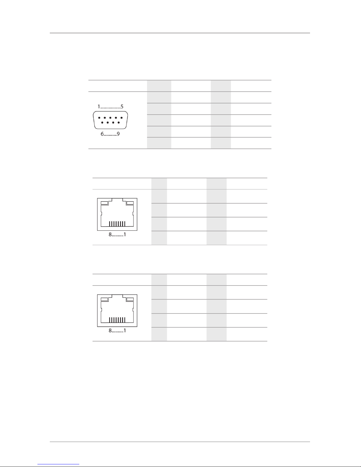
Page 76
724-746-5500 | blackbox.com
ACX048 API manual
Chapter 7: Specifications
7.4 Connector Pinouts
Table 7-36. DB9 connector.
Picture Pin Signal Color Signal
1 Not connected 6 DTR
2 CTS 7 TxD
3 RTS 8 RxD
4 DSR 9 Not connected
5 GND — —
Table 7-37. RJ-45 connector.
Picture Pin Signal Color Signal
1 D1+ 5 Not connected
2 D1- 6 D2-
3 D2+ 7 Not connected
4 Not connected 8 Not connected
Table 7-38. RJ-45 connector (serial).
Picture Pin Signal Color Signal
1 DC D 5 RxD
2 DSR 6 TxD
3 RTS 7 CTS
4 GND 8 DTR
Page 77

Page 77
724-746-5500 | blackbox.com
ACX048 API manual
Chapter 8: Troubleshooting
8. Troubleshooting
In Chapters 8–9, support for problems with the DKM FX API is provided. If you
have problems with the involved devices, especially the DKM matrix, refer to the
respective device manuals.
8.1 Network Error
Diagnosis: Network settings are not accepted after editing.
Possible Reason: Restart of the matrix not yet completed.
Measure: Do a restart.
8.2 Failure at the Matrix
Diagnosis: Serial control impossible or only possible with restrictions.
Possible Reason: Different Baud rate of CPU and matrix.
Measure: Adapt Baud rate in the CPU.
Diagnosis: Serial control via RJ-45 port not possible.
Possible Reason: Wrong network cable.
Measure: Use a crossed network cable.
Page 78

Page 78
724-746-5500 | blackbox.com
ACX048 API manual
Chapter 9: Technical Support
9. Technical Support
Before contacting technical support, please ensure you have read this manual, and
then installed and set up your DKM FX as recommended. Contact Black Box
Technical Support at 724-746-5500 or info@blackbox.com.
Support Checklist
To efficiently handle your request it is necessary to provide us with complete
information for support and problem cases. Keep the following information
available before you call:
• Company, name, phone number and e-mail.
• Type and serial number of the device (see bottom of device).
• Date and number of sales receipt, name of dealer if necessary.
• Issue date of the existing manual.
• Nature, circumstances, and duration of the problem.
• Involved components (such as graphics source/CPU, OS, graphics card, monitor,
USB-HID/USB 2.0 devices, interconnect cable) including manufacturer and
model number.
• Results from any testing you have done.
Page 79

Page 79
724-746-5500 | blackbox.com
ACX048 API manual
Chapter 10: Glossary
10. Glossary
The following terms are commonly used in this guide or in video and KVM
technology:
AES/EBU: Digital audio standard that is officially known as AES3 and that is used
for carrying digital audio signals between devices.
CATx : Any CAT5e (CAT6, CAT7) cable
CGA: The Color Graphics Adapter (CGA) is an old analog graphic standard with
up to 16 displayable colors and a maximum resolution of 640x400 pixels.
Component Video: The Component Video (YPbPr) is a high-quality video
standard that consists of three independently and separately transmittable video
signals, the luminance signal and two color difference signals.
Composite Video: The Composite Video is also called CVBS and it is part of the
PAL TV standard.
CON Unit: Component of a DKM FX or Media Extender to connect to the console (monitor(s), keyboard and mouse; optionally also with USB 2.0
devices).
Console: Keyboard, mouse, and monitor.
CPU Unit: Component of a DKM FX or Media Extender to connect to a source
(computer, CPU).
CVBS: The analog color video baseband signal (CVBS) is also called Composite
Video and it is part of the PAL TV standard.
DDC: The Display Data Channel (DDC) is a serial communication interface
between monitor and source (computer, CPU). It allows a data exchange via
monitor cable and an automatic installation and configuration of a monitor driver
by the operating system.
Dual Access: A system to operate a source (computer, CPU) from two consoles.
Dual-Head: A system with two video connections.
Dual Link: A DVI-D interface for resolutions up to 2560x2048 by signal
transmission of up to 330 Mpixel/s (24-bit)
DVI: Digital video standard, introduced by the Digital Display Working Group
(http://www.ddwg.org). Single Link and Dual Link standard are distinguished. The
signals have TMDS level.
Page 80

Page 80
724-746-5500 | blackbox.com
ACX048 API manual
Chapter 10: Glossary
DVI-I: A combined signal (digital and analog) that allows running a VGA monitor
at a DVI-I port – in contrast to DVI-D (see DVI).
EGA: The Enhanced Graphics Adapter (EGA) is an old analog graphic standard,
introduced by IBM in 1984. A D-Sub 9 connector is used for connection.
Fiber: Single-mode or multimode fiber cables.
KVM: Keyboard, video, and mouse.
Mini-XLR: Industrial standard for electrical plug connections (3-pole) for the
transmission of digital audio and control signals.
Multimode: 62.5µ multimode fiber cable or 50µ multimode fiber cable
OSD: The on-screen display is used to display information or to operate a device.
Quad-Head: A system with four video connections.
RCA (Cinch): A non-standardized plug connection for transmission of electrical
audio and video signals, especially with coaxial cables
SFP: SFPs (Small Form Factor Pluggable) are pluggable interface modules for
Gigabit connections. SFP modules are available for CATx and fiber interconnect
cables.
S/PDIF: A digital audio interconnect that is used in consumer audio equipment
over relatively short distances.
Single-Head: A system with one video connection.
Single Link: A DVI-D interface for resolutions up to 1920x1200 by signal
transmission of up to 165 Mpixel/s (24-bit). Alternative frequencies are Full HD
(1080p), 2K HD (2048x1080) and 2048x1152.
Single-mode: 9µ single-mode fiber cable.
S-Video (Y/C): The S-Video (Y/C) is a video format transmitting luminance and
chrominance signals separately. Thereby it has a higher quality standard than
CVBS.
TOSLINK®: Standardized fiber connection system for digital transmission of audio
signals (F05 plug connection).
Triple -Head: A system with three video connections.
Page 81

Page 81
724-746-5500 | blackbox.com
ACX048 API manual
Chapter 10: Glossary
USB-HID: USB-HID (USB Human Interface Devices) allow for data input.
There is no need for a special driver during installation; “New USB-HID device
found” is reported.
Typical HID devices include keyboards, mice, graphics tablets, and touchscreens.
Storage, video and audio devices are not HID.
VGA: Video Graphics Array (VGA) is a computer graphics standard with a typical
resolution of 640x480 pixels and up to 262,144 colors. It can be seen as a
follower of the graphics standards MDA, CGA and EGA.
API-Specific Glossary
ACK: Since packet transfer is not reliable, a technique known as positive
acknowledgment with retransmission is used to guarantee reliability of packet
transfers.
API: An application programming interface (API) is a specification intended to be
used as an interface by software components to communicate with each other.
An API may include specifications for routines, data structures, object classes, and
variables.
Echo: The response of the DKM FX matrix to an external command (optional).
NACK: A transmission control character sent by a station as a negative response
to the station with which the connection has been set up.
Serial: In telecommunication and computer science, serial communication is the
process of sending data one bit at a time, sequentially, over a communication
channel or computer bus.
TCP/IP: The Internet protocol suite is the set of communication protocols used for
the Internet and similar networks and generally the most popular protocol stack
for wide area networks.
Page 82

Page 82
724-746-5500 | blackbox.com
ACX048 API manual
NOTES
Page 83

Page 83
724-746-5500 | blackbox.com
ACX048 API manual
NOTES
Page 84

Black Box Tech Support: FREE! Live. 24/7.
Tech support the
way it should be.
Great tech support is just 30 seconds away at
724-746-5500 or blackbox.com.
724-746-5500 | blackbox.com
ACX048 API manual, version 1
About Black Box
Black Box provides an extensive range of networking and infrastructure products.
You’ll find everything from cabinets and racks and power and surge protection
products to media converters and Ethernet switches all supported by free, live 24/7
Tech support available in 30 seconds or less.
© Copyright 2013. Black Box Corporation. All rights reserved.
 Loading...