

Page 1

ACX1T Series
ACX1R Series
ServSwitch DKM Compact Extenders
Increase the distance between a source (computer,
CPU) and its console (keyboard, monitor, mouse,
and other peripheral devices).
Models available for CATx or fiber.
Customer
Support
Information
AC X1T
Order toll-free in the U.S.: Call 877-877-BBOX (outside U.S. call 724-746-5500)
FREE technical support 24 hours a day, 7 days a week: Call 724-746-5500 or fax 724-746-0746
Mailing address: Black Box Corporation, 1000 Park Drive, Lawrence, PA 15055-1018
Web site: w ww.blackbox.com • E-mail : info@blackbox.com
Page 2

724-746-5500 | blackbox.com
Trademarks Used in this Manual
Trademarks Used in this Manual
Black Box and the Double Diamond logo are registered trademarks, and ServSwitch is a trademark, of BB Technologies, Inc.
Mac is a registered trademark of Apple Inc.
TOSLINK is a registered trademark of Toshiba Corp.
Any other trademarks mentioned in this manual are acknowledged to be the property of the trademark owners.
We‘re here to help! If you have any questions about your application
or our products, contact Black Box Tech Support at 724-746-5500
or go to blackbox.com and click on “Talk to Black Box.”
You’ll be live with one of our technical experts in less than 30 seconds.
Page 2
724-746-5500 | blackbox.com
AC X1T
Page 3

FCC and IC RFI Statements/WEEE/RoHS
Federal Communications Commission and Industry Canada Radio Frequency Interference
Statements
This equipment generates, uses, and can radiate radio-frequency energy, and if not installed and used properly, that is, in strict
accordance with the manufacturer’s instructions, may cause inter ference to radio communication. It has been tested and found to
comply with the limits for a Class A computing device in accordance with the specifications in Subpart B of Part 15 of FCC rules,
which are designed to provide reasonable protection against such interference when the equipment is operated in a commercial
environment. Operation of this equipment in a residential area is likely to cause interference, in which case the user at his own
expense will be required to take whatever measures may be necessary to correct the interference.
Changes or modifications not expressly approved by the party responsible for compliance could void the user’s authority to
operate the equipment.
This digital apparatus does not exceed the Class A limits for radio noise emis sion from digital apparatus set out in the Radio
Interference Regulation of Industry Canada.
Le présent appareil numérique n’émet pas de bruits radioélectriques dépassant les limites applicables aux appareils numériques de
la classe A prescrites dans le Règlement sur le brouillage radioélectrique publié par Industrie Canada.
WEEE
The manufacturer complies with the EC Directive 2002/96/EG on the prevention of waste electrical and electronic equipment
(WEEE). The device labels carry a respective marking.
RoHS
This device complies with the EC Directive 2002/95/EG on the Restriction of the use of certain Hazardous Substances in electrical
and electronic equipment (RoHS).
AC X1T
724-746-5500 | blackbox.com
Page 3
Page 4

724-746-5500 | blackbox.com
NOM Statement
Instrucciones de Seguridad
(Normas Oficiales Mexicanas Electrical Safety Statement)
1. Todas las instrucciones de seguridad y operación deberán ser leídas antes de que el aparato eléctrico sea operado.
2. Las instrucciones de seguridad y operación deberán ser guardadas para referencia futura.
3. Todas las advertencias en el aparato eléctrico y en sus instrucciones de operación deben ser respetadas.
4. Todas las instrucciones de operación y uso deben ser seguidas.
5. El aparato eléctrico no deberá ser usado cerca del agua—por ejemplo, cerca de la tina de baño, lavabo, sótano mojado o cerca
de una alberca, etc.
6. El aparato eléctrico debe ser usado únicamente con carritos o pedestales que sean recomendados por el fabricante.
7. El aparato eléctrico debe ser montado a la pared o al techo sólo como sea recomendado por el fabricante.
8. Servicio—El usuario no debe intentar dar servicio al equipo eléctrico más allá a lo descrito en las instrucciones de operación.
Todo otro servicio deberá ser referido a personal de servicio calificado.
9. El aparato eléctrico debe ser situado de tal manera que su posición no interfiera su uso. La colocación del aparato eléctrico
sobre una cama, sofá, alfombra o superficie similar puede bloquea la ventilación, no se debe colocar en libreros o gabinetes
que impidan el flujo de aire por los orificios de ventilación.
10. El equipo eléctrico deber ser situado fuera del alcance de fuentes de calor como radiadores, registros de calor, estufas u otros
aparatos (incluyendo amplificadores) que producen calor.
11. El aparato eléctrico deberá ser connectado a una fuente de poder sólo del tipo descrito en el instructivo de operación, o como
se indique en el aparato.
12. Precaución debe ser tomada de tal manera que la tierra fisica y la polarización del equipo no sea eliminada.
13. Los cables de la fuente de poder deben ser guiados de tal manera que no sean pisados ni pellizcados por objetos colocados
sobre o contra ellos, poniendo particular atención a los contactos y receptáculos donde salen del aparato.
14. El equipo eléctrico debe ser limpiado únicamente de acuerdo a las recomendaciones del fabricante.
15. En caso de existir, una antena externa deberá ser localizada lejos de las lineas de energia.
16. El cable de corriente deberá ser desconectado del cuando el equipo no sea usado por un largo periodo de tiempo.
17. Cuidado debe ser tomado de tal manera que objectos liquidos no sean derramados sobre la cubierta u orificios de ventilación.
18. Servicio por personal calificado deberá ser provisto cuando:
A: El cable de poder o el contacto ha sido dañado; u
B: Objectos han caído o líquido ha sido derramado dentro del aparato; o
C: El aparato ha sido expuesto a la lluvia; o
D: El aparato parece no operar normalmente o muestra un cambio en su desempeño; o
E: El aparato ha sido tirado o su cubierta ha sido dañada.
Page 4
724-746-5500 | blackbox.com
AC X1T
Page 5

Safety Instructions
Safety Instructions
To ensure reliable and safe long-term operation of your DKM Compact Extender, please note the following guidelines:
Installation
• Only use in dry, indoor environments.
• The DKM Compact Extender and the power supply units can get warm. Do not situate them in an enclosed space without any
airflow.
• Do not place the power supply directly on top of the device.
• Do not obscure ventilation holes.
• Only use power supplies originally supplied with the product or manufacturer-approved replacements. Do not use a power
supply if it appears to be defective or has a damaged case.
• Connect all power supplies to grounded outlets. In each case, make sure that the ground connection is maintained from the
outlet socket through to the power supply's AC power input.
• Do not connect the link interface to any other equipment, particularly network or telecommunications equipment.
• Take any required ESD precautions.
Repair
• Do not attempt to open or repair a power supply unit.
• Do not attempt to open or repair the DKM Compact Extender. There are no user-serviceable parts inside.
• If there is a fault, contact Black Box Technical Support at 724-746-5500 or info@blackbox.com.
AC X1T
724-746-5500 | blackbox.com
Page 5
Page 6

724-746-5500 | blackbox.com
Table of Contents
Contents
1. Specifications........................................................................................................................................................................ 8
1.1 I nter fa ce s ....................................................................................................................................................................... 8
1.1.1 DVI-D Single Link ................................................................................................................................................ 8
1.1.2 DVI-I Single Link .................................................................................................................................................. 8
1.1.3 USB-HID .............................................................................................................................................................. 8
1.1.4 USB 2.0 (transparent) .......................................................................................................................................... 8
1.1.5 RJ-45 (Interconnect) ........................................................................................................................................... 8
1.1.6 Fiber SFP Type LC (Interconnect) ......................................................................................................................... 9
1.1.7 S erial Inter face .................................................................................................................................................... 9
1.1.8 Analog Audio Interface ....................................................................................................................................... 9
1.1.9 Digital Audio Interface ...................................................................................................................................... 10
1.2 Interconnect Cable .......................................................................................................................................................11
1.2.1 CATx ..................................................................................................................................................................11
1.2.2 Fiber .................................................................................................................................................................. 12
1.3 Supported Peripherals ................................................................................................................................................. 13
1.3.1 USB-HID Devices ............................................................................................................................................... 13
1.3.2 USB 2.0 Devices ................................................................................................................................................ 13
1.4 Connector Pinouts ....................................................................................................................................................... 13
1.5 Power Supply............................................................................................................................................................... 18
1.6 Environmental Conditions ............................................................................................................................................ 18
1.7 Size ......................................................................................................................................................................... 18
1.8 Shipping Weight .......................................................................................................................................................... 18
2. Overview ......................................................................................................................................................................... 19
2.1 Application .................................................................................................................................................................. 19
2.2 System Overview ......................................................................................................................................................... 19
2.3 Product Range ............................................................................................................................................................. 20
2.3.1 DKM Compact Transmitter and Receiver Units (CATx) ...................................................................................... 20
2.3.2 DKM Compact Transmitter and Receiver Units (Fiber) ...................................................................................... 21
2.3.3 Upgrade Kits ..................................................................................................................................................... 21
2.3.4 Accessories ....................................................................................................................................................... 22
2.4 Device Views ............................................................................................................................................................... 22
2.4.1 ACX1T-11- C/ACX1R-11- C ( Single - Head, CATx) ................................................................................................. 22
2.4.2 ACX1T-11-SM/ACX1R-11-SM (Single-Head, Fiber) ............................................................................................. 23
2.4.3 ACX1T-12A-C/ACX1R-12A-C (Analog Audio/ Serial, CATx) ............................................................................... 24
2.4.4 ACX1T-12A-SM/ACX1R-12A-SM (Analog Audio/Serial, Fiber) ........................................................................... 25
2.4.5 ACX1T-12D-C/ACX1R-12D-C ( Digital Audio, CATx) .......................................................................................... 26
2.4.6 ACX1T-12D-SM/ACX1R-12D-SM (Digital Audio, Fiber) ...................................................................................... 27
2.4.7 ACX1T-13-C/ACX1R-13-C (USB 2.0 CATx) ........................................................................................................ 28
2.4.8 ACX1T-13-SM/ACX1R-13-SM (USB 2.0 Fiber) .................................................................................................... 29
2.4.9 ACX1T-11V-C/ACX1R-11V-C ( CATx with VGA ) .................................................................................................. 30
2.4.10 ACX1T-11V-SM/ACX1R-11V-SM (Fiber with VGA) ............................................................................................. 31
2.4.11 ACX1T-22-C/ACX1R-22-C ( Dual-Head CATx ) .................................................................................................... 32
2.4.12 ACX1T-22-SM/ACX1R-22-SM (Dual-Head Fiber) ............................................................................................... 33
2.5 Status LEDs .................................................................................................................................................................. 34
2.5.1 Status Digital Audio (Option) ............................................................................................................................ 35
2.5.2 Status USB-HID Add-On (Option) ..................................................................................................................... 36
2.5.3 Status USB 2.0 (Option) .................................................................................................................................... 37
2.5.4 Status VGA/DVI-I (Option) ................................................................................................................................ 38
Page 6
724-746-5500 | blackbox.com
AC X1T
Page 7

Table of Contents
3. Installation ...................................................................................................................................................................... 39
3.1 Package Contents ........................................................................................................................................................ 39
3.2 System Setup ............................................................................................................................................................... 40
3.2.1 KVM Extender Setup ..................................................................................................................................... 40
3.2.2 Setup of Optional Modules ............................................................................................................................ 41
3.3 Example Applications .................................................................................................................................................. 42
4. Configuration .....................................................................................................................................................................44
4.1 Transmission Parameters ..............................................................................................................................................44
4.2 DDC Settings ............................................................................................................................................................... 44
4.3 Command Mode ......................................................................................................................................................... 44
5. Operation ......................................................................................................................................................................46
6. Troubleshooting ................................................................................................................................................................. 47
6.1 Blank Screen ................................................................................................................................................................ 47
6.2 USB-HID ...................................................................................................................................................................... 48
6.3 Serial Connection ........................................................................................................................................................ 49
6.4 Analog Audio ............................................................................................................................................................... 49
6.5 Digital Audio ............................................................................................................................................................... 50
6.6 USB-HID Add-On .........................................................................................................................................................51
6.7 USB 2.0 Upgrade Module ........................................................................................................................................... 52
7. Technical Support ............................................................................................................................................................... 53
7.1 Contacting Black Box................................................................................................................................................... 53
7.2 Shipping and Packaging .............................................................................................................................................. 53
8. Glossary ......................................................................................................................................................................54
AC X1T
724-746-5500 | blackbox.com
Page 7
Page 8

724-746-5500 | blackbox.com
Chapter 1: Specifications
1. Specifications
1.1 Interfaces
1.1.1 DVI-D Single Link
The video interface supports the DVI-D protocol. All signals that comply with the DVI-D Single-Link specification can be
transmitted. This includes, for example, monitor resolutions such as 1920 x 1200 @ 60 Hz, Full HD (1080p), or 2K HD (up to
2048 x 1152). Data rate is limited to 165 Megapixels per second (MPixel/s).
1.1.2 DVI-I Single Link
The video interface supports the DVI-I protocol. All analog (VGA) or digital (DVI) signals that comply with the DVI-I Single-Link
specification can be transmitted. This includes monitor resolutions for VGA up to 1920 x 1200 @ 60 Hz, and monitor resolutions
for DVI-I up to Full HD (1080p) or for DVI-D 2K HD (up to 2048 x 1152). Data rate is limited to 165 MPixel/s.
NOTE: Transmission of interlaced video signals, such as 1920 x 1080i, cannot be guaranteed.
1.1.3 USB-HID
Our devices with an USB-HID interface support a maximum of two devices compliant with the USB-HID protocol. Each USB-HID
port provides a maximum current of 100 mA.
Keyboard
Compatible with most USB keyboards. Certain keyboards with additional functions may require custom firmware to operate.
Keyboards with an integral USB hub (such as Mac® keyboards) are also supported.
Mouse
Compatible with most 2-button, 3-button, and scroll mice.
Other USB-HID devices
The proprietary USB emulation also supports certain other USB-HID devices, such as specific touch screens, graphics tablets,
barcode scanners or special keyboards. Support cannot be guaranteed, however, for every USB-HID device.
NOTE: Only two USB-HID devices are supported concurrently, such as keyboard and mouse or keyboard and touch screen. A hub
is allowed, but it does not increase the number of HID devices allowed. You can also use Extenders with an addiitonal HID
channel.
To support other USB ”non-HID” devices, such as scanners, Web cams, or memory devices, choose our devices with transparent
USB support.
1.1.4 USB 2.0 (transparent)
DKM Modular Extender models with transparent USB 2.0 support allow the connection of all types of USB 2.0 devices (without
restriction). USB 2.0 data transfer is supported with high-speed USB (max. 480 Mbps).
Each USB 2.0 port provides a maximum current of 500 mA (high power).
1.1.5 RJ-45 (Interconnect)
For CATx device communications, the extender requires a 1000BASE-T connection.
Connector wiring must comply with EIA/TIA-568-B (1000BASE-T), with RJ-45 connectors at both ends. All four cable wire pairs
are used.
NOTE: DKM Extenders do not support TCP/IP protocol: Do not run the extenders through network equipment such as routers,
switches, or hubs.
Page 8
724-746-5500 | blackbox.com
AC X1T
Page 9

Chapter 1: Specifications
1.1.6 Fiber SFP Type LC (Interconnect)
The communication of fiber devices is performed via Gigabit SFPs that have to be connected to suitable fibers fitted with type LC
connectors (see Chapter 1.2.2).
NOTE: The correct function of the device can only be guaranteed with SFPs provided by Black Box.
CAUTION: SFP modules can be damaged by electrostatic discharge (ESD).
When handling, take care not to damage devices.
1.1.7 Serial Interface
The serial interface option supports a full-duplex transmission with a real hardware handshake up to a baud rate of 19,200.
The CON Unit is cabled as DTE (Data Terminal Equipment, such as CPU output) and can be connected directly to DCE (Data
Communication Equipment) devices.
• A touch screen can be connected directly to the CON Unit.
• To connect to a serial printer (or any other DTE instead of DCE device), you need a null-modem cable (cross-over cable)
between the CON Unit and the device.
Operation of several devices:
The serial interface transmits six signals (three for each direction). Normally, four of the six signals are handshake signals (in
addition to RxD and TxD). The following configurations, however, are possible using special adapter splitting cables:
• Three single 2-wire transmissions.
• Two transmissions with a handshake signal.
• A serial mouse and a single 2-wire transmission.
In this case, choose X-ON/X-OFF software handshake for traffic control at the printer and PC.
Table 1-1. Serial interface specifications.
Specification Description
Connection Format DTE (Data Terminal Equipment)
Speed Up to 19,200 baud
Data Format Format independent
Data Transmission
Traffic Control
• RxD (Receive Data)
• TxD (Transmit Data)
The following signals are transmitted (hardware handshake):
• RTS (Request to Send)
• CTS (Clear to Send)
• DTR ( Data Terminal Ready)
• DSR ( Data Set Ready)
1.1.8 Analog Audio Interface
The Analog Audio option supports a bidirectional stereo audio transmission, in nearly CD quality.
The audio interface is a “line level” interface and it is designed to transmit the signals of a sound card (or another “line level”
device) as well as to allow the connection of active speakers to the CON Unit.
AC X1T
724-746-5500 | blackbox.com
Page 9
Page 10

724-746-5500 | blackbox.com
Chapter 1: Specifications
Stereo audio can be transmitted bidirectionally at the same time.
Connection of a microphone:
Connect the microphone to the “audio” input of the CON Unit. There are two ways to establish this connection:
• The output of the CPU Unit is connected with the microphone input of the sound card (red). Adjust the sound card to provide
an additional amplification (20 dB).
• The output of the CPU Unit is connected to the audio input of the sound card (blue). Choose this connection if the microphone
has its own pre-amplifier.
NOTE: The CON Unit can do the pre-amplification of the microphone as well. Open the CON Unit, locate the “MIC” jumper on
the audio board and close the pins.
Table 1-2. Analog audio specifications.
Specification Description
Transmission Format Digitized virtually CD quality audio (16-bit, 38.4 kHz)
Signal Level Line-level (5-volt pk-pk maximum)
Input Impedance 47 kOhm
Connections CPU Unit (2) 3.5-mm stereo audio plug (audio in and audio out)
Connections CON Unit (2) 3.5-mm stereo audio plug (audio in and audio out)
1.1.9 Digital Audio Interface
The digital audio option supports the unidirectional transmission of digital audio data.
Up to three sources can be connected to the CPU Unit. The active source is transmitted. If several sources are active, the XLR
signal takes priority, otherwise the first active signal.
Up to three sinks can be connected to the CON Unit. The signal is available at all outputs concurrently.
DKM Compact Extenders with digital audio option include a built-in sample rate converter that provides predefined sample
frequencies at the CON unit’s output.
The user can set the following parameters directly via a configuration file:
• Activate or deactivate sample rate converter
• Set sample frequency of the sample rate converter. The following sample frequencies are available:
– 32.0 kHz
– 44.1 kHz
– 48.0 kHz
– 96.0 kHz
Page 10
724-746-5500 | blackbox.com
AC X1T
Page 11

Chapter 1: Specifications
Table 1-3. Digital audio interface specifications.
Specification Description
Compatibility AES/ EBU, S /PDIF, EIAJCP1201, IEC 60958
Standards Dolby digital, DTS, PCM
• Mini XLR (AES/ EBU; symmetrical lockable)
CPU Unit (Input s)
CON Unit ( Outputs)
1.2 Interconnect Cable
1.2.1 CATx
NOTE: A point-to-point connection is required. Operation with several patch fields is possible. Routing is only supported using
ServSwitch DKM or ServSwitch DKM FX. Contact Black Box Technical Support at 724-746-5500 or info@blackbox.com.
Routing over an active network component, such as an Ethernet hub, router, or switch, is not allowed.
• Coaxial (S/ PDIF; RCA, Cinch)
• Optical (S/PDIF, TOSLINK
• Mini XLR (AES/ EBU; symmetrical, lockable)
• Coaxial (S/ PDIF, RCA, Cinch
• Optical (S/PDIF, TOSLINK)
®
)
• Avoid routing CATx cables along power cables.
• If the site has 3-phase AC power, make sure that CPU Unit and CON Unit are on the same phase.
CAUTION: To maintain regulatory EMC compliance, you must use correctly installed shielded CATx cable throughout the
interconnection link. Also, all CATx cables need to carry ferrites on both cable ends close to the device.
Type of Interconnect Cable
The DKM Compact Extender requires interconnect cabling specified for Gigabit Ethernet (1000BASE-T). The use of solid-core
(24 AWG), shielded, CAT5e (or better) is recommended.
Table 1-4. CATx interconnect cable specifications.
Parameter Description
CATx solid-core cable 24 AWG
CATx patch cable 26/ 8 AWG
S/UTP (CAT5e) cable according to EIA/TIA-568-B. Four pairs of 24
AWG wires. Connection according to EIA /TIA-568-B (1000BASE-T).
S/UTP (CAT5e) cable according to EIA/TIA-568-B. Four pairs of 26/8
AWG wires. Connection according to EIA /TIA-568-B (1000BASE-T).
NOTE: You can use flexible cables (patch cables) type 26/8 AWG; but you’ll only get half the maximum possible
extension distance (Table 1-5).
AC X1T
724-746-5500 | blackbox.com
Page 11
Page 12

724-746-5500 | blackbox.com
Chapter 1: Specifications
Maximum Acceptable CATx Cable Length
Table 1-5. Maximum acceptable CATx cable length.
Cable Type Maximum Length
Solid-conductor CATx cable 400 feet (140 m)
Stranded- conductor CATx cable 200 feet (70 m)
1.2.2 Fiber
A point-to-point connection is necessary. Operation with multiple patch panels is allowed. Routing over active network
components, such as Ethernet hubs, switches, or routers, is not allowed.
Type of Interconnect Cable
(Cable notations according to VDE)
Table 1-6. Fiber cable specifications.
Cable Type Description
Single-mode fiber 9 µm
Multimode fiber 50 µm
Multimode fiber 62.5 µm
• Two 9-µm fibers
• Indoor patch cable (EFN310-xxM -LCLC)
• Two 50-µm fibers
• Indoor patch cable (EFN6020-xxxM)
• Two 62.5-µm fibers
• Indoor patch cable (EFN110-xx xM- LCLC)
Table 1-7. Maximum acceptable fiber cable length.
Cable Type Length
Single-mode fiber 9 µm 32,800 feet (10,000 m)
Multimode fiber 50 µm (OM3) 3280 feet (1000 m)
Multimode fiber 50 µm 1300 feet (400 m)
Multimode fiber 62.5 µm 650 feet (200 m)
NOTE: If you use single-mode SFPs with multimode fibers, you normally can double the maximum acceptable cable length.
Page 12
724-746-5500 | blackbox.com
AC X1T
Page 13

Chapter 1: Specifications
Connector type
The Compact Extenders have fiber LC connectors.
1.3 Supported Peripherals
1.3.1 USB-HID Devices
The DKM Modular Extender will support most USB-HID devices, including the vast majority of keyboards and mice currently on
the market. Many other kinds of HID devices such as bar-code scanners and touchscreens may also be compatible.
It is not possible to guarantee support for all available USB-HID devices. In certain cases, you may need custom firmware.
USB-HID (and other) devices that are not supported as standard will normally operate with our devices featuring transparent USB
support.
NOTE: Concurrent operation of more than two USB-HID devices is not possible even if you use a USB hub.
1.3.2 USB 2.0 Devices
DKM Modular Extender models featuring a transparent USB 2.0 connection use Extreme USB Technology. This technology
supports all types of USB 2.0 devices; however, we cannot guarantee compatibility with every device on the market. Please
contact Black Box Technical Support at 724-746-5500 or info@blackbox.com if any issues are found.
1.4 Connector Pinouts
Pin Signal Pin Signal Pin Signal
1 TMDS data 2- 9 TMDS data 1- 17 TMDS data 0-
2 TMDS data 2+ 10 TMDS data 1+ 18 TMDS data 0 +
3 TMDS data 2 GND 11 TMDS data 1 GN D 19 TMDS data 0 GND
4 not connected 12 not connected 20 not connected
5 not connected 13 not connected 21 not connected
6 DDC input (SCL) 14 +5 VDC high impedance 22 TMDS clock GND
7 DDC output (SDA) 15 GND 23 TMDS clock +
8 Internal use 16 Hot plug recogniition 24 TMDS clock -
C1 Internal use — — C3 Internal use
C2 not connected C5 GND C4 Internal use
Figure 1-1. DVI-D connector.
Table 1-8. DVI-D single-link connector pinout.
AC X1T
724-746-5500 | blackbox.com
Page 13
Page 14

724-746-5500 | blackbox.com
Chapter 1: Specifications
Connector DVI-I Single-Link
Pin Signal Pin Signal Pin Signal
1 TMDS data 2- 9 TMDS data 1- 17 TMDS data 0-
2 TMDS data 2+ 10 TMDS data 1+ 18 TMDS data 0 +
3 TMDS data 2 GND 11 TMDS data 1 GN D 19 TMDS data 0 GND
4 not connected 12 not connected 20 not connected
5 not connected 13 not connected 21 not connected
6 DDC input (SCL) 14 +5 VDC high impedance 22 TMDS clock GND
7 DDC output (SDA) 15 GND 23 TMDS clock +
8 V-sync 16 Hot plug recogniition 24 TMDS clock -
C1 Red signal — — C3 Blue signal
C2 Green signal C5 GND C4 H-sync
Figure 1-2. DVI-I connector.
Table 1-9. DVI-I single-link connector pinout.
Connector USB Type B
Figure 1-3. USB Type B connector.
Table 1-10. USB Type B connector pinout.
Pin Signal Color
1 VCC (+5 VDC) Red
2 Data - White
3 Data + Green
4 GND Black
Page 14
724-746-5500 | blackbox.com
AC X1T
Page 15

Connector USB Type A
Connector Mini USB Type B
Chapter 1: Specifications
Figure 1-4. USB Type A connector.
Table 1-11. USB Type A connector pinout.
Pin Signal Color
1 VCC (+5 VDC) Red
2 Data - White
3 Data + Green
4 GND Black
RJ-45 connector
Figure 1-5. Mini USB Type B connector.
Table 1-12. Mini USB Type B connector pinout.
Pin Signal Color
1 VCC (+5 VDC) Red
2 Data - White
3 Data + Green
4 not connected —
5 GND Black
Figure 1-6. RJ-45 connector.
Table 1-13. RJ-45 connector pinout.
AC X1T
Pin Signal Pin Signal
1 D1+ 5 D3-
2 D1- - 6 D2-
3 D2+ 7 D4+
4 D3+ 8 D4-
724-746-5500 | blackbox.com
Page 15
Page 16

724-746-5500 | blackbox.com
Chapter 1: Specifications
Fiber SFP Type LC
Power Supply
Figure 1-7. SFP Type LC connector.
Table 1-14. SFP Type LC connector pinout.
Pin Signal
1 Data OUT
2 Data IN
DB9 (Serial)
Figure 1-8. Power supply label.
Table 1-15. Power supply connector pinout.
Pin Signal
Inside VCC (+5 VDC)
Outside GND
Figure 1-9. DB9 serial connector.
Table 1-16. DB9 serial connector pinout.
Pin Signal Pin Signal
1 not connected 6 DTR
2 CTS 7 TxD
3 RTS 8 RxD
4 DSR 0 not connected
5 GND — —
Page 16
724-746-5500 | blackbox.com
AC X1T
Page 17

3.5-mm Stereo Jack Plug
RCA (Cinch)
Chapter 1: Specifications
Figure 1-10. 3.5-mm stereo jack plug.
Table 1-17. 3.5-mm stereo jack plug pinout.
Pin Signal
1 GND
2 Audio IN/ OUT L
3 Audio IN/ OUT R
Figure 1-11. RCA connector.
Mini-XLR
Table 1-18. RCA connector pinout.
Pin Signal
1 GND
2 Data IN /OUT
Figure 1-12. Mini XLR connector.
Table 1-19. Mini XLR connector pinout.
Pin Signal
1 GND
2 Data +
3 Data -
AC X1T
724-746-5500 | blackbox.com
Page 17
Page 18

724-746-5500 | blackbox.com
Chapter 1: Specifications
TOSLINK
Figure 1-13. TOSLINK connector.
Table 1-20. TOSLINK connector pinout.
Pin Signal
1 Data IN /OUT
1.5 Power Supply
Power — Per unit: 5-VDC;
Single-head devices: 800 mA max.;
Dual-head devices: 1600 mA max.;
Optional modules: Analog audio/serial 300 mA max.,
Digital audio: 300 mA max.,
USB-HID: 300 mA max.;
USB 2.0 modules: 2500 mA max.;
VGA: 900 mA max.
1.6 Environmental Conditions
Temperature Tolerance — Operating: +41 to +113° F (+5 to +45° C)
Storage Temperature: -13 to +140° F (-25 to +60° C)
Relative Humidity (Max.) — 80% non-condensing
1.7 Size
CPU Unit/CON Unit — SIngle-head-only devices: *Only ACX1T-11-xx and ACX1R-11-xx, ACX1R-11V-xxxx: 4"H x 5.6"W x 1.1"D
(10.3 x 14.3 x 2.9 cm);
Dual-head devices and single-head devices with optional modules: 4"H x 5.6"W x 1.7"D (10.3 x 14.3 x 4.3 cm)
*NOTE: Only for connection type: xx = C for CATx and xx = SM for Fiber Single-head devices.
Shipping Box — All AC1XR: 6.5"H x 6.5"W x 4.7"D (16.5 x 16.5 x 12 cm)
All AC1XT: 8.2"H x 8.2"W x 6.5"D (21 x 21 x 16.5 cm)
1.8 Shipping Weight
CPU Unit/CON Unit — Single-head-only devices: 0.7 lb. (0.3 kg);
Dual-head devices and single-head devices with optional modules: 0.9 lb. (0.4 kg)
Shipping Box — Single-head-only devices: 4 lb. (1.8 kg);
Dual-head devices and Single-head devices with optional modules: 5.1 lb. (2.3 kg)
Page 18
724-746-5500 | blackbox.com
AC X1T
Page 19

Chapter 2: Overview
2 Overview
2.1 Application
The DKM Compact Extender is used to increase the distance between a source (computer, CPU) and its console (keyboard,
mouse, and other peripheral devices). It’s designed for use with CATx (twisted-pair) interconnect cables or fiber interconnect
cables.
The DKM Compact Extender with CATx interconnect cables won’t work between buildings where you should use a fiber optic
based product instead.
The DKM Compact Extender with fiber interconnect cables also works with applications in environments that are difficult in electromagnetical aspects. Electromagnetical interference can limit the maximum distance und reliability.
The DKM Compact Extender is fully compatible with the DKM Modular Extender.
The unit is designed to work in point-to-point applications as well as through a ServSwitch DKM or ServSwitch DKM FX
crosspoint switch.
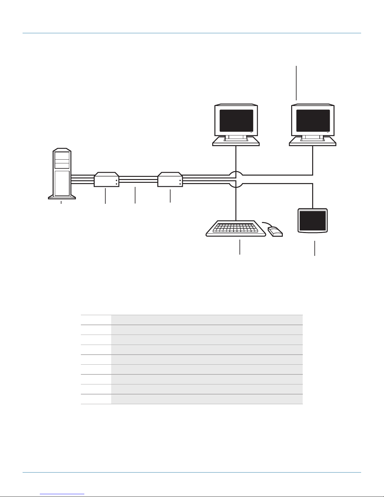
2.2 System Overview
The DKM Compact Extender consists of at least one CPU Unit and one console unit (CON Unit).
The CPU module connects directly to the source (computer, CPU) using the supplied cables. The CON unit connects to the
console (monitor, keyboard, and mouse). The CPU Unit and the CON unit communicate with each other through the interconnect
cables. Figure 2-1 shows a typical system application. Table 2-1 describes the components shown in the diagram.
6
1 2 3 4
AC X1T
5 7
Figure 2-1. System diagram.
724-746-5500 | blackbox.com
Page 19
Page 20

724-746-5500 | blackbox.com
Chapter 2: Overview
Table 2-1. System components.
Number Component
1 Source (computer, CPU)
2 DKM Modular Extender CPU unit
3 Interconnect cable
4 DKM Modular Extender CON unit
5 Console (monitor, keyboard, mouse)
6 Second monitor (option, only with dual-head devices)
7 USB-HID devices (option, only with (4) USB-HID devices)
NOTE: See Section 3.3 for installation examples.
2.3 Product Range
2.3.1 DKM Compact Transmitter and Receiver Units (CATx)
Table 2-2. CATx units.
Part Number Description
AC X1 T-11 -C Single-head transmitter (CPU) unit for (1) DVI -D single link (up to 1920 x 1200 with (2) USB-HID ports
ACX1R -11-C Single-head receiver (console [CON]) unit for (1) DVI-D single link (up to 1920 x 1200) with (2) USB-HID por ts
AC X1T-13- C Single-head transmitter (CPU) unit for DVD -I ( VGA/DVI) single link (up to 1920 x 1200) with (2) USB- HID ports, (4) USB 2.0 ports
ACX1R -13-C Single-head receiver (console [CON]) unit for DVI-I (VGA / DVI) single link (up to 1920 x 1200) with (2) USB-HI D ports, (4 ) USB 2.0 ports
AC X1 T-11V - C Single-head transmitter (CPU) unit for DVI-I (VGA/DVI) single link (up to 1920 x 1200) with (2) USB-HID ports and IR remote control
ACX1R -11V- C Single-head receiver (console [CON]) unit for DVI-I (VGA/DVI) single link (up to 1920 x 1200) with (2) USB-HID ports and IR remote control
AC X1T-12A -C Single-head transmit ter (CPU) unit for single link (up to 1920 x 1200) with (4 ) USB-HID ports, bidirectional analog audio
ACX1R -12A- C Single-head receiver (console [CON]) unit for single link (up to 1920 x 1200) with (4) USB-HID ports, bidirectional analog audio
AC X1T-12D -C Single-head transmit ter (CPU) unit for single link (up to 1920 x 1200) with (4 ) USB-HID ports, unidirectional digital audio
ACX1R12D- C Single-head transmitter (console [CON]) ) unit for single link (up to 1920 x 1200) with (4) USB-HID ports, unidirectional digital audio
ACX1T-22- C Dual-head transmitter ( CPU) unit for single link (up to 1920 x 1200) with (4) USB -HID ports, no audio
ACX1R -22-C Dual-head receiver (console [CON]) unit for single link (up to 1920 x 1200) with (4 ) USB-HID ports, no audio
Page 20
724-746-5500 | blackbox.com
AC X1T
Page 21

Chapter 2: Overview
2.3.2 ServSwitch DKM Compact Extender Transmitter and Receiver Units, Fiber
Table 2-3. Fiber units.
Part Number Description
AC X1 T-11 -SM Single-head transmitter (CPU) unit for (1) DVI -D single link (up to 1920 x 1200 with (2) USB-HID ports
ACX1R -11-SM Single-head receiver (console [CON]) unit for (1) DVI -D single link (up to 1920 x 1200 ) with (2) USB-HID ports
AC X1T-13-SM Single-head transmitter (CPU ) unit for DVD-I (VGA/ DVI) single link (up to 1920 x 1200) with (2) USB-HID ports, (4) USB 2.0 ports
ACX1R -13-SM Single-head receiver (console [CON]) unit for DVI -I ( VGA/DVI) single link (up to 1920 x 1200) with (2) USB- HID ports, (4) USB 2.0 ports
AC X1 T-11V -S M Single-head transmitter (CPU) unit for DVI-I (VGA/DVI) single link (up to 1920 x 1200) with (2) USB-HID ports and IR remote control
ACX1R -11V-SM Single-head receiver (console [CON]) unit for DVI-I (VGA/DVI) single link (up to 1920 x 1200) with (2) USB-HID ports and IR remote control
AC X1T-12A -SM Single-head transmit ter (CPU) unit for single link (up to 1920 x 1200) with (4 ) USB-HID ports, bidirectional analog audio
ACX1R -12A-SM Single-head receiver (console [CON]) unit for single link (up to 1920 x 1200) with (4) USB-HID ports, bidirectional analog audio
AC X1T-12D -SM Single-head transmit ter (CPU) unit for single link (up to 1920 x 1200) with (4 ) USB-HID ports, unidirectional digital audio
ACX1R12D-SM Single-head receiver (console [CON])) unit for single link (up to 1920 x 1200) with (4) USB- HID ports, unidirectional digital audio
ACX1T-22-S M Dual-head transmitter (CPU) unit for single link (up to 1920 x 1200) with (4) USB-HID ports, no audio
ACX1R -22-SM Dual-head receiver (console [CON]) unit for single link (up to 1920 x 1200) with (4) USB-HID ports, no audio
Part numbers for CPU Unit and CON Unit:
IMPORTANT! The part numbers for the CPU Unit and the CON Unit can be derived from the part number of the complete device.
• CPU Unit: ACX1T
• CON Unit: ACX1R
NOTE: All devices of the ACX1T/R DKM Compact Extender series are technically compatible with the devices of the DKM Modular
Extenders (ACX1MT/R series).
2.3.3 Upgrade Kits
Table 2-4. Upgrade options.
Part Number Description
ACS2209A- RMK 19"/1U rackmount kit to mount up to (3) head devices and (1) rackmount power supply (ACS2209-PS), or up to (4) devices.
ACS2209-PS 19" rackmountable power supply to feed up to (3 ) devices.
DRM VACU-S DIN Rail Mount Kit
AC X1T
724-746-5500 | blackbox.com
Page 21
Page 22

724-746-5500 | blackbox.com
Chapter 2: Overview
2.3.4 Accessories
Part Number Description
BC00200 6-foot (1.8-m) serial RS -232 cable
USB05-0006 6-foot (1.8-m) USB Type A to B cable
ACXMODH4-PS 100–240-VAC/5-VDC/5-A international power supply unit
ACXMODH2-PS 100–240-VAC/5-VDC/3-A international power supply unit
EVNDVI04-0006 6-foot (1.8-m) VGA cable (VGA to DVI-I)
EVNDVI02-0006 6-foot (1.8-m) DVI-D cable (DVI-D)
AC XS PL12 DVI-D splitter cable
EJ110-0005 5-foot (1.5-m) 3.5-mm stereo jack cable
EJ514-0005-MM 5-foot (1.5-m) RCA cable ( Cinch male connector)
EFJ04 -001M 3-foot (1-m) TOSLINK cable (F05 male connector)
Table 2-5. Accessories.
Contact Tech Support at 724-746-550 0
or info@blackbox.com.
6-foot (1.8-m) Mini-XLR cable (3-pole)
2.4 Device Views
2.4.1 ACX1T-11-C/ACX1R-11-C (Single-Head, CATx)
CPU unit, rear view CON unit, rear view
Figure 2-2. ACX1T-11-C (CPU unit) and ACX1R-11-C (CON unit).
Table 2-6. ACX1T-11-C/ ACX1R-11-C components.
CPU unit CON unit
1 Connect to 5-VDC power supply 1 Connect to 5 -VDC power supply
2 Service port 2 Service port
3 Connect to interconnect cable 3 Connect to interconnect cable
4 To CPU: USB-HI D 4 Connect to USB-HID devices
5 To CPU: DVI-D 5 Connect to DVI monitor
Page 22
724-746-5500 | blackbox.com
AC X1T
Page 23

Chapter 2: Overview
2.4.2 ACX1T-11-SM- /ACX1R-11-SM (Single-Head Fiber)
CPU unit, rear view CON unit, rear view
Figure 2-3. ACX1T-11-SM (CPU unit) and ACX1R-11-SM (CON unit).
Table 2-7. ACX1T-11-SM/ ACX1R-11-SM components.
CPU unit CON unit
1 Connect to 5-VDC power supply 1 Connect to 5-VDC power supply
2 Service port 2 Service port
3 Connect to interconnect cable 3 Connect to interconnect cable
4 To CPU: USB-HI D 4 Connect to USB-HID devices
5 To CPU: DVI-D 5 Connect to DVI monitor
AC X1T
724-746-5500 | blackbox.com
Page 23
Page 24

724-746-5500 | blackbox.com
Chapter 2: Overview
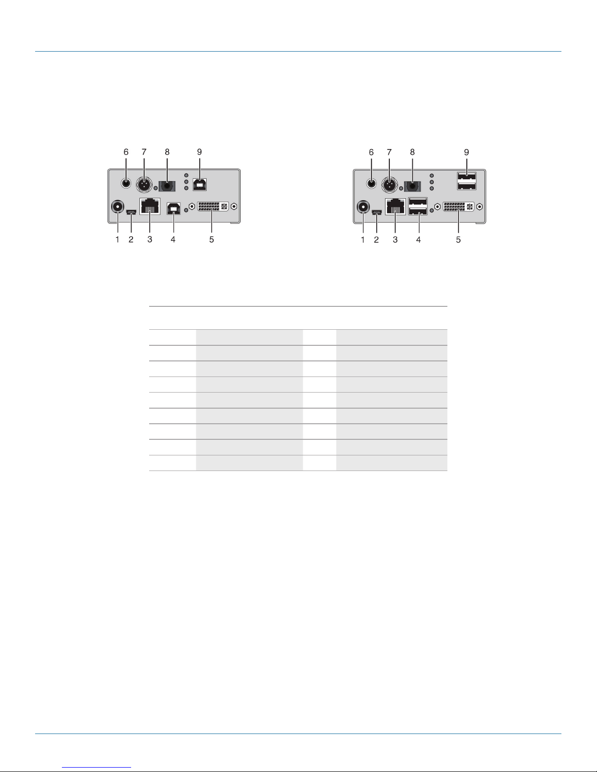
2.4.3 ACX1T-12A-C/ACX1R-12A-C (Analog Audio/Serial, CATx)
CPU unit, rear view CON unit, rear view
Figure 2-4. ACX1T-12A-C (CPU unit) and ACX1R-12A-C (CON unit).
Table 2-8. ACX1T-12A-C/ ACX1R-12A-C components.
CPU unit CON unit
1 Connect to 5-VDC power supply 1 Connect to 5-VDC power supply
2 Service port 3 Service port
3 Connect to interconnect cable 3 Connect to interconnect cable
4 To CPU: USB-HI D 1 4 Connect to USB-HID devices 1
5 To CPU: DVI-D 5 Connect to DVI monitor
6 Connect to serial (DB9 ) 6 Connect to serial (DB9)
7 Audio IN 7 Audio OUT
8 Audio OUT 8 Audio IN
9 To CPU: USB-HI D 2 9 Connect to USB-HID devices 2
Page 24
724-746-5500 | blackbox.com
AC X1T
Page 25

Chapter 2: Overview
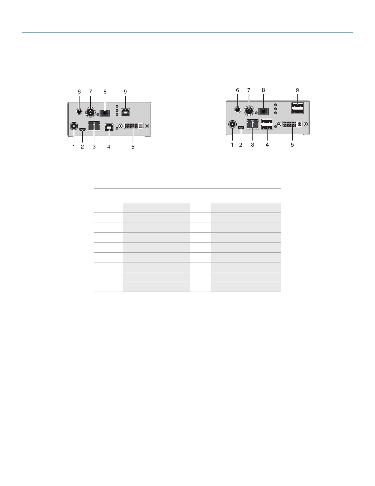
2.4.4 ACX1T-12A-SM/ACX1R-12A-SM (Analog Audio/Serial, Fiber)
CPU unit, rear view CON unit, rear view
Figure 2-5. ACX1T-12A-SM (CPU unit) and ACX1R-12A-SM (CON unit).
Table 2-9. ACX1T-12A-SM/ACX1R-12A-SM module components.
CPU unit CON unit
1 Connect to 5-VDC power supply 1 Connect to 5-VDC power supply
2 Service port 3 Service port
3 Connect to interconnect cable 3 Connect to interconnect cable
4 To CPU: USB-HI D 1 4 Connect to USB-HID devices 1
5 To CPU: DVI-D 5 Connect to DVI monitor
6 Connect to serial (DB9 ) 6 Connect to serial (DB9)
7 Audio IN 7 Audio OUT
8 Audio OUT 8 Audio IN
9 To CPU: USB-HI D 2 9 Connect to USB-HID devices 2
AC X1T
724-746-5500 | blackbox.com
Page 25
Page 26
724-746-5500 | blackbox.com
Chapter 2: Overview
2.4.5 ACX1T-12D-C/ACX1R-12D-C (Digital Audio, CATx)
CPU unit, rear view CON unit, rear view
Figure 2-6. ACX1T-12D-C (CPU unit) and ACX1R-12D-C (CON unit).
Table 2-10. ACX1T-12D-C/ACX1R-12D-C module components.
CPU unit CON unit
1 Connect to 5-VDC power supply 1 Connect to 5-VDC power supply
2 Service port 3 Service port
3 Connect to interconnect cable 3 Connect to interconnect cable
4 To CPU: USB-HI D 1 4 Connect to USB-HID devices 1
5 To CPU: DVI-D 5 Connect to DVI monitor
6 RCA input 6 RCA output
7 Mini-XLR input 7 Mini-XLR output
8 TOSLINK input 8 TOSLINK output
9 To CPU: USB-HI D 2 9 Connect to USB-HID devices 2
Page 26
724-746-5500 | blackbox.com
AC X1T
Page 27
Chapter 2: Overview
2.4.6 ACX1T-12D-SM/ACX1R-12D-SM (Digital Audio, Fiber)
CPU unit, rear view CON unit, rear view
Figure 2-7. ACX1T-12D-SM (CPU unit) and ACX1R-12D-SM (CON unit).
Table 2-11. ACX1T-12D-SM/ACX1R-12D-SM module components.
CPU unit CON unit
1 Connect to 5-VDC power supply 1 Connect to 5-VDC power supply
2 Service port 3 Service port
3 Connect to interconnect cable 3 Connect to interconnect cable
4 To CPU: USB-HI D 1 4 Connect to USB-HID devices 1
5 To CPU: DVI-D 5 Connect to DVI monitor
6 RCA input 6 RCA output
7 Mini-XLR input 7 Mini-XLR output
8 TOSLINK input 8 TOSLINK output
9 To CPU: USB-HI D 2 9 Connect to USB-HID devices 2
AC X1T
724-746-5500 | blackbox.com
Page 27
Page 28
724-746-5500 | blackbox.com
Chapter 2: Overview
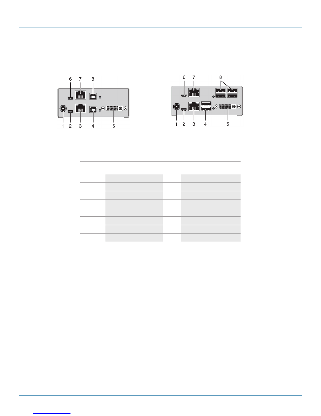
2.4.7 ACX1T-13-C/ACX1R-13-C (USB 2.0 CATx)
CPU unit, rear view CON unit, rear view
Figure 2-8. ACX1T-13-C (CPU unit) and ACX1R-13-C (CON unit).
Table 2-12. ACX1T-13-C/ACX1R-13-C module components.
CPU unit CON unit
1 Connect to 5-VDC power supply 1 Connect to 5-VDC power supply
2 Service port 1 3 Service port 1
3 Connect to interconnect cable 3 Connect to interconnect cable
4 To CPU: USB-HI D 4 Connect to USB-HID devices
5 To CPU: DVI-D 5 Connect to DVI monitor
6 Service port 2 6 Service port 2
7 Connect to interconnect cable 7 Connect to interconnect cable
8 To CPU: USB 2.0 8 Connect to USB 2.0 devices
Page 28
724-746-5500 | blackbox.com
AC X1T
Page 29

Chapter 2: Overview
2.4.8 ACX1T-13-SM/ACX1R-13-SM (USB 2.0 Fiber)
CPU unit, rear view CON unit, rear view
Figure 2-9. ACX1MT-ARH (CPU unit) and ACX1MR-ARH (CON unit).
Table 2-13. ACX1T-13-SM/ACX1R-13-SM module components.
CPU unit CON unit
1 Connect to 5-VDC power supply 1 Connect to 5-VDC power supply
2 Service port 1 3 Service port 1
3 Connect to interconnect cable 3 Connect to interconnect cable
4 To CPU: USB-HI D 4 Connect to USB-HID devices
5 To CPU: DVI-D 5 Connect to DVI monitor
6 Service port 2 6 Service port 2
7 Connect to interconnect cable 7 Connect to interconnect cable
8 To CPU: USB 2.0 8 Connect to USB 2.0 devices
AC X1T
724-746-5500 | blackbox.com
Page 29
Page 30

724-746-5500 | blackbox.com
Chapter 2: Overview
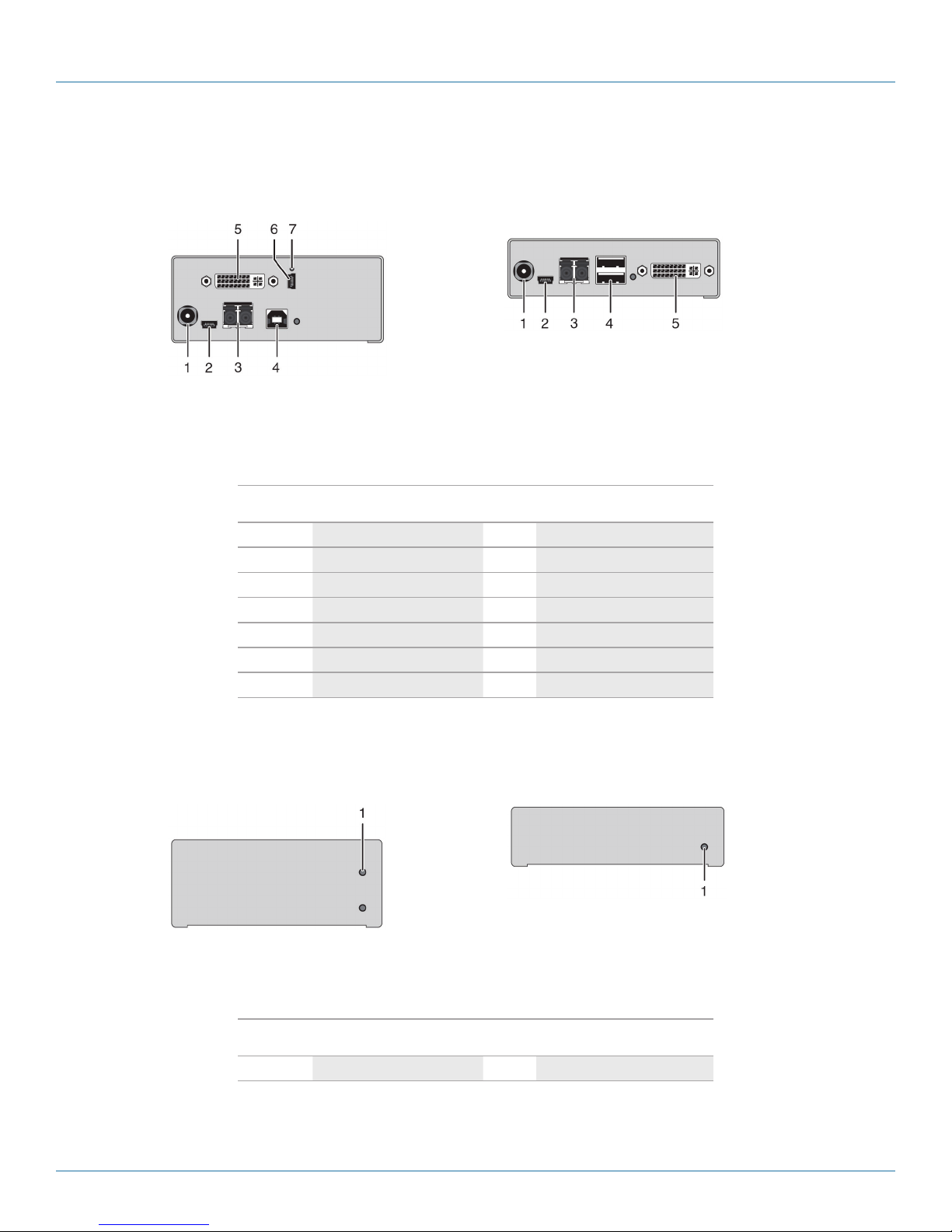
2.4.9 ACX1T-11V-C/ACX1R-11V-C (CATx with VGA)
CPU unit, rear view CON unit, rear view
Figure 2-10. ACX1T-11V-C module (CPU unit) and ACX1R-11V-C module (CON unit), rear view.
Table 2-14. ACX1T-11V-C/ACX1R-11V-C rear components.
CPU unit CON unit
1 Connect to 5-VDC power supply 1 Connect to 5-VDC power supply
2 Service port (KVM) 3 Service port
3 Connect to interconnect cable 3 Connect to interconnect cable
4 To CPU: USB-HI D 4 Connect to USB-HID devices
5 To CPU: DVI-I (VGA /DV I) 5 Connect to DVI monitor
6 Service port (DVI-U ) — —
7 IR receiver for remote control — —
CPU unit, front view CON unit, front view
Figure 2-11. ACX1T-11V-C module (CPU unit) and ACX1R-11V-C module (CON unit), front view.
Table 2-15. ACX1T-11V-C/ACX1R-11V-C front components.
CPU unit CON unit
1 IR receiver for remote control 1 IR receiver for remote control
Page 30
724-746-5500 | blackbox.com
AC X1T
Page 31
Chapter 2: Overview
2.4.10 ACX1T-11V-SM/ACX1R-11V-SM (Fiber with VGA)
CPU unit, rear view CON unit, rear view
Figure 2-12. ACX1T-11V-SM (CPU unit) and ACX1R-11V-SM (CON unit), rear view.
Table 2-16. ACX1T-11V-SM/ACX1R-11V-SM rear components.
CPU unit CON unit
1 Connect to 5-VDC power supply 1 Connect to 5-VDC power supply
2 Service port (KVM) 3 Service port
3 Connect to interconnect cable 3 Connect to interconnect cable
4 To CPU: USB-HI D 4 Connect to USB-HID devices
5 To CPU: DVI-I (VGA /DV I) 5 Connect to DVI monitor
6 Service port (DVI-U ) — —
7 IR receiver for remote control — —
CPU unit, front view CON unit, front view
Figure 2-13. ACX1T-11V-SM module (CPU unit) and ACX1R-11V-SM module (CON unit), front view.
Table 2-17. ACX1T-11V-SM/ACX1R-11V-SM front components.
CPU unit CON unit
1 IR receiver for remote control 1 IR receiver for remote control
AC X1T
724-746-5500 | blackbox.com
Page 31
Page 32

724-746-5500 | blackbox.com
Chapter 2: Overview
2.4.11 ACX1T-22-C/ACX1R-22-C (Dual-Head CATx)
CPU Module, rear view CON Module, rear view
Figure 2-14. ACX1T-22-C (CPU unit) and ACX1R-22-C (CON unit).
Table 2-18. ACX1T-22-C/ACX1R-22-C components.
CPU unit CON unit
1 Connect to 5-VDC power supply 1 Connect to 5-VDC power supply
2 Service port 1 3 Service port 1
3 Connect to interconnect cable 3 Connect to interconnect cable
4 To CPU: USB-HI D 1 4 Connect to USB-HID devices 1
5 To CPU: DVI-D 1 5 Connect to DVI monitor 1
6 Service port 2 6 Service port 2
7 Connect to interconnect cable 7 Connect to interconnect cable
8 To CPU: USB HID 2 8 Connect to USB-HID devices 2
9 To CPU: DVI-D 2 9 Connect to DVI monitor 2
Page 32
724-746-5500 | blackbox.com
AC X1T
Page 33

Chapter 2: Overview
2.4.12 ACX1T-22-SM/ACX1R-22-SM (Dual-Head Fiber)
CPU unit, rear view CON unit, rear view
Figure 2-15. ACX1T-22-SM (CPU unit) and ACX1R-22-SM (CON unit).
Table 2-19. ACX1T-22-SM/ACX1R-22-SM components.
CPU unit CON unit
1 Connect to 5-VDC power supply 1 Connect to 5-VDC power supply
2 Service port 1 3 Service port 1
3 Connect to interconnect cable 3 Connect to interconnect cable
4 To CPU: USB-HI D 1 4 Connect to USB-HID devices 1
5 To CPU: DVI-D 1 5 Connect to DVI monitor 1
6 Service port 2 6 Service port 2
7 Connect to interconnect cable 7 Connect to interconnect cable
8 To CPU: USB HID 2 8 Connect to USB-HID devices 2
9 To CPU: DVI-D 2 9 Connect to DVI monitor 2
AC X1T
724-746-5500 | blackbox.com
Page 33
Page 34

724-746-5500 | blackbox.com
Chapter 2: Overview
2.5 Status LEDs
The KVM extender has a multicolor LED on both sides to indicate overall status. It also has two additional LEDs on the back side
to indicate the connection status.
CPU Unit, CATx, rear view
CPU Unit, Fiber, rear view CON Unit, CATx or Fiber models, front view
Figure 2-16. Status LEDs on the KVM extender.
Table 2-20. LED 1 and 2: Connection Status.
Position LED Status Description
1 Failure LED (green)
2 Status LED (green)
Off Connection available
On or Flashing Connection failure (flashing for about 20 seconds following a connec tion failure)
Flashing No connection via interconnect cable
On Connection available
Table 2-21. LED 3: USB and Video Status.
Color Description
Dark Red Device ready
Red Connection available
Blue USB connection available
Green Video available
Yel low Connection and USB signal available, no video
Violet Connection and video signal available, no USB signal
Light Blue USB and video signal available, no connection
Turquoise Connection, USB, and video signal available (operating status)
Page 34
724-746-5500 | blackbox.com
AC X1T
Page 35

Chapter 2: Overview
2.5.1 Status Digital Audio (Option)
The KVM extender with optional digital audio has a multicolor LED on the front side of the CPU Unit to indicate connection
status. More information is available via on-screen display (OSD) (see the manual for the Media/DVI Converter [part number
ACS 411A -R 2] ) .
CPU unit CON unit
Figure 2-17. Status digital audio (option)
Table 2-22. LED 1: Digital Audio Status.
LED color Description
Red No signal
Cya n CPU Unit: S/PDIF signal (RCA) available
Violet CPU Unit: AES/EBU signal (Mini-XLR) available
Blue CPU Unit: S/ PDIF signal (TOSLINK) available
Green CON Unit: Signal available
AC X1T
724-746-5500 | blackbox.com
Page 35
Page 36

724-746-5500 | blackbox.com
Chapter 2: Overview
2.5.2 Status USB-HID Add-On (Option)
The KVM extender with optional USB-HID has three LEDs on the rear side to indicate the connection status:
CPU Unit, rear view CON Unit, rear view
Figure 2-18. Status upgrade modules USB-HID.
Table 2-23. LED 1, 2, and 3: Status.
Position LED Status Description
Off No USB-HID device or not supported ; USB device connected
1, 2 Device LED (orange)
3 Status LED (orange)
Flashing fast USB-HID device active
On USB- HID device ready or DKM Modular Extender in command mode
• No power supply voltage
Off
Flashing slowly CON Unit: DKM Modular Extender in command mode or no connection
Flashing fast Operating status
• CPU Unit: DKM Modular Extender in command mode or no connection
• CON Unit: Keyboard in command mode
Page 36
724-746-5500 | blackbox.com
AC X1T
Page 37

Chapter 2: Overview
2.5.3 Status USB 2.0 (Option)
The KVM extender with optional USB 2.0 has a multicolor LED on both sides to indicate overall status. It also has two more LEDs
on the back side to indicate the connection status.
CPU Unit, rear view CON Unit, rear view
Figure 2-19. Status USB 2.0 (option).
Table 2-24. LEDs 1 and 2: Status.
Position LED Status Description
1 Failure LED (green)
2 Status LED (green)
Off Connection available
On or flashing Connection failure (flashing for about 20 seconds following a connection failure)
Off No connection via interconnect cable
On Connection available
Table 2-25. LED 3: USB 2.0 Status.
LED color Description
Red Device ready
Green Only connection available, no USB 2.0 signal
Green/turquoise flashing Connection available, no USB 2.0 device connected (only CON unit)
Turquoise Connection and USB 2.0 signal available (operating status)
AC X1T
724-746-5500 | blackbox.com
Page 37
Page 38

724-746-5500 | blackbox.com
Chapter 2: Overview
2.5.4 Status VGA/DVI-I (Option)
The KVM extender with VGA/DVI-I input has a multicolor LED on the front side of the CPU unit to indicate connection status.
Figure 2-20. VGA/DVI-I option, front view, multicolor LED.
Table 2-26. LED 1: Connection Status VGA/DVI-I.
Color Description
Dark Red No video signal; monitor not detected
Red Video signal not supported; monitor not detected
Green Video signal supported; monitor not detected
Blue No video signal; monitor detected
Violet Video signal not supported; monitor detected
Light Blue Video signal supported; monitor detected
Page 38
724-746-5500 | blackbox.com
AC X1T
Page 39

Chapter 3: Installation
3. Installation
3.1 Package Contents
Your extender package contains the following items. If anything is missing or damaged, please contact Black Box Technical
Support at 724-746-5500 or info@blackbox.com.
• DKM Modular Extender pair (CPU Unit and CON Unit) in separate boxes
• (2) 5-VDC international power supply units
• (2) country-specific power cords
• Quick Start Guide
The Single-Head devices also include:
• (1) DVI video cable (6-ft. [1.8 m], DVI-D male-to-male)
Figure 3-1. DVI video cable.
• (1) USB cable (6-ft. [1.8 m], Type A to Type B)
The Dual-Head devices also include:
• DVI video cable (6-ft. [1.8-m], DVI-D male to male)
• USB cable (6-ft. [1.8-m], Type A to Type B)
The Analog Audio/Serial option also includes:
• Serial cable (6-ft. [1.8-m], RS-232 male connector)
Figure 3-2. USB cable.
Figure 3-3. DVI cable.
Figure 3-4. USB cable.
• Stereo jack cable (5.2-ft. [1.6-m], 3.5-mm male connector)
AC X1T
Figure 3-5. Serial cable.
Figure 3-6. Stereo jack cable.
724-746-5500 | blackbox.com
Page 39
Page 40

724-746-5500 | blackbox.com
Chapter 3: Installation
The Digital Audio option also includes:
• RCA cable (8.2-ft. [2.5-m], Cinch male connector)
• TOSLINK cable (6-ft. [1.8-m], F05 male connector)
The USB-HID Add-on option also includes:
• USB cable (6-ft. [1.8-m] USB Type A to Type B)
The USB 2.0 Add-on option also includes:
• USB cable (6-ft. [1.8-m], USB Type A to Type B)
Figure 3-7. RCA cable.
Figure 3-8. TOSLINK cable.
Figure 3-9. USB cable.
Figure 3-10. USB cable.
The VGA also includes (a DVI-I cable instead of a DVI-D cable):
• VGA cable (6-ft. [1.8-m], VGA male to DVI-I male)
Figure 3-11. USB cable.
• Infrared remote control
3.2 System Setup
NOTE: I f you are a first-time user, we recommend that you set up the system with the CPU Unit and the CON Unit in the same
room as a test setup. This will enable you to identify and solve any cabling problems, and experiment with your system
more conveniently.
NOTE: Verify that interconnect cables, interfaces, and handling of the devices comply with the requirements described in this
manual.
3.2.1 KVM Extender Setup
1. Switch off all devices.
CON Unit Installation
2. Connect your monitor(s), keyboard, and mouse to the CON Unit.
3. Connect the CON Unit with the interconnect cable(s).
Page 40
724-746-5500 | blackbox.com
AC X1T
Page 41

Chapter 3: Installation
4. Connect the 5-VDC power supply to the CON Unit.
CPU Unit Installation
5. Connect the source (computer, CPU) with the supplied cables to the CPU Unit. Make sure the cables are not strained.
6. Connect the CPU Unit to the interconnect cable(s).
7. Connect the 5-VDC power supply to the CPU Unit.
8. Power up the system.
NOTE: To power up the system, the following sequence is recommended: Monitor – CON Unit – CPU Unit – source.
NOTE: The KVM extender with VGA / DVI-I input is connected as mentioned above. For a complete and detailed description of
the setup and configuration of the VGA option, see the Media/DVI Converter [part number ACS411A-R2]) manual.
3.2.2 Setup of Optional Modules
You can hot-plug the modules.
Analog Audio/Serial Option:
1. Connect the audio source with the CPU Unit (for example, CPU audio output with audio input, CPU audio input with audio
output).
2. Connect the audio output at the CON Unit with headphones or suitable speakers.
3. Connect the audio input at the CON Unit with a suitable microphone.
Digital Audio Option:
1. Connect the digital audio source with the suitable audio input of the CPU unit.
2. Connect the audio output of the CON Unit with suitable speakers or audio amplifiers.
NOTE: If several active sources are connected, Mini-XLR input takes priority. The audio signal is available at all outputs.
USB-HID Add-On Option:
1. Connect the CPU with the CPU Unit (USB-HID 2).
2. Connect the USB-HID devices with the CON Unit (Connect to USB-HID device 2).
USB 2.0 Add-On Option:
1. Connect the CPU with the CPU Unit (USB 2.0).
2. Connect the USB 2.0 devices with the CON Unit (Connect to USB 2.0 devices).
AC X1T
724-746-5500 | blackbox.com
Page 41
Page 42

724-746-5500 | blackbox.com
Chapter 3: Installation
3.3 Example Applications
This section illustrates typical installations of DKM Modular Extenders:
1 2 3 4
Figure 3-12. DKM Modular Extender (Single-Head).
1 2 3 4
5
5
8
Figure 3-13. DKM Modular Extender (Single-Head with Digital/Analog Audio).
Page 42
724-746-5500 | blackbox.com
AC X1T
Page 43
Chapter 3: Installation
6
1 2 3 4
Figure 3-14. DKM Modular Extender (Dual-Head with 4x USB-HID).
Table 3-1. Components in Figures 3-12 through 3-14.
Number Description
1 Source (computer, CPU)
2 DKM Modular Extender CPU Unit
3 Interconnect cable
4 DKM Modular Extender CON Unit
5 Console (keyboard, monitor, mouse)
6 Second monitor (option, only with Dual-Head devices)
7 USB-HID devices (option, only with [4] USB-HID devices)
8 Audio sink (optional, only with devices with analog audio/serial option or digital audio option
5
7
AC X1T
724-746-5500 | blackbox.com
Page 43
Page 44

724-746-5500 | blackbox.com
Chapter 4: Configuration
4. Configuration
4.1 Transmission Parameters
The device operates with a proprietary compression method. In its default configuration, the device adapts dynamically to monitor
resolution and image content. This configuration works in almost all conditions. Modify it only if image quality is not fully
satisfactory.
NOTE: In exceptional cases, detached "frame droppings" (loss of single pictures) or color effects can appear.
4.2 DDC Settings
By default, the device sends the factory preset DDC information to the CPU. This information works in most cases.
During normal operation , you can downoad the console monitor’s DDC information (see Chapter 5: Operation).
For special requirements, DDC information can be retrieved and uploaded as a binary file at both the CPU Unit and the CON Unit.
Connect your computer with a USB Mini cable to the CPU Unit’s or CON Unit’s service port.
You can now access the data area of the unit as a flash drive “Extender.”
Uploading DDC Information
Copy the binary file containing your specific DDC information to the flash drive of the CPU Unit or CON Unit.
The current DDC information is replaced.
Retrieving DDC Information
Copy the file "DDC-EDID.bin" on the flash drive of the CPU Unit to your computer.
To open the binary file, you have to install a suitable software, for example, WinDDCwrite (Download), on your computer.
Reset to Factory DDC Information
Delete the file called “DDC-EDID.bin” on the flash drive of the CPU Unit. By deleting this file, the factory DDC Information is
restored.
4.3 Command Mode
During normal use, the console keyboard functions in the usual manner. However, for all KVM Extenders with USB-HID support,
you can set the keyboard into a Command Mode by using a specific “hotkey” sequence. While in Command Mode, several
functions are performed via keyboard commands. To exit Command Mode, press <Esc>. While in Command Mode, the LEDs
Shift and Scroll on the console keyboard will flash.
NOTE: In Command Mode, normal keyboard and mouse operation will cease. Only selected keyboard commands are available.
Table 4-1 lists the keyboard commands to enter and to exit Command Mode and to change the hotkey sequence.
Table 4-1. Keyboard commands.*
Function Keyboard Command
Enter Command Mode 2x <Left-Shift>/Hotkey
Exit Command Mode <Esc>
Change Hotkey sequence <Left-Ctrl> + <Left-Shift> + <c>, <Hotkey code>, <Enter >
*See Table 4-2 for keyboard command sequences descriptions.
Page 44
724-746-5500 | blackbox.com
AC X1T
Page 45

Chapter 4: Configuration
Table 4-2. Keyboard command sequences.
Keyboard Sequence Description
<Key> + < Key> Press keys simultaneously
<Key>, <Key> Press keys successively
2x<Key> Press key quickly, twice in a row (similar to a mouse -click)
You can change the hotkey sequence to enter Command Mode. Table 4-3 lists the hotkey codes for the available key sequences.
Table 4-3. Hotkey codes.
Hotkey Code Hotkey
1 <Left-Ctrl> + <Left-Shift> + <i>
2 2x <Scroll>
3 2x <Left-Shift>
4 2x <Left-Ctrl>
5 2x <Left-Alt>
6 2x <Right-Shift>
7 2x < Right-Ctrl>
8 2x <Right-Alt>
AC X1T
724-746-5500 | blackbox.com
Page 45
Page 46

724-746-5500 | blackbox.com
Chapter 5: Operation
5. Operation
Download of DDC Information
By default, data from the internal DDC list is reported to the source (computer, CPU). If these settings do not lead to a satisfying
result, you can download and store the console monitor’s DDC information internally. The devices must be configured accordingly
(see Section 4.2).
On all KVM Extenders with USB-HID support, the user can load the DDC information of the console monitor via keyboard
command under operating conditions.
1. Enter Command Mode with the “hotkey” (see Section 4.2).
2. Press the <a> key to download the DDC information of the console monitor.
The screen goes black for a short time.
At the same time Command Mode is closed and the keyboard LEDs return to previous status.
This re-adjusts the video mode. You should have optimal screen quality. The CPU should now show the console monitor as the
current screen, together with the available video resolutions.
The DDC information of the console monitor was loaded once.
To re-load the DDC information, repeat the operation.
During DDC transfer, the status LEDs on both CON and CPU units flash while reading (CON unit) and copying (CPU unit)
information.
Page 46
724-746-5500 | blackbox.com
AC X1T
Page 47

6. Troubleshooting
6.1 Blank Screen
Rear view Front view
Chapter 6: Troubleshooting
Figure 6-1. Blank screen.
Table 6-1. Blank screen troubleshooting.
Diagnosis Possible Reason Measure
LED 3 of f Power supply • Check power supply units and the connection to the power network.
LED 1 on or LED 2 off Connection between the CON unit and the CPU unit • Check interconnect cables and connections.
• Check DVI-D cable to CPU.
CPU unit: LED 3 red or yellow No video signal detected by source (computer, CPU)
No monitor detec ted
CON unit: LED 3 red or yellow
No video signal detected from CPU unit
• Download DDC information from console monitors (see Chapter 5).
Reboot CPU if necessary.
• Check connec tion, length, and quality of the DVI-D cable to monitor;
tighten cable thumbscrews.
• Check connection, length, and quality of the interconnect cables
between the units.
• Download DDC information from console monitors (see Chapter 5).
Reboot CPU if necessary.
AC X1T
724-746-5500 | blackbox.com
Page 47
Page 48

724-746-5500 | blackbox.com
Chapter 6: Troubleshooting
6.2 USB-HID
Rear view Front view
Figure 6-2. USB-HID.
Table 6-2. USB-HID troubleshooting.
Diagnosis Possible Reason Measure
Keyboard LEDs Shift and Scroll are blinking Keyboard in command mode • Press <Esc> to leave command mode
• Check connection of USB cable to CPU; select another USB
CPU unit: LED 3 green or violet No USB connection to CPU
CON unit: LED 3 green or violet Problems with USB connection
No USB-HID device • Connect USB-HID device.
USB device without function
USB-HID device is not suppor ted
port if necessary.
• Remove USB and power cable and restart CPU. Connect
power cable first.
• Check connec tion of USB cable to USB-HID device.
• Remove DVI and power cable and restart CON unit. Connect
power cable first.
• Contact Black Box Technical Suppor t at 724-746-5500 or
info@ blackbox.com if necessar y.
Page 48
724-746-5500 | blackbox.com
AC X1T
Page 49

6.3 Serial Connection
Table 6-3. Serial connection troubleshooting.
Diagnosis Possible Reason Measure
Settings of the serial interface • Check baud rate and general settings.
Chapter 6: Troubleshooting
Serial device not operational
Touchscreen not operational Hardware handshake • Adjust serial interface to X-ON/X-OFF software handshake.
No serial connec tion to CPU • Check connection via serial cable.
No serial connection to end device (for example,
touchscreen, keyboard)
• Connect serial end device and switch it on.
• Check connection via serial cable.
6.4 Analog Audio
Table 6-4. Analog audio troubleshooting.
Diagnosis Possible Reason Measure
• Connect analog audio source.
• Check audio cable.
• Switch analog audio source on.
• Activate analog output at CPU/audio source.
• Connect analog audio sink and switch it on.
• Check connection of audio cable.
• Connect analog audio source (microphone).
• Check connection of audio cable.
• Switch analog audio source on.
• Activate analog output at audio source.
• Check connection to CPU.
• Check connection of audio cable.
• Check audio configuration.
CON unit: No signal at audio output
CPU unit: No signal at audio output (microphone)
No audio connection to CPU/audio source
No signal
No audio connection to audio sink (for example,
speakers)
No audio connection to audio source (microphone)
No signal
No audio connection to audio sink (for example, CPU)
AC X1T
724-746-5500 | blackbox.com
Page 49
Page 50

724-746-5500 | blackbox.com
Chapter 6: Troubleshooting
6.5 Digital Audio
CPU Unit, rear view CON Unit, rear view
Figure 6-3. Digital audio option.
Table 6-5. Digital audio troubleshooting.
Diagnosis Possible Reason Measure
No audio connection to CPU/audio source
CPU unit: LED 1 red
No signal
• Connect digital audio source.
• Check connection of audio cable.
• Switch digital audio source on.
• Activate digital output at CPU/audio source.
No audio connection to audio sink (for example, speakers)
CON unit: LED 1 red
No signal • Check signal at CPU unit.
No signal/ LEDs 1 OK Digital silence at active audio source
• Connect digital audio sink.
• Check connection of audio cable.
• Check LEDs at CPU unit.
• Check audio format.
• Change audio input.
Page 50
724-746-5500 | blackbox.com
AC X1T
Page 51

Chapter 6: Troubleshooting
6.6 USB-HID Add-On
CPU Unit, rear view CON Unit, rear view
Figure 6-4. USB-HID Add-on.
Table 6-6. USB-HID Add-on troubleshooting.
Diagnosis Possible Reason Measure
• Check connection of USB cable to USB-HID device.
LEDs 1 and 2 off Device at higher/lower USB- HID port not detected
• Connect USB-HID device.
• Contact Black Box Technical Suppor t at 724-746-5500 or
info@ blackbox.com if necessar y.
CPU unit: LED 3 of f Connection bet ween CON unit and CPU unit • Check interconnet cable and connectors.
CON unit: LED 3 off Keyboard in command mode • Press <Esc> to leave command mode.
CON unit: LED 3 flashing slowly
Connection between CON unit and CPU unit • Check interconnect cable and connections.
Keyboard in command mode • Press < Esc> to leave command mode.
AC X1T
724-746-5500 | blackbox.com
Page 51
Page 52

724-746-5500 | blackbox.com
Chapter 6: Troubleshooting
6.7 USB 2.0 Upgrade Module
CPU Unit, rear view CON Unit, rear view
Figure 6-5. USB 2.0 upgrade module.
Table 6-7. USB 2.0 Upgrade Module troubleshooting.
Diagnosis Possible Reason Measure
• Check connection USB cable to CPU; select another USB port
CPU unit: All LEDs off No connection to CPU
CON unit: LED 3 red Connection between CON unit and CPU unit • Check interconnect cable and connectors.
No USB 2.0 device • Connect USB 2.0 device.
CON unit: LED 3 flashing green/turquoise and
USB 2.0 device without function
USB 2.0 device is not suppor ted
if necessa ry.
• Remove USB and power cable and restart CPU. Connect
power cable first.
• Check installation at the CPU. Also check to make sure the
CPU has the necessary drivers.
• New connection of the USB 2.0 device.
• Contact Black Box Technical Suppor t at 724-746-5500 or
info@ blackbox.com if necessar y.
Page 52
724-746-5500 | blackbox.com
AC X1T
Page 53

Chapter 7: Technical Support
7. Technical Support
7.1 Contacting Black Box
If you determine that your ServSwitch DKM Compact Extender is malfunctioning, do not attempt to alter or repair the unit. It
contains no user-serviceable parts. Contact Black Box Technical Support at 724-746-5500 or info@blackbox.com.
Before you do, make a record of the history of the problem. We will be able to provide more efficient and accurate assistance
if you have a complete description, including:
• the nature and duration of the problem.
• when the problem occurs.
• the components involved in the problem.
• any particular application that, when used, appears to create the problem or make it worse.
7.2 Shipping and Packaging
If you need to transport or ship your ServSwitch DKM Compact Extender:
• Package it carefully. We recommend that you use the original container.
• If you are returning the unit, make sure you include everything you received with it. Before you ship for return or repair,
contact Black Box to get a Return Authorization (RA) number.
AC X1T
724-746-5500 | blackbox.com
Page 53
Page 54

724-746-5500 | blackbox.com
Chapter 8: Glossary
8. Glossary
The following terms are commonly used in this guide or in video and KVM technology:
AES/EBU: Digital audio standard that is officially known as AES3. It’s used to carry digital audio signals between devices.
CATx: Any CAT5e (CAT6, CAT7) cable
CGA: The Color Graphics Adapter (CGA) is an old analog graphic standard that displays up to 16 colors and at a maximum
resolution of 640 x 400 pixels.
Component Video: The Component Video (YPbPr) is a high-quality video standard that consists of three independently and separately transmittable video signals: the luminance signal and two color difference signals.
Composite Video: The Composite Video is also called FBAS and it is part of the PAL TV standard.
CON Unit: Component of a DKM Modular Extender or Media Extender to connect to the console (monitor(s), keyboard and
mouse; optionally also with USB 2.0 devices).
CPU Unit: Component of a DKM Modular Extender or Media Extender to connect to a source (computer, CPU).
DDC: The Display Data Channel (DDC) is a serial communication interface between monitor and source (computer, CPU). It can
exchange data via a monitor cable and the operating system can install and configure a monitor driver automatically.
Access: A system to operate a source (computer, CPU) from two consoles.
Dual-Head: A system with two video connections.
Dual-Link: A DVI-D interface for resolutions up to 2560 x 2048 that transmits signals up to 330 MPixel/s (24-bit)
DVI: Digital video standard, introduced by the Digital Display Working Group (http://www.ddwg.org). Single Link and Dual Link
standard are distinguished. The signals have TMDS level.
DVI-I: A combined signal (digital and analog) that allows running a VGA monitor at a DVI-I port—in contrast to DVI-D (see DVI).
Fiber: Single-mode or multimode fiber cables.
EGA: The Enhanced Graphics Adapter (EGA) is an old analog graphics standard, introduced by IBM in 1984. It uses a DB9
connector for connection.
FBAS: The analog color video baseband signal (FBAS) is also called Composite Video and it is part of the PAL TV standard.
Console: Keyboard, mouse and monitor.
KVM: Keyboard, video and mouse.
Mini-XLR: Industrial standard for electrical plug connections (3-pole) for the transmission of digital audio and control signals.
Multimode: 62.5µ fiber cable or 50µ fiber cable
OSD: The On-Screen-Display displays information or operates a device.
Quad-Head: A system with four video connections.
RCA (Cinch): A not standardized plug connection that transmits electrical audio and video signals, especially with coaxial cables.
SFP: Small Form-Factor Pluggables (SFPs) are pluggable interface modules for Gigabit connections. SFP modules are available for
CATx and fiber interconnect cables.
S/PDIF: A digital audio interconnect that is used in consumer audio equipment over relatively short distances.
Single-Head: A system with one video connection.
Single Link: A DVI-D interface that supports resolutions up to 1920 x 1200 by transmitting signals up to 165 Megapixels per
second (24-bit). Alternative frequencies are Full HD (1080p), 2K HD (2048 x 1080), and 2048 x 1152.
Page 54
724-746-5500 | blackbox.com
AC X1T
Page 55

Chapter 8: Glossary
Single-mode: 9µ fiber cable
S-Video (Y/C): The S-Video (Y/C) is a video format that transmits luminance and chrominance signals separately. It has a higher
quality standard than FBAS.
TOSLINK: Standardized fiber connection system that digitally transmits audio signals (F05 plug connection).
Triple-Head: A system with three video connections.
USB-HID: USB-HID devices (Human Interface Device) allow for data input. There is no need for a special driver during installation;
“New USB-HID device found” is reported. Typical HID devices include keyboards, mice, graphics tablets, and touchscreens.
Storage, video, and audio devices are not HID.
VGA: Video Graphics Array (VGA) is a computer graphics standard with a typical resolution of 640 x 480 pixels and up to
262,144 colors. It follows the graphics standards MDA, CGA and EGA.
AC X1T
724-746-5500 | blackbox.com
Page 55
Page 56

Black Box Tech Support: FREE! Live. 24/7.
Tech support the
way it should be.
Great tech support is just 30 seconds away at 724-746-5500 or blackbox.com.
About Black Box
Black Box provides an extensive range of networking and infrastructure products. You’ll find everything from cabinets and racks
and power and surge protection products to media converters and Ethernet switches all supported by free, live 24/7 Tech support
available in 30 seconds or less.
© Copyright 2011. Black Box Corporation. All rights reserved.
ACX1T, version 1
724-746-5500 | blackbox.com
 Loading...