

Page 1
ACX1000 Quick Start Guide
5. Installation
5.1 Configuration
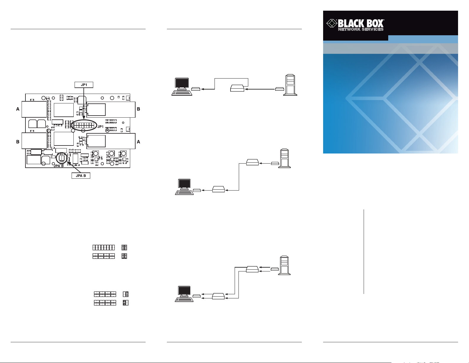
Place the repeater with the CATx/fiber connectors on the
left and the fiber connectors on the right. The main printed
circuit board will look like Figure 5.
ACX1000 Quick Start Guide
5.2.1 CATx or Fiber Repeater, Multimode/
Single-Mode Cross Repeater
Connect the local device via CATx (or fiber) Connector A and
connect the remote device via CATx (or fiber) Connector B.
Repeater
Local Device
Local
Device
CATx
Remote Device
Repeater
Figure 6. Cross repeater example.
5.2.2 CATx/Cross Repeater
Connect the local device via CATx (or fiber) Connector A.
Connect Fiber Connector B to Fiber Connector A on the
second repeater. Connect the remote device via CATx (or
fiber) Connector B.
ACX1000 ACX1000-MS
June 2010
ACX1000-MM ACX1000-DM
ACX1000-CM
Repeaters and Cross Repeaters
Use fiber to extend
the distance between
two CATx devices.
READ ME FIRST
Figure 5. Installation.
5.1.1 Operating Mode, Repeater or Cross Repeater
To change the operating mode from repeater to cross
repeater or vice versa, install optical transceivers and
reconfigure the repeater.
Table 2. Repeater or cross repeater configuration.
Operating Mode JP1 JP A B
Repeater or cross repeater
CATx/fiber cross repeater
5.1.2 Operating Mode, Dual-Head Cross Repeater
Table 3. Dual-head cross repeater configuration.
Operating Mode JP1 JP A B
Repeater or cross repeater
CATx/fiber cross repeater
5.2 Installation Instructions
Attach connectors marked with “A” to cables that link to a
local unit. Attach connectors marked with “B” to cables
that link to a remote unit.
Page 5 Page 6
Remote
Device
Repeater
CATx
Fiber
Figure 7. CATx/Cross repeater sample.
5.2.3 Dual-Head Cross-Repeater
Connect the local device’s CATx port via the connector
marked “Cross Repeater Local CATx.” Connect the remote
device’s CATx port via the connector marked “Cross
Repeater Remote CATx.”
CATx
Local
Device
Repeater
Remote
Device
Repeater
CATx
Fiber
Figure 8. Dual-head cross repeater application.
Customer
Support
Information
Order toll-free in the U.S.:
Call 877-877-BBOX
(outside U.S. call 1-724-746-5500)
FREE technical support
24 hours a day, 7 days a week:
Call 724-746-5500 or
fax 724-746-0746
Mailing address:
Black Box Corporation
1000 Park Drive
Lawrence, PA 15055-1018
Web site: www.blackbox.com
E-mail: info@blackbox.com
© Copyright 2010. Black Box Corporation. All rights reserved.
Black Box and the Double Diamond logo are registered trademarks of
BB Technologies, Inc. Any other trademarks mentioned in this manual
are acknowledged to be the property of the trademark owners.
724-746-5500 | blackbox.com724-746-5500 | blackbox.com 724-746-5500 | blackbox.com
Page 2
ACX1000 Quick Start Guide ACX1000 Quick Start GuideACX1000 Quick Start Guide
1. Quick Setup
This section briefly describes how to install your Repeater
or Cross Repeater. Unless you are an experienced user, we
recommend that you follow the procedures described in the
rest of this guide.
2. Installation
For first-time users, we recommend that you carry out a test
placement, confined to a single room, before installing it
fully. This will enable you to identify and solve any cabling
problems, and experiment with the Repeater/Cross Repeater
more conveniently.
2.1 What’s Included
Your package should include the following items. If anything
is missing or damaged, contact Black Box Technical Support
at 724-746-5500 or info@blackbox.com.
• Repeater/Cross Repeater
• 5-VDC universal power supply
• U.S. power cord
• This Quick Start Guide
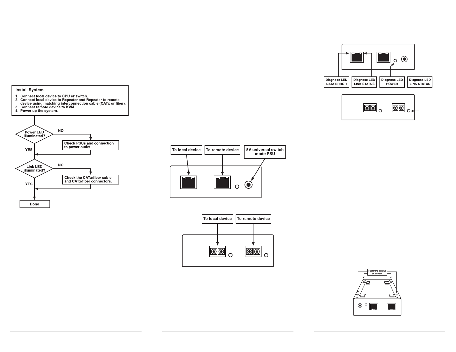
2.2 System Setup
To install your Repeater/Cross Repeater:
1. Switch off all devices.
2. Connect the interconnect cable to the local device’s
interconnect socket and the repeater/cross repeater.
3. Connect the interconnect cable to the remote device’s
interconnect socket and the repeater/cross repeater.
4. Connect the 5-VDC power supply to the repeater.
NOTE: Use only the power supply that you received with this
unit or a manufacturer-approved replacement.
3. Hardware Description
3.1 Device Views
Figure 1. Repeater/cross repeater CATx view.
Figure 2. Repeater/cross repeater fiber view.
3.2 Diagnostics
Each repeater/cross repeater has three LED indicators:
Power, Data Error, and Link Status. The Power LED is next to
the power socket.
Figure 3. Diagnostic LEDs on the repeater/
cross repeater.
Table 1. LED indicators and their functions.
LED Setting Description
Power (red) Off Device not ready
On Device ready
Link Status Blinking No interconnect
(green) connection via CATx
or fiber cable
On Device ready
Data Error (green) Not used
4. Service Setup
For most applications, you won’t need to make any
adjustments to set up your repeater/cross repeater.
For some applications, you may need to open the repeater.
Unscrew the UNC-type screws on both sides of the monitor
connections. Put the lower and upper shells of the case
aside.
Figure 4. Removing the screws.
Page 3Page 2 Page 4
724-746-5500 | blackbox.com724-746-5500 | blackbox.com 724-746-5500 | blackbox.com
 Loading...