

Page 1

November 2009
ACU2001A
ACU2009A
ACU2022A
ACU2028A
ACU2201A
ACU2222A
ACUR001A
ACUR002A
ACUR004A
ACURA001A
ACURA002A
ACURA004A
Page 2

Page 3

THE SERVSWITCH™ FAMILY
Welcome to the ServSwitch™ Family!
Thank you for purchasing a BLACK BOX® ServSwitch™ Brand CATx KVM Extender
model! We appreciate your business, and we think you’ll appreciate the many ways that your
enhanced keyboard/video/mouse system will save you money, time, and effort.
That’s because our ServSwitch family is all about breaking away from the traditional,
expensive model of computer management. You know, the one-size-fits-all-even-if-it-doesn’t
model that says, “One computer gets one user station, no more, no less.” Why not a single
user station (monitor, keyboard, and mouse) for multiple computers—even computers of
different platforms? Why not a pair of user stations, each of which can control multiple
computers? Why not multiple user stations for the same computer?
With our ServSwitch products, there’s no reason why not. We carry a broad line of robust
solutions for all these applications. Do you have just two PCs, and need an economical
alternative to keeping two monitors, keyboards, and mice on your desk? Or do you need to
share dozens of computers, including a mix of IBM® PC, RS/6000®, Apple® Macintosh®,
Sun Microsystems®, and SGI™ compatibles among multiple users with different access
levels? Does your switch have to sit solidly on a worktable and use regular everyday cables?
Or does it have to be mounted in an equipment rack and use convenient many-to-one cables?
No matter how large or small your setup is, no matter how simple or how complex, we’re
confident we have a ServSwitch system that’s just right for you.
The ServSwitch™ family from Black Box—the one-stop answer for all your KVM-switching
needs!
This manual will tell you all about your new ServSwitch™ Brand CATx KVM Extender,
including how to install, operate, and troubleshoot it. For an introduction to the Extender, see
Chapter 2. The Extender product codes covered in this manual are:
ACU2001A ACU2022A
ACU2009A ACU2028A
ACUR001A ACURA001A
ACUR002A ACURA002A
ACUR004A ACURA004A
ACU2201A** ACU2222A**
** Obsolete products. Now replaced by ACU2201A-R2 & ACU2222A-R2 and covered in a
separate User Guide.
User Guide Revision: 4.0 (November 2009)
1
Page 4

SERVSWITCH™ BRAND CATX KVM EXTENDER FAMILY
Copyrights and Trademarks
©2003/2009. All rights reserved. This information may not be reproduced in any manner
without the prior written consent of the manufacturer.
Information in this document is subject to change without notice and the manufacturer shall
not be liable for any direct, indirect, special, incidental or consequential damages in
connection with the use of this material.
All trademark and trade names mentioned in this document are acknowledged to be the
property of their respective owners.
Disclaimer
While every precaution has been taken in the preparation of this manual, the manufacturer
assumes no responsibility for errors or omissions. Neither does the manufacturer assume any
liability for damages resulting from the use of the information contained herein. The
manufacturer reserves the right to change the specifications, functions, or circuitry of the
product without notice.
The manufacturer cannot accept liability for damage due to misuse of the product or due to
any other circumstances outside the manufacturer’s control (whether environmental or
installation related). The manufacturer shall not be responsible for any loss, damage, or injury
arising directly, indirectly, or consequently from the use of this product.
Cautions and Notes
The following symbols are used in this guide:
CAUTION. This indicates an important operating instruction
that should be followed to avoid any potential damage to
hardware or property, loss of data, or personal injury.
NOTE. This indicates important information to help you make the best use of
this product.
2
Page 5

FCC/CDC STATEMENTS
FEDERAL COMMUNICATIONS COMMISSION
AND CANADIAN DEPARTMENT OF COMMUNICATIONS
RADIO-FREQUENCY INTERFERENCE STATEMENTS
This equipment generates, uses, and can radiate radio-frequency energy, and if not installed
and used properly, that is, in strict accordance with the manufacturer’s instructions, may
cause interference to radio communication. It has been tested and found to comply with the
limits for a Class A computing device in accordance with the specifications in Subpart B of
Part 15 of FCC rules, which are designed to provide reasonable protection against such
interference when the equipment is operated in a commercial environment. Operation of this
equipment in a residential area is likely to cause interference, in which case the user at his
own expense will be required to take whatever measures may be necessary to correct the
interference.
Changes or modifications not expressly approved by the party responsible for compliance
could void the user’s authority to operate the equipment.
Shielded cables must be used with this equipment to maintain compliance with radio
frequency energy emission regulations and ensure a suitably high level of immunity to
electromagnetic disturbances.
This digital apparatus does not exceed the Class A limits for radio noise emission from digital
apparatus set out in the Radio Interference Regulation of the Canadian Department of
Communications.
Le présent appareil numérique n’émet pas de bruits radioélectriques dépassant les limites
applicables aux appareils numériques de la classe A prescrites dans le Règlement sur le
brouillage radioélectrique publié par le Ministère des Communications du Canada.
3
Page 6
SERVSWITCH™ BRAND CATX KVM EXTENDER FAMILY
EUROPEAN UNION DECLARATION OF CONFORMITY
WARNING!
This is a Class A product. In a domestic environment, this product may cause
radio interference, in which case the user might be required to take adequate
remedial measures.
This product complies with the following harmonized standards for Information Technology
Equipment: EN55022:2006 (Class A), EN55024:1998 + A1:2001 + A2:2003.
To maintain compliance the use of correctly installed shielded (STP/FTP) interconnection
cable is advised. Only use CPU cables and power supplies provided (or recommended) for
use with this product.
When used in environments that have high levels of electromagnetic interference or excessive
power ground noise, you may experience disturbances to video and/or data transmission. If
this is the case, please refer to the Troubleshooting section of the User Guide for further
information, or contact Technical Support. In electrically noisy environments, the use of
shielded (STP/FTP) rather than unshielded (UTP) interconnection cable is recommended.
4
Page 7

NOM STATEMENT
NORMAS OFICIALES MEXICANAS (NOM)
ELECTRICAL SAFETY STATEMENT
INSTRUCCIONES DE SEGURIDAD
1. Todas las instrucciones de seguridad y operación deberán ser leídas antes de que el
aparato eléctrico sea operado.
2. Las instrucciones de seguridad y operación deberán ser guardadas para referencia futura.
3. Todas las advertencias en el aparato eléctrico y en sus instrucciones de operación deben
ser respetadas.
4. Todas las instrucciones de operación y uso deben ser seguidas.
5. El aparato eléctrico no deberá ser usado cerca del agua—por ejemplo, cerca de la tina de
baño, lavabo, sótano mojado o cerca de una alberca, etc..
6. El aparato eléctrico debe ser usado únicamente con carritos o pedestals que sean
recomendados por el fabricante.
7. El aparato eléctrico debe ser montado a la pared o al techo sólo como sea recomendado
por el fabricante.
8. Servicio—El usuario no debe intentar dar servicio al equipo eléctrico más allá a lo
descrito en las instrucciones de operación. Todo otro servicio deberá ser referido a
personal de servicio calificado.
9. El aparato eléctrico debe ser situado de tal manera que su posición no interfiera su uso.
La colocación del aparato eléctrico sobre una cama, sofá, alfombra o superficie similar
puede bloquea la ventilación, no se debe colocar en libreros o gabinetes que impidan el
flujo de aire por los orificios de ventilación.
10. El equipo eléctrico deber ser situado fuera del alcance de fuentes de calor como
radiadores, registros de calor, estufas u otros aparatos (incluyendo amplificadores) que
producen calor.
11. El aparato eléctrico deberá ser connectado a una fuente de poder sólo del tipo descrito en
el instructivo de operación, o como se indique en el aparato.
12. Precaución debe ser tomada de tal manera que la tierra fisica y la polarización del equipo
no sea eliminada.
13. Los cables de la fuente de poder deben ser guiados de tal manera que no sean pisados ni
pellizcados por objetos colocados sobre o contra ellos, poniendo particular atención a los
contactos y receptáculos donde salen del aparato.
5
Page 8

SERVSWITCH™ BRAND CATX KVM EXTENDER FAMILY
14. El equipo eléctrico debe ser limpiado únicamente de acuerdo a las recomendaciones del
fabricante.
15. En caso de existir, una antena externa deberá ser localizada lejos de las lineas de energia.
16. El cable de corriente deberá ser desconectado del cuando el equipo no sea usado por un
largo periodo de tiempo.
17. Cuidado debe ser tomado de tal manera que objectos liquidos no sean derramados sobre
la cubierta u orificios de ventilación.
18. Servicio por personal calificado deberá ser provisto cuando:
A: El cable de poder o el contacto ha sido dañado; u
B: Objectos han caído o líquido ha sido derramado dentro del aparato; o
C: El aparato ha sido expuesto a la lluvia; o
D: El aparato parece no operar normalmente o muestra un cambio en su desempeño; o
E: El aparato ha sido tirado o su cubierta ha sido dañada.
6
Page 9

SAFETY PRECAUTIONS AND INSTALLATION GUIDELINES
Safety Precautions and Installation Guidelines
To ensure reliable and safe long-term operation please note the following installation
guidelines:
• Do not use to link between buildings.
• Only use in dry, indoor environments.
• If the building has 3-phase AC power, try to ensure that equipment connected to the
Local and Remote Units is on the same phase.
• Try not to route the CATx link cable alongside power cables.
• The use of shielded CATx cable is recommended to maintain compliance.
• Ensure that the system connected to the Local Unit is connected to power ground.
• Ensure that the monitor connected to the Remote Unit is connected to power ground and
does not use an isolated power supply.
• The Remote Unit and any power supplies can get warm. Do not situate them in an
enclosed space without any airflow. Do not place the power supply directly on top of the
Remote Unit. Do not obscure the Remote Unit’s ventilation holes.
• This product is not suitable for use in isolated medical environments.
To safeguard against personal injury and avoid possible
damage to equipment or property, please observe the
following:
• Only use power supplies originally supplied with the
product or manufacturer-approved replacements. Do not
attempt to dismantle or repair any power supply. Do not
use a power supply if it appears to be defective or has a
damaged case.
• Connect all power supplies to grounded outlets. In each
case, ensure that the ground connection is maintained
from the outlet socket through to the power supply’s AC
power input.
• Do not attempt to modify or repair this product, or make
a connection from the CATx link interface (RJ45) to any
other products, especially telecommunications or
network equipment.
7
Page 10

SERVSWITCH™ BRAND CATX KVM EXTENDER FAMILY
Contents
1. Quick Setup 10
1.1 Command Summary 11
2. Overview 12
2.1 Introduction 12
2.2 Glossary 12
2.3 Features 14
2.4 Product Range 15
2.5 Compatibility 16
2.6 How to Use This Guide 17
3. Installation 18
3.1 Package Contents 18
3.2 Interconnection Cable Requirements 19
3.3 Remote Unit Installation 20
3.4 Local Unit Installation 23
3.5 Connection to Rack Mount Hub Local Units 26
4. Remote Unit Configuration & Operation 29
4.1 Video Configuration Overview 29
4.2 Video Adjustments 30
4.3 Command Mode 31
4.4 Adjusting Video 32
4.5 Other Remote Configuration & Operation Options 37
5. Local Unit Operation 40
5.1 Overview 40
5.2 Dual Access Systems 41
6. Troubleshooting 43
6.1 Video 43
6.2 Keyboard & Mouse 45
6.3 Audio 46
6.4 Serial 46
6.5 General Questions 47
8
Page 11

CONTENTS
Appendix A: Example Applications 48
Appendix B: Rack Mount Options 53
Appendix C: Remote Unit: Flash Upgrading &
External Configuration 55
Appendix D: Advanced Cabling Issues (Skew) 56
Appendix E: Audio/Serial Ports 59
Appendix F: Calling Black Box 61
Appendix G: Specifications 62
9
Page 12
SERVSWITCH™ BRAND CATX KVM EXTENDER FAMILY
V
/
g
1. Quick Setup
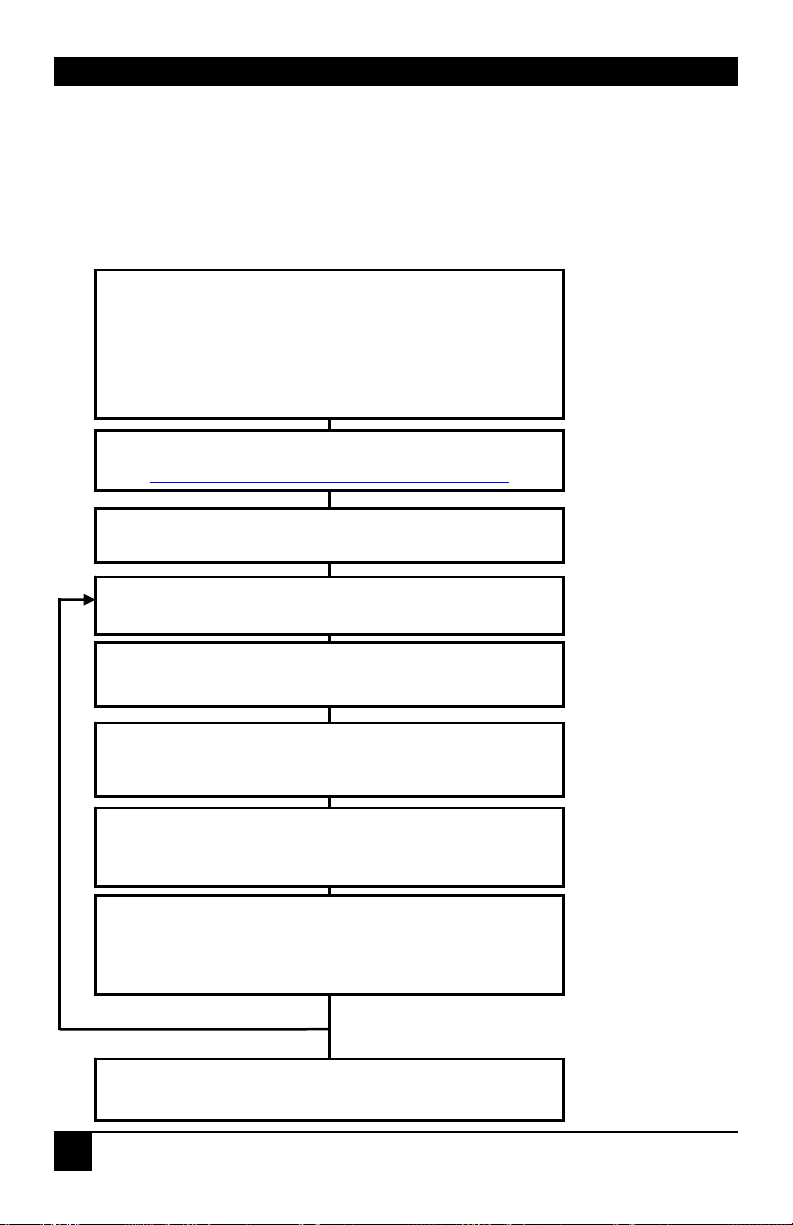
This section briefly describes how to install your KVM extender system and optimize the
video signals. Unless you are an experienced user, we recommend that you follow the full
procedures described in the rest of this manual. Refer to the command summary on the next
page when following this procedure.
Install system
.
1. Connect Remote Unit to KVM and audio/serial devices
(if present).
2. Connect Local Unit or Extender hub to CPU.
3. Connect Remote and Local Units with compatible CATx
Interconnect cable.
4. Power up system.
iew Test Card
ftp://ftp.blackbox.com/connectivity/ServSwitch
Enter Command Mode on Remote Unit
<Left Control> + <Left Shift> + <F10>
Choose video channel
Reset channel
Apply Assisted EQ
Next: <Left Control> + <Page Up>
Previous: <Left Control> + <Pa
Correct Skew
Adjust the individual color delays until the test card’s RGB
vertical lines are aligned.
<1>, <2>, <3>, <4> or <0> (all)
<Left Control> + <Home>
Fine tune LF and HF EQ
Reduce smearing and loss of sharpness.
TFT Users: Set to auto-adjust, or if you are an advanced
user, manually adjust the monitor’s clock and phase.
Yes
More channels?
No
Exit Command Mode
<ESC>
e Down>
Any Problems? See
Installation and
Troubleshooting
sections.
Provides useful
image for adjusting
video.
All adjustments apply
to selected channel.
See page 33.
Obtain approx. EQ
setting. See page 33.
See page 34 and, for
a detailed discussion
of skew correction,
see Appendix D.
Optimize video quality.
See page 36.
10
Page 13

QUICK SETUP
1.1 Command Summary
The following table summarizes the ‘hot’ key command sequences used in system
configuration and video tuning on a Remote Unit console.
Command Mode
Enter Command Mode
Exit Command Mode & Save
Exit Command Mode Without Save
Video Channel Selection
Select Channel For Adjustment
Select ALL Video Channels
Assisted EQ
Next Assisted EQ Setting
Previous Assisted EQ Setting
Reset EQ & Delay Values
Reset EQ Values
LF/HF Equalization
Increase LF Equalization (Coarse)
Increase LF Equalization (Fine)
Decrease LF Equalization (Coarse)
Decrease LF Equalization (Fine)
Increase HF Equalization (Coarse)
Increase HF Equalization (Fine)
Decrease HF Equalization (Coarse)
Decrease HF Equalization (Fine)
Quick Skew
Toggle RED Delay (19nS)
Toggle GREEN Delay (19nS)
Toggle BLUE Delay (19nS)
Delay (Skew)
Increase RED Delay
Increase GREEN Delay
Increase BLUE Delay
Decrease RED Delay
Decrease GREEN Delay
Decrease BLUE Delay
Reset Commands
Reset Mouse and Keyboard
Mouse Recovery
Set Extender To Default State
Other Commands
Toggle Remote Unit Private Mode
Toggle Local Unit Initial Hot Key
Local Unit Scroll Lock Key Mode
<Left Control> + <Left Shift> + <F10>
<ESC>
<Left Control> + <ESC>
<1>, <2>, <3>, <4>
<0>
<Left Control> + <Page Up>
<Left Control> + <Page Down>
<Left Control> + <Home>
<Left Control> + <End>
<L> + <Up Arrow>
<L> + <Right Arrow>
<L> + <Down Arrow>
<L> + <Left Arrow>
<H> + <Up Arrow>
<H> + <Right Arrow>
<H> + <Down Arrow>
<H> + <Left Arrow>
<Left Control> + <R>
<Left Control> + <G>
<Left Control> + <B>
<R> + <Right Arrow>
<G> + <Right Arrow>
<B> + <Right Arrow>
<R> + <Left Arrow>
<G> + <Left Arrow>
<B> + <Left Arrow>
<F1>
<F3>
<Left Control> + <F9>
<Scroll Lock>
<F7>
<F5>
11
Page 14

SERVSWITCH™ BRAND CATX KVM EXTENDER FAMILY
2. Overview
2.1 Introduction
The ServSwitch™ Brand CATx KVM Extender Series enables high-resolution video, PS/2
keyboard and mouse, stereo audio, and serial port signals to be communicated up to 1000ft
(300m) over Category 5, 5e, 6 or higher (CATx) cable.
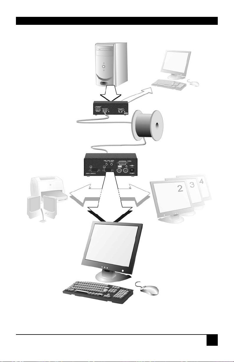
A basic KVM extension system comprises a Local Unit (transmitter) and a Remote Unit
(receiver). The Local Unit connects directly to the computer (or a KVM switch system) using
the supplied cable(s). The user console (keyboard, mouse and monitor) attaches to the
Remote Unit. The Remote and Local Units communicate video and data information along
the connecting CATx cable (see Figure 1).
Within the product range, models are available with combinations of the following:
• Audio transmission: bi-directional stereo audio (16-bit digitized).
• Serial transmission: transparent serial COM port (to 19.2Kbps).
• Dual access: allowing a second user console at the Local Unit.
• Multiple video channels: single, dual and quad video heads.
2.2 Glossary
The following terms are used in this guide:
CATx
PSU
KVM
Console
Dual Access
Single Head
Dual Head
Quad Head
Any Category 5, 5e, 6 or higher cable.
Power Supply Unit.
Keyboard, Video and Mouse.
A keyboard, monitor, and mouse, plus optional serial/audio
devices.
A system allowing connection of local and remote user consoles.
An extender system that supports one monitor.
An extender system that supports two monitors.
An extender system that supports four monitors.
12
Page 15
OVERVIEW
LOCAL Unit
KVM extension over CATx
cables up to 1000ft (300m).
REMOTE Unit
Serial and Audio
Transmission
ACU2022A, ACU2028A
ACU2222A, ACURA001A
ACURA002A, ACURA004A
only
Local Access
ACU2009A, ACU2028A only.
Dual Video Support
ACU2201A, ACU2222A
ACUR002A, ACURA002A
only
Quad Video Support
ACUR004A, ACURA004A
only
Figure 1 KVM extender system
13
Page 16

SERVSWITCH™ BRAND CATX KVM EXTENDER FAMILY
2.3 Features
All members of the ServSwitch™ Brand CATx KVM Extender Series offer the following
features:
• Support for high video resolution over extended distances:
1600x1200@60Hz over 650ft (200m)
1280x1024@75Hz over 1000ft (300m)
Higher resolutions may be possible over shorter distances.
• Fully integrated skew compensation allows operation with CATx cables by canceling
color shift and enhancing sharpness.
• Independent low frequency (LF) and high frequency (HF) cable equalization control
ensures optimum video tuning across different cable types.
• Models available with single, dual and quad-head video support (one CATx cable
required for each video channel).
• All control and video tuning carried out using the remote keyboard with settings stored
in EEPROM memory.
• Remote Unit firmware and settings flash upgradeable.
• Intelligent PS/2 keyboard and mouse emulation ensures PCs do not lock-up and allows
peripherals to be hot-plugged.
• Dual access models allow local or remote operation.
• DDC emulation in Local Unit ensures compatibility for all standard graphics modes.
• Transparent serial port (on certain models) enables any serial device to be extended (up
to 19.2K Baud). The serial port may be used to extend one device (requiring
handshaking lines), or up to three simple serial devices (no handshaking).
• Bi-directional stereo audio (16-bit digitized) support on certain models enables high-
quality audio extension.
• Local Units are normally powered directly by the PC (or switch).
• Private Mode on dual access models allows user to lock out other console.
• Status indicator LEDs on each RJ45 port.
• Small footprint chassis with rack mount options available.
• Surge protection on each RJ45 port.
• Remote Units are fully compatible with ServSwitch™ CAT5 KVM Extender Local Units
and hubs.
• CPU cables included (certain models).
14
Page 17
OVERVIEW
2.4 Product Range
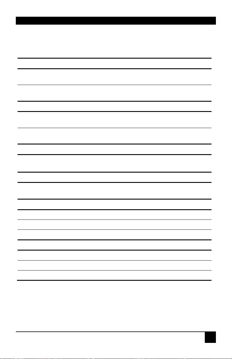
There are twelve products in the range:
Single Video Channel Kits (Standard)
ACU2001A Single Video Channel, PS/2 KB & Mouse
Local Unit (Single Access) + Remote Unit
ACU2009A Single Video Channel, PS/2 KB & Mouse
Local Unit (Dual Access) + Remote Unit
Single Video Channel Kits (Audio)
ACU2022A Single Video Channel, PS/2, Serial, Stereo Audio
Local Unit (Single Access) + Remote Unit
ACU2028A Single Video Channel, PS/2, Serial, Stereo Audio
Local Unit (Dual Access) + Remote Unit
Dual Video Channel Kit (Standard)
ACU2201A** Dual Video Channels, PS/2 KB & Mouse
Local Unit + Remote Unit (Dual Video)
Dual Video Channel Kit (Audio)
ACU2222A** Dual Video Channels, PS/2, Serial, Stereo Audio
Local Unit + Remote Unit (Dual Video)
Remote Units With PS/2 Interfaces
ACUR001A Single Video Channel, PS/2 KB & Mouse
ACUR002A Dual Video Channels, PS/2 KB & Mouse
ACUR004A Quad Video Channels, PS/2 KB & Mouse
Remote Units With PS/2, Serial and Audio Interfaces
ACURA001A Single Video Channel, PS/2, Serial, Stereo Audio
ACURA002A Dual Video Channels, PS/2, Serial, Stereo Audio
ACURA004A Quad Video Channels, PS/2, Serial, Stereo Audio
** Obsolete products. Now replaced by ACU2201A-R2 & ACU2222A-R2 and covered in a
separate User Guide.
15
Page 18
SERVSWITCH™ BRAND CATX KVM EXTENDER FAMILY
2.5 Compatibility
Interface Compatibility
• PS/2 Keyboard: Compatible with all standard keyboards. Certain keyboards with
enhanced features may also be supported with custom firmware.
• PS/2 Mouse: Compatible with all standard 2-button, 3-button and wheel mice. To
connect to a PC which does not have a PS/2 mouse port, an active serial converter is
required – Model No: AC244A.
• Audio: Input and output are line-level. Amplified speakers are required. A microphone
may be directly connected to the Remote Unit (optional pre-amplification).
• Serial: Transparent up to 19.2K Baud (38.4K operation may be possible with some
devices). The following serial signals are extended: TX, RX, RTS, CTS, DTR, DSR. In
rare cases, a wiring adaptor may be required to transfer RI and DCD.
• Video: VGA to UXGA. Separate sync, composite sync, or sync-on-green. Maximum
resolution and refresh rates depend on cable length and cable type (see Appendix G:
Specifications, page 62).
Extender Compatibility
The ServSwitch™ Brand CATx KVM Extender Series of CATx KVM extender products
offer enhanced performance while maintaining complete compatibility with existing
ServSwitch™ standalone and rack mount CAT5 extenders.
You can use CAT5 and CATx products belonging to the same family in any combination.
However, it is not possible to mix Standard and Audio products within a system. CATx units
are not currently compatible with SUN (ACU1004A, ACU1005A) or Serial-only products
(ACU1002A, ACU1008A, ACUSREM, ACU1006SRA, ACU1006DSRA).
Standard Family Audio Family
Standard family units are compatible
with the following CAT5 products:
ACU1001A ACU1009A ACU1022A ACU1028A
ACU3001A ACU3009A ACU3022A ACUVREM
ACU1049A ACUMREM ACUWREM ACU1006VRA
ACUREM ACUREMSW ACU1006DVRA ACU1006MRVA
ACU1006RA ACU1006DRA
ACU1012RA ACU1006MRA
Audio family units are compatible with the
following CAT5 products:
16
Page 19

OVERVIEW
2.6 How to Use This Guide
This guide describes the installation and configuration of the ServSwitch™ Brand CATx
KVM Extender Series. Although the connection and operation of the system is relatively
straightforward, you should consider the following before getting started:
Connection & Compatibility
If you have purchased an Extender Kit, this will contain all the cables required to connect the
Local Unit to your PC or KVM switch. The remote console (keyboard, monitor and mouse)
and any audio and serial equipment connects directly to the Remote Unit.
If you have purchased a Remote Unit, ensure that it is compatible with your Local Unit (see
Compatibility, page 16).
For information about connection and installation, see Installation, page 18.
Interconnection Cable
You will need CATx (any category 5, 5e, 6 or higher) cable, terminated with RJ45 plugs, to
connect the Local and Remote Units (see Interconnection Cable Requirements, page 19.
Adjusting Video
Video signals become distorted when transmitted over CATx cables. To get the best from
your extender system, it is essential that you adjust the Remote Unit to optimize the video
image quality:
• For experienced users, there is a Quick Setup section at the start of this guide (see page
10).
• For the full procedure, see Remote Unit Configuration & Operation, page 29.
• Refer to Appendix D: Advanced Cabling Issues (Skew), page 56 for a more in depth
discussion of skew correction and advanced cabling issues.
17
Page 20

SERVSWITCH™ BRAND CATX KVM EXTENDER FAMILY
3. Installation
For first-time users, we recommend that you carry out a test placement, confined to a single
room, before commencing full installation. This will allow you to identify and solve any
cabling problems, and experiment with the KVM extender system more conveniently.
3.1 Package Contents
You should receive the following items in your extender package. If anything is missing,
please refer to Appendix F to obtain Technical Support.
• Extender Remote Unit.
• 9V DC universal power supply for Remote Unit.
• Extender Local Unit.
Only included in extender kits.
• 6ft (1.8m) KVM CPU combination cable with PS/2 (6-pin mini-DIN male-to-male)
keyboard and mouse connectors and VGA video (HD15 male to female) connector.
Models: ACU2001A, ACU2009A, ACU2022A and ACU2028A only.
• 3ft (1.0m) KVM CPU combination cable with PS/2 (6-pin mini-DIN male-to-male)
keyboard and mouse connectors, VGA video (HD15 male) connector, and 25-way
(DB25 Female) extender connector.
Models: ACU2201A and ACU2222A only.
• 3ft (1.0m) CPU video cable with VGA video (HD15 male) connector and a 25-way
(DB25 Female) extender connector.
Models: ACU2201A and ACU2222A only.
• 6ft (1.8m) Serial cable (DB9 male/female connectors, 1:1 connections).
Models: ACU2022A, ACU2028A and ACU2222A only.
• 6ft (1.8m) Dual audio cable (3.5mm stereo plugs).
Models: ACU2022A, ACU2028A and ACU2222A only.
• IEC AC Power Cord.
• Quick Start Guide.
18
Page 21

INSTALLATION
3.2 Interconnection Cable Requirements
To connect the Local and Remote Units you will need CATx (any category 5, 5e, 6 or higher)
cable terminated with RJ45 plugs. Please note that shielded cable is advised to maintain
regulatory EMC compliance.
Interconnect cables must be solid-core type. Stranded patch cable will give poor results over
longer distances. The pairing of the cable and pinning of its connectors should normally be in
accordance with EIA-568B (see page 57).
One CATx cable is required for each video channel.
• The Primary interconnect cable connects INTERCONNECT Port 1 on the Local and
Remote Units. This carries the main video channel and all data (plus audio/serial).
• Secondary CATx cables (connected to INTERCONNECT Ports 2 - 4) carry additional
video channels on multi-head units.
In order to send Keyboard, Mouse, Audio and Serial signals to the PC, the
Primary interconnect must be connected.
The Primary interconnect does not have to be connected in order to use the
keyboard attached to the Remote Unit for setup. However, if the Primary
interconnect is disconnected, the keyboard cannot be used for configu ration for 15
seconds after disconnection (to maintain data integrity).
With some cables, video performance may be improved by using a crossover patch
cable at each end or an alternative RJ45 pin-out (see Appendix D: Advanced Cabling
Issues (Skew), page 56).
19
Page 22

SERVSWITCH™ BRAND CATX KVM EXTENDER FAMILY
3.3 Remote Unit Installation
To install a Remote Unit:
1. Switch off all devices.
2. Connect your keyboard, monitor(s) and mouse to the Remote Unit as shown in
Figure 2 (single and dual head units) or Figure 4 (quad head units).
These ports may also be attached to the CPU side of a KVM switch in
order to have a remote CPU. However, if you are attempting to use the
extender between cascaded KVM switches this may not work. Please contact
Technical Support to discuss your applicati o n.
3. If appropriate, connect audio equipment and serial devices. Connect the audio cables as
follows:
Remote Unit Audio Device
Audio Out Speakers
Audio In (MIC) Microphone
See Appendix E: Audio/Serial Ports, page 59 for further information.
4. Connect the Primary CATx cable to the INTERCONNECT (1) socket on the front of the
Remote Unit. For dual and quad systems, connect additional CATx cables as required
(see Figure 3 and Figure 5).
5. Connect the 9V power supply to power the unit.
Only use the power supply originally supplied with this
equipment or a manufacturer approved replacement.
NEVER CONNECT THE REMOTE UNIT 9V POWER SUPPLY TO A
LOCAL UNIT: YOU WILL DAMAGE THE EXTENDER SYSTEM.
Choose a well-ventilated location for a quad head unit. When in
use, these can generate a considerable amount of heat.
20
Page 23
INSTALLATION
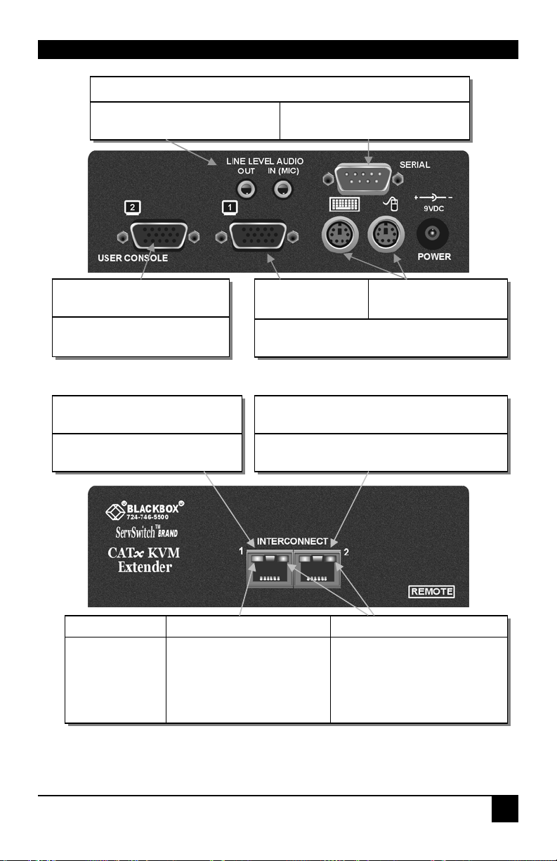
Figure 2 Single/Dual Head Remote Unit – rear view
ACURA001A, ACURA002A, ACU2022A, ACU2028A, ACU2222A only
Connect to speakers and
microphone.
Connect to second monitor.
ACUR002A, ACURA002A,
ACU2201A, ACU2222A only
All Remote Units
INTERCONNECT 1 – carries
primary video and data signals.
Connect to serial device, such as
a touch screen.
Connect to
Primary monitor.
All Remote Units
ACU2201A, ACU2222A,
ACUR002A, ACURA002A only
INTERCONNECT 2 – carries secondary video
signals.
Connect PS/2
keyboard and mouse.
Status Yellow LED* Green LED
OFF
ON
FLASHING
* Yellow LED active on primary INTERCONNECT socket (Channel 1) only
No data transfer with Local
Unit
Remote Unit in Command
Mode
Data transfer with Local Unit
Remote Unit not powered.
Remote Unit powered but no
video found
Remote Unit powered & video
sync found
Figure 3 Single/Dual Head Remote Unit - front view
21
Page 24
SERVSWITCH™ BRAND CATX KVM EXTENDER FAMILY
Connect to serial device,
for example, a touch screen.
Connect to third
and fourth
monitors.
Connect to
second
monitor.
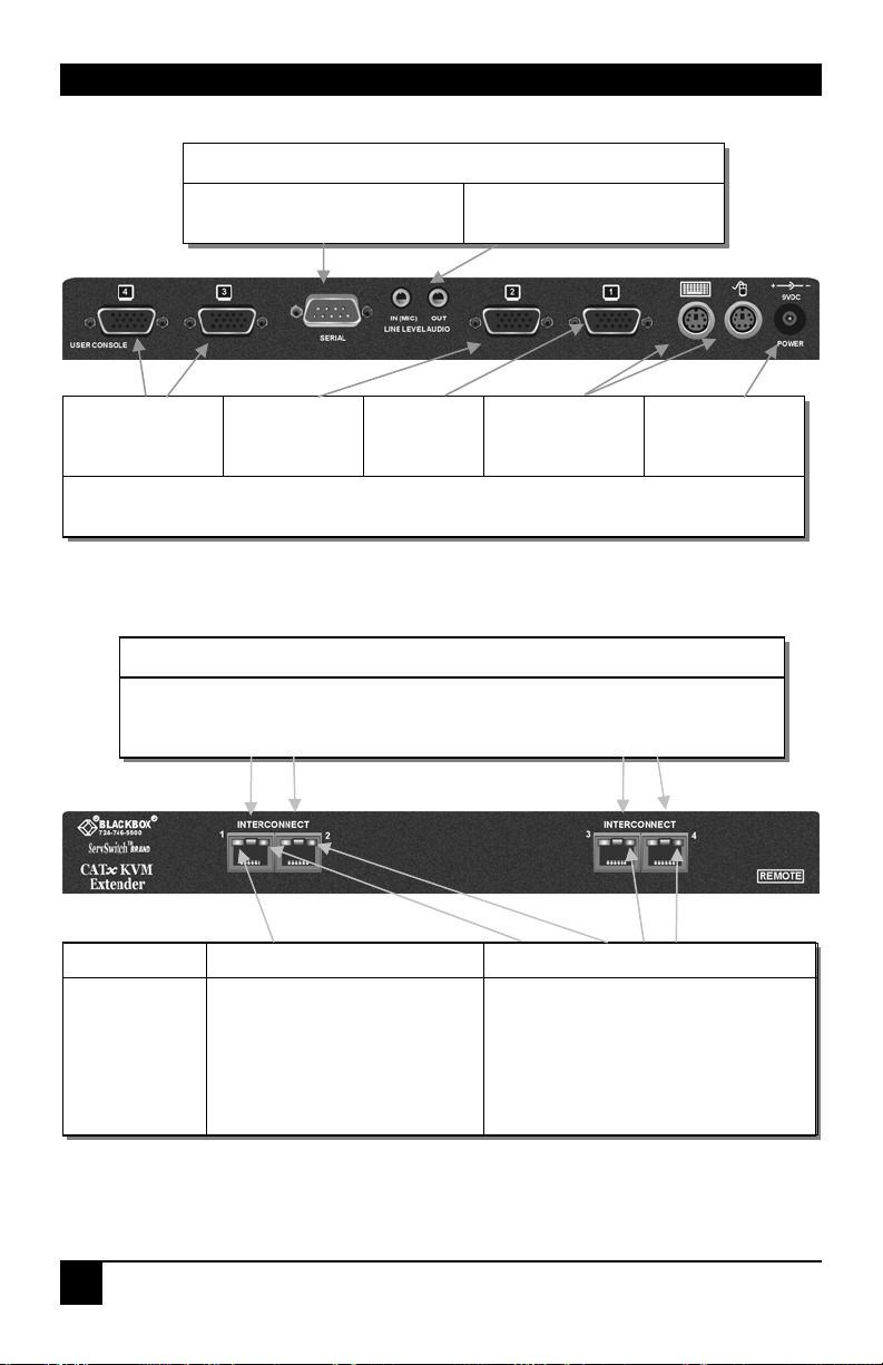
Figure 4 Quad Head Remote Unit – rear view
INTERCONNECT 1 – carries primary video and data signals. Connect to
INTERCONNECT Port 1 on Local Unit using CATx cable.
INTERCONNECT 2,3 and 4 – carry additional video signals.
ACURA004A only
Connect to speakers and
microphone.
Connect to
primary
monitor.
ACUR004A and ACURA004A
ACUR004A and ACURA004A
Connect PS/2
keyboard and
mouse.
Connect
approved 9V
power supply.
Status Yellow LED* Green LED
OFF
ON
FLASHING
* Yellow LED active on primary INTERCONNECT socket (Channel 1) only
No data transfer with Local Unit
Remote Unit in Command
Mode
Data transfer with Local Unit
Remote Unit not powered.
Remote Unit powered but no video
found
Remote Unit powered & video sync
found
Figure 5 Quad Head Remote Unit – front view
22
Page 25

INSTALLATION
3.4 Local Unit Installation
To install a Local Unit:
1. It is recommended that the PC and other devices are switched off before connection.
2. Using the supplied CPU KVM cable(s), connect the keyboard, monitor(s) and mouse
connectors on the computer (or KVM switch) to the corresponding connectors on the
Local Unit as shown in Figure 6 for single video units, or Figure 7 for dual video units.
Ensure that you attach the keyboard and mouse connectors to the correct ports. The
keyboard connector is purple; the mouse connector is green.
If your PC does not have a PS/2 mouse port, an active serial converter
will be required - Model No: AC244A.
3. If you have a dual access system, connect the keyboard, mouse and monitor for the local
console to the appropriate ports on the Local Unit. The ports may also be used to feed
into a KVM switch.
4. If you have an audio and serial enabled system, connect the audio cables between the
computer and Local Unit as follows:
Computer Local Unit
Audio Out (green) Audio In
Audio In/Microphone (pink/blue) Audio Out
5. If appropriate, connect the supplied serial cable between the serial port on the computer
and the Local Unit.
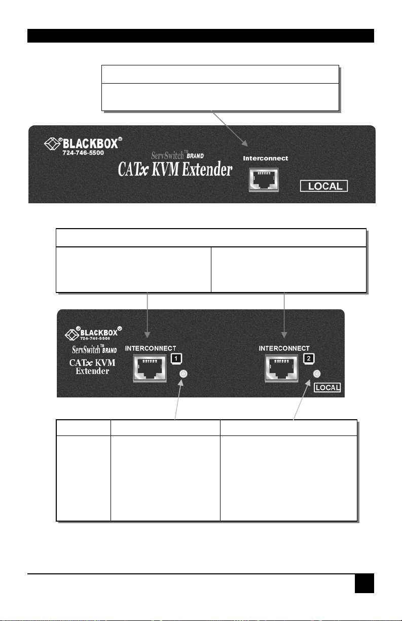
6. For single video units, connect the CATx cable to the INTERCONNECT socket on the
front of the Local Unit (see Figure 8). For dual-head systems, connect the CATx cables
from the Remote Unit to the corresponding INTERCONNECT ports (1&2) on the Local
Unit (see Figure 9).
7. Power up the PC.
The Local Unit normally takes power through the PC keyboard port. In
video only applications, this connection is not used and so an external
PSU is required.
Models ACU2201A and ACU2222A have a port for an optional 5V p owe r
supply (PSU1006E-R3). Models ACU2001A, ACU2009A, ACU2022A, and
ACU2028A require a 5V PSU with a MiniDIN connector to be plugged into the
extender’s keyboard port.
Please contact Technical Support to obtain a suitable power supply.
NEVER CONNECT THE REMOTE UNIT 9V POWER SUPPLY
TO A LOCAL UNIT: YOU WILL DAMAGE THE EXTENDER
SYSTEM.
23
Page 26
SERVSWITCH™ BRAND CATX KVM EXTENDER FAMILY
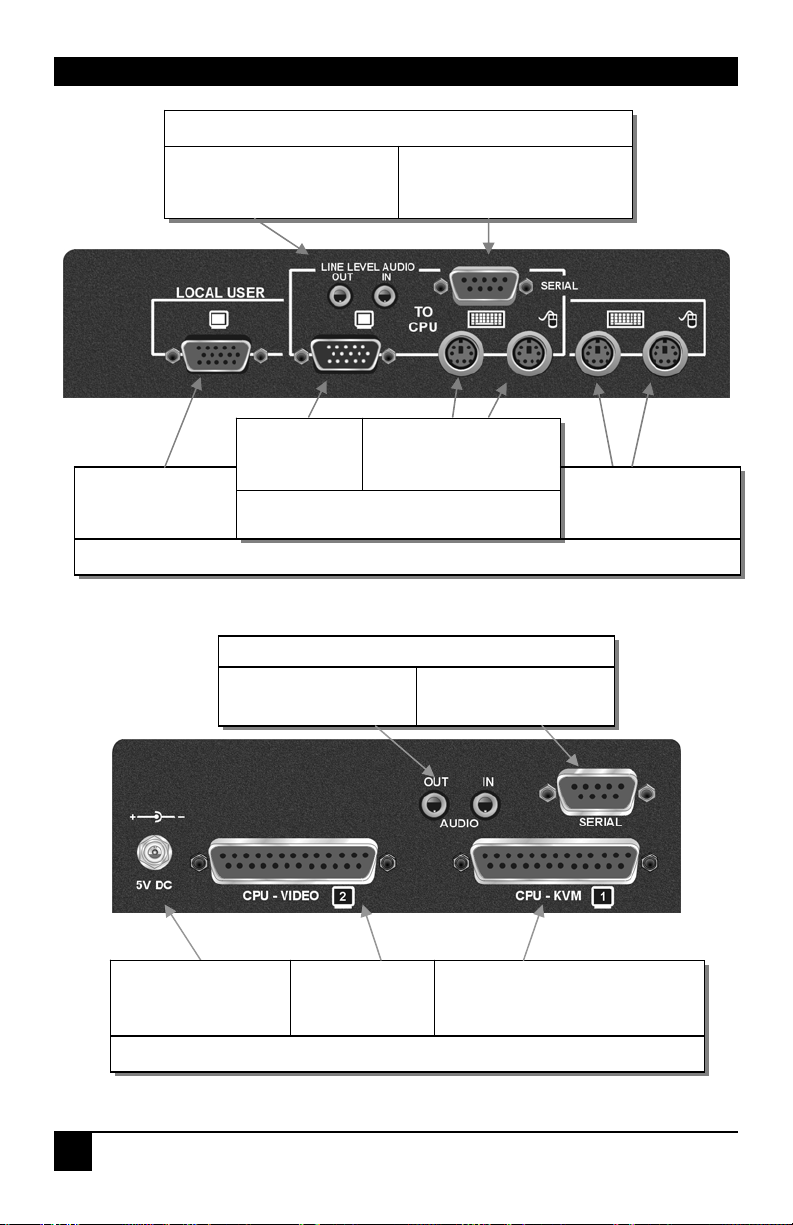
Connect to audio ports on
computer.
Connect to Local
monitor.
ACU2009A, ACU2028A only
Figure 6 Local Unit (Single Video) - rear view
ACU2028A and ACU2022A only
Connect to serial port on
computer.
Connect to
computer’s
video output.
ACU2001A, ACU2022A,
ACU2009A, ACU2028A
Connect to audio ports
on computer.
Connect to computer’s
PS/2 keyboard and
mouse ports.
ACU2222A only
Connect to Local
PS/2 keyboard and
mouse.
Connect to serial port
on computer.
Optional connection
for 5V PSU (not
supplied)
Connect to
secondary
video output.
Connect to computer’s primary
video, PS/2 keyboard and mouse
ports using supplied cable.
ACU2201A and ACU2222A
Figure 7 Local Unit (Dual Video) - rear view
24
Page 27
INSTALLATION
Figure 8 Local Unit (Single Video) – front view
INTERCONNECT 1 – carries primary
video and data signals. Connect to
CATx cable from INTERCONNECT 1
port on Remote Unit.
ACU2001A, ACU2022A, ACU2009A, ACU2028A only
INTERCONNECT – carries video and data signals. Connect
to CATx cable from INTERCONNECT port on Remote Unit.
ACU2201A and ACU2222A only
INTERCONNECT 2 – carries
secondary video signals. Connect to
CATx cable from INTERCONNECT 2
port on Remote Unit.
OFF
ON
FLASHING
Status LED Power LED*
No power - Local Unit not
connected or defective
No link to Remote Unit
Link operating correctly
No power
Power on
*If LED is dim you need to use
an external PSU
Figure 9 Local Unit (Dual Video) – front view
25
Page 28

SERVSWITCH™ BRAND CATX KVM EXTENDER FAMILY
3.5 Connection to Rack Mount Hub Local Units
Remote Units are compatible with CAT5 KVM Extender Local Hubs belonging to the same
family:
Remote Units Compatible Local Rack Hubs
ACUR001A, ACUR002A,
ACUR004A
ACURA001A, ACURA002A,
ACURA004A
You can use Rack Extender Hubs in a number of ways:
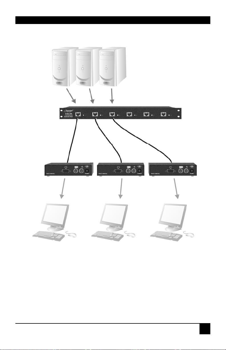
• Individually, connecting a single-head Remote Unit to each port (see Figure 10)
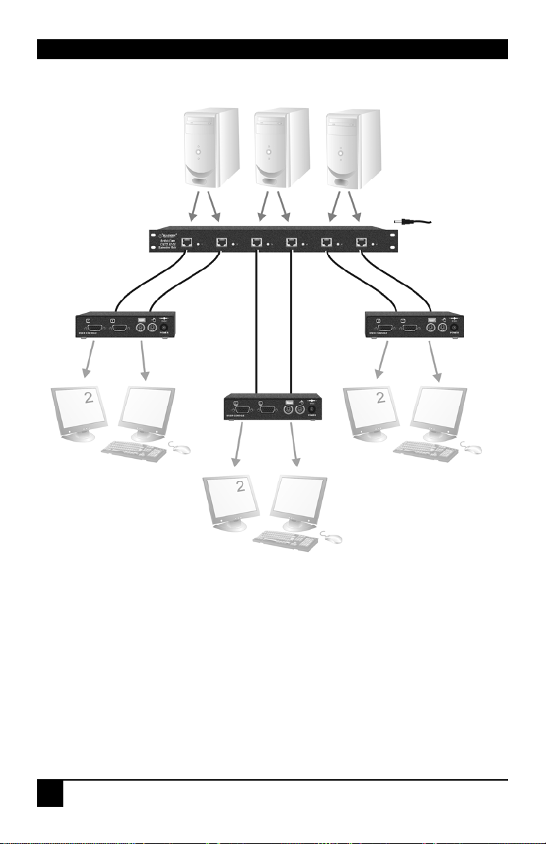
• With multi-head Remote Units, using adjacent hub ports to transmit the primary
video/data and secondary video signals (see Figure 11).
For more complex examples showing the use of Rack Extender Hubs with Remote Units in
efficient ways, see Appendix A: Example Applications, page 48. Additional video channels
do not require the Extender Hub to be of the same family. For example, an ACU1012RA
could be efficiently used to transmit multiple secondary video channels to ACURA002A
units.
ACU1006RA, ACU1006DRA, ACU1012RA
ACU1006VRA, ACU1006DVRA
Individual Rack Hub operation is not covered in this guide. Please refer to
the documentation supplied with your Rack Hub unit.
26
Page 29
INSTALLATION
Figure 10 Simple system using ACU1006RA hub and ACUR001A
Remote Units
27
Page 30
SERVSWITCH™ BRAND CATX KVM EXTENDER FAMILY
5V PSU
Figure 11 ACU1006RA rack used with ACUR002A Units to extend
dual video
28
Page 31
REMOTE UNIT CONFIGURATION & OPERATION
4. Remote Unit Configuration &
Operation
Cat5/5e/6 cables are specifically designed for networking applications and not for
transmitting analog video. Your CATx KVM extender includes, and requires, advanced
technology to enable its use at high screen resolutions. This section describes how to optimize
the video signal, configure the Extender system and operate the Remote Unit.
For details about flash upgrading and external configuration see Appendix C: Remote Unit:
Flash Upgrading & External Configuration, page 55.
For more information about serial/audio port operation, see Appendix E: Audio/Serial
Ports, page 59.
4.1 Video Configuration Overview
To get the best out of your extender system it is essential that you configure it correctly and
tune the video signal. Tuning is necessary because of distortions that occur in a video signal
when it is transmitted over lengthy CATx cables. Generally, you only need to carry out this
procedure after installation. The system stores settings in an EEPROM in the Remote Unit
and restores them whenever the unit is powered up.
When you have installed your extender system, run an application that requires a high screen
resolution. Examine the video image on the remote console’s monitor. You may see some of
the following distortion effects:
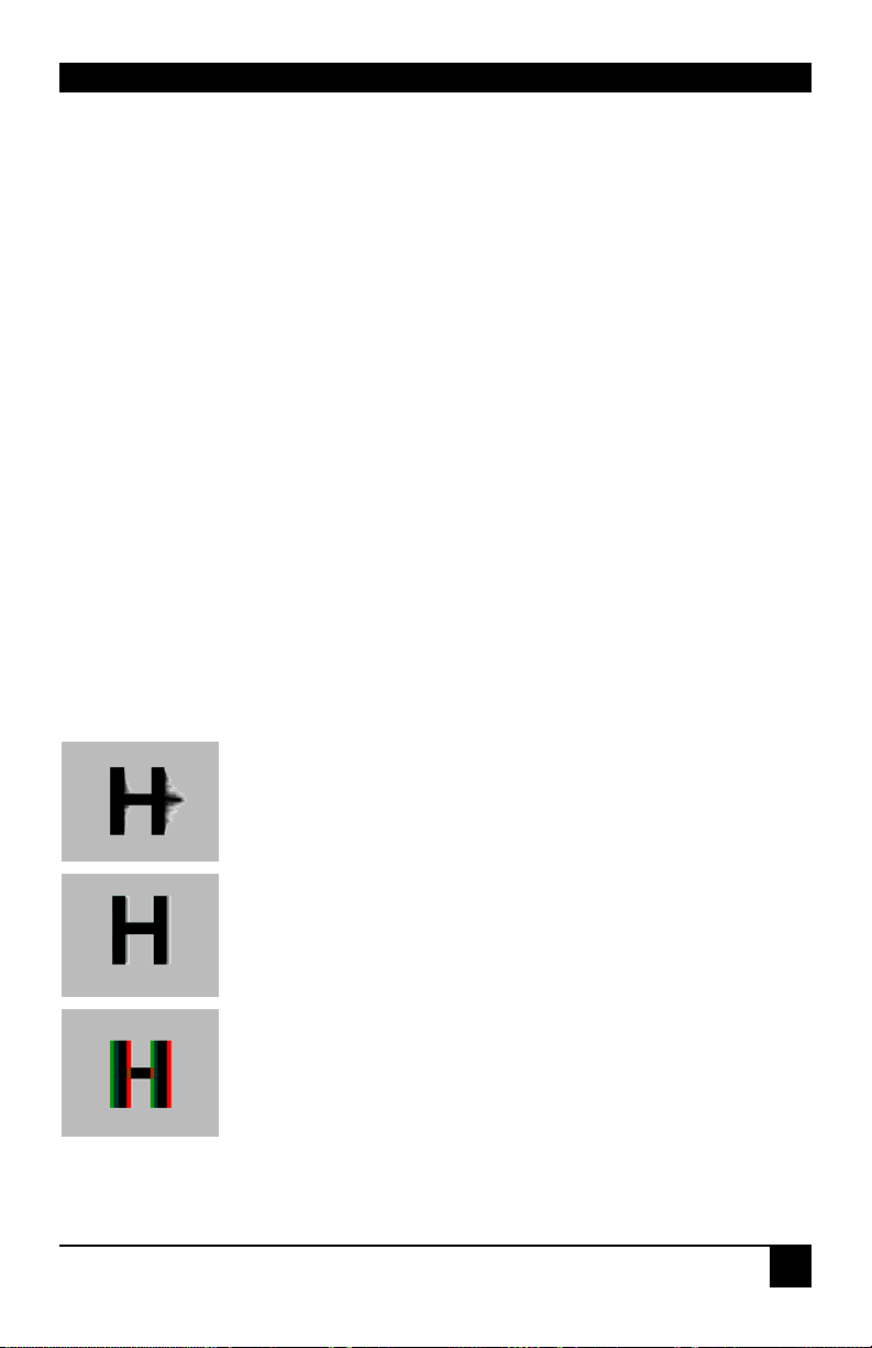
Smearing: black smearing at the right-hand edge of large horizontal
objects such as title bars and characters. To correct this smearing
requires adjustment of LF equalization.
Loss of Sharpness: Loss of high frequency (HF) signals causes
blurring and lack of detail. To correct this requires adjustment of HF
equalization.
Color Separation or Skew: This arises because of timing differences in
the reception of signals for the individual colors. Each color in the
RGB (Red, Green, Blue) video signal is sent down a separate pair of
wires in the Interconnect cable. On many cables, the twist rates differ
and this leads to each color arriving at a slightly different time and
therefore spreading out on the screen. Skew becomes a major problem
at high screen resolutions and with long CATx cables. To correct for
skew, the ‘faster’ colors must be delayed to arrive at the same time as
the slowest.
29
Page 32

SERVSWITCH™ BRAND CATX KVM EXTENDER FAMILY
4.2 Video Adjustments
Remote Units feature a number of correction tools to simplify video optimization. This
procedure is straightforward and only needs to be carried out once.
For each video channel, the Remote Unit allows you to optimize independently:
• Low frequency (LF) equalization
• High frequency (HF) equalization
• Red delay
• Green delay
• Blue delay
To help automate the procedure, the Remote Unit offers the following unique tools:
• Assisted EQ
Allows you to ‘step-through’ a table of preset LF and HF EQ values for different cable
lengths.
• Quick Skew
Inserts a standard delay on a specified color (19ns - a typical value suitable for most
applications).
• Channel 0
Allows you to apply video adjustments to all video channels simultaneously (multi-head
units only).
To get the best video image, you are recommended to follow the procedures for manual finetuning (see Adjusting Video, page 32).
30
You may want to read Appendix D: Advanced Cabling Issues (Skew) on
page 56 to understand how to achieve optimum video quality with your
particular CATx interconnection cable.
Page 33

REMOTE UNIT CONFIGURATION & OPERATION
4.3 Command Mode
During normal use, the remote console keyboard functions in the usual manner. However, by
using a specific ‘hot’ key sequence, you can set the keyboard into a Command Mode. From
this, you can use various keys and key combinations to tune the video signal and generally
configure the extender system.
To enter Command Mode:
1. Ensure that you have installed and powered up the system according to the instructions
in Section 3.
2. Press the following key combination on the remote keyboard:
<Left Control> + <Left Shift> + <F10>
From Command Mode you can use one or more of the ‘hot’ key sequences shown on page 11
to configure the system. The next section gives a full description of the video optimization
procedure.
To exit Command Mode:
• Press <Esc> to exit Command Mode and save the configuration settings, or
• Press <Left Control> + <Esc> to exit Command Mode without saving changes made in
the current session.
The Remote Unit automatically exits Command Mode after 30 sec of
inactivity, saves all settings to EEPROM and returns normal function to
the keyboard.
Status LEDs in Command Mode
In Command Mode, the Remote Unit:
• Illuminates the yellow channel 1 LED continuously (see Figure 9).
Note. The Yellow LEDs on other video channels are not lit.
• Flashes the status LEDs (Num Lock, Caps Lock, Scroll Lock) on the connected
keyboard to indicate video channel selection (to which adjustments will be applied).
The number of flashes indicates the selected video channel:
Keyboard LED flashes Video channel
1 Channel 1 (default)
2 Channel 2 (dual and quad systems only)
3 Channel 3 (quad systems only)
4 Channel 4 (quad systems only)
Slow Flashes All channels (multi-head systems only - Channel 0)
31
Page 34
SERVSWITCH™ BRAND CATX KVM EXTENDER FAMILY
4.4 Adjusting Video
Use the following step-by-step procedure to optimize the video image on the remote console:
1. If possible, view the online test card at:
ftp://ftp.blackbox.com/connectivity/ServSwitch/
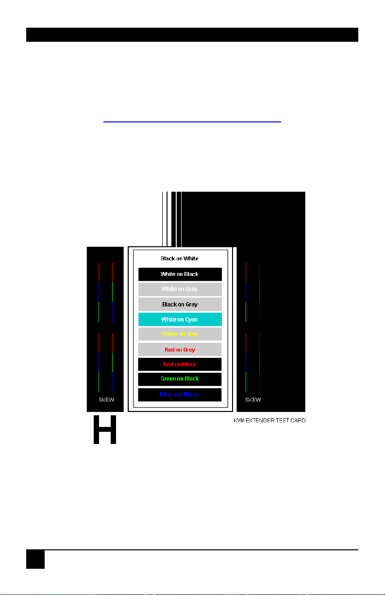
This is an image (see Figure 12) created and used by the manufacturer for video
optimization purposes. It is particularly useful for correcting skew. If you are unable to
view the test card, display some text in a large font on a white background.
You should also open up other application windows to check the clarity
of text in toolbars and icons on the desktop.
Figure 12 Online test card available at
ftp://ftp.blackbox.com/connectivity/ServSwitch/
2. Enter Command Mode (see Command Mode, page 31) by pressing the following key
combination on the remote console’s keyboard:
<Left Control> + <Left Shift> + <F10>
32
Page 35
REMOTE UNIT CONFIGURATION & OPERATION
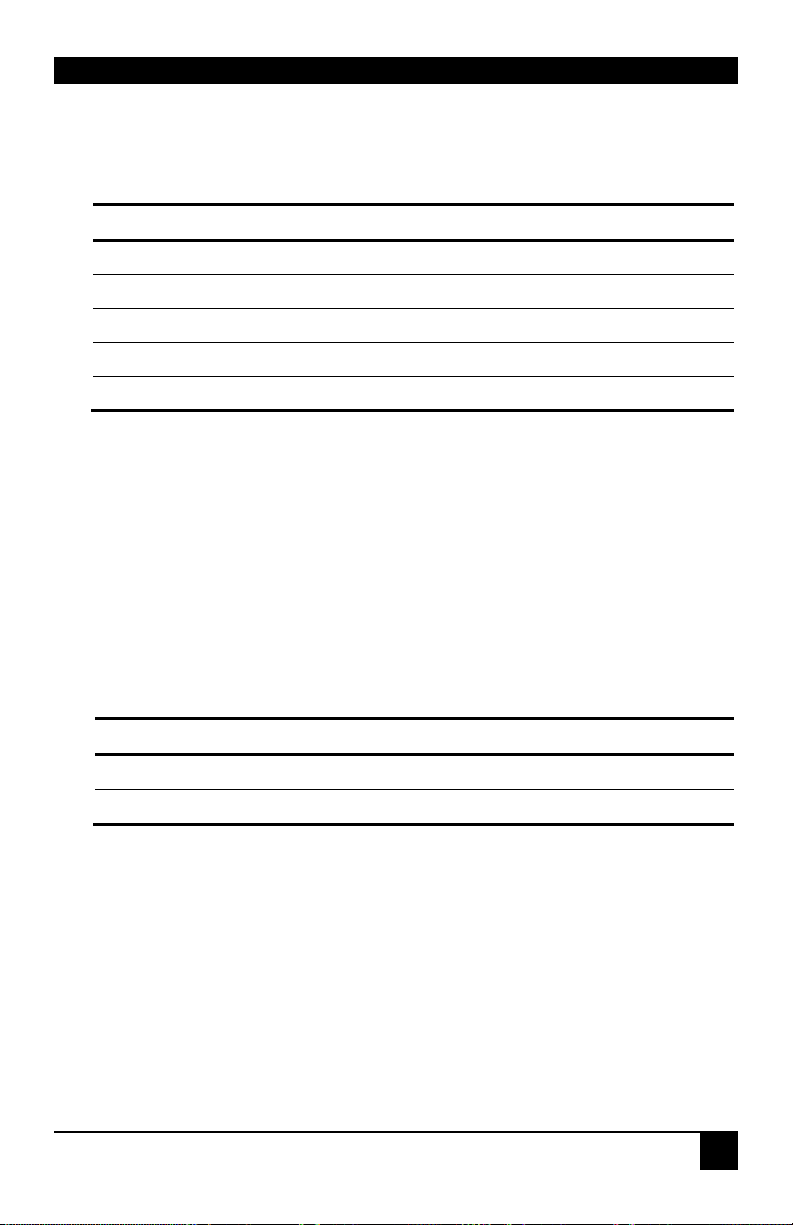
3. Select the video cha nnel you want to configure using one of the following keys (not on
the numeric keypad):
Channel Command Key
Select Channel 1 For Adjustment
Select Channel 2 For Adjustment
Select Channel 3 For Adjustment
Select Channel 4 For Adjustment
Select ALL Video Channels <0> (Channel 0)
<1>
<2>
<3>
<4>
Use Channel 0 to tune all video channels simultaneously. This simplifies
the procedure for setting up large multi-head installations where a
consistent cable type is used and the adjustments required should be
almost the same.
4. Reset the selected channel(s) by pressing:
<Left Control> + <Home>
5. Step through the Assisted EQ settings to find the level that gives the best image.
Assisted EQ Command Key Sequence
Next Assisted EQ Setting
Previous Assisted EQ Setting
<Left Control> + <PgUp>
<Left Control> + <PgDn>
Assisted EQ steps through a table of preset LF & HF EQ values for
different lengths of cable (in 80ft {25m} increments calibrated from 0 to
1250ft {375m}). Each time you enter Command Mode and start adjusting
Assisted EQ, the unit resets LF and HF values.
After finding the best setting, you will probably want to fine-tune the LF and
HF equalization settings (see steps 8&9). This is best done after adjusting for
any color skew as described below.
33
Page 36
SERVSWITCH™ BRAND CATX KVM EXTENDER FAMILY
LF too low
HF too low
LF too high
HF too high
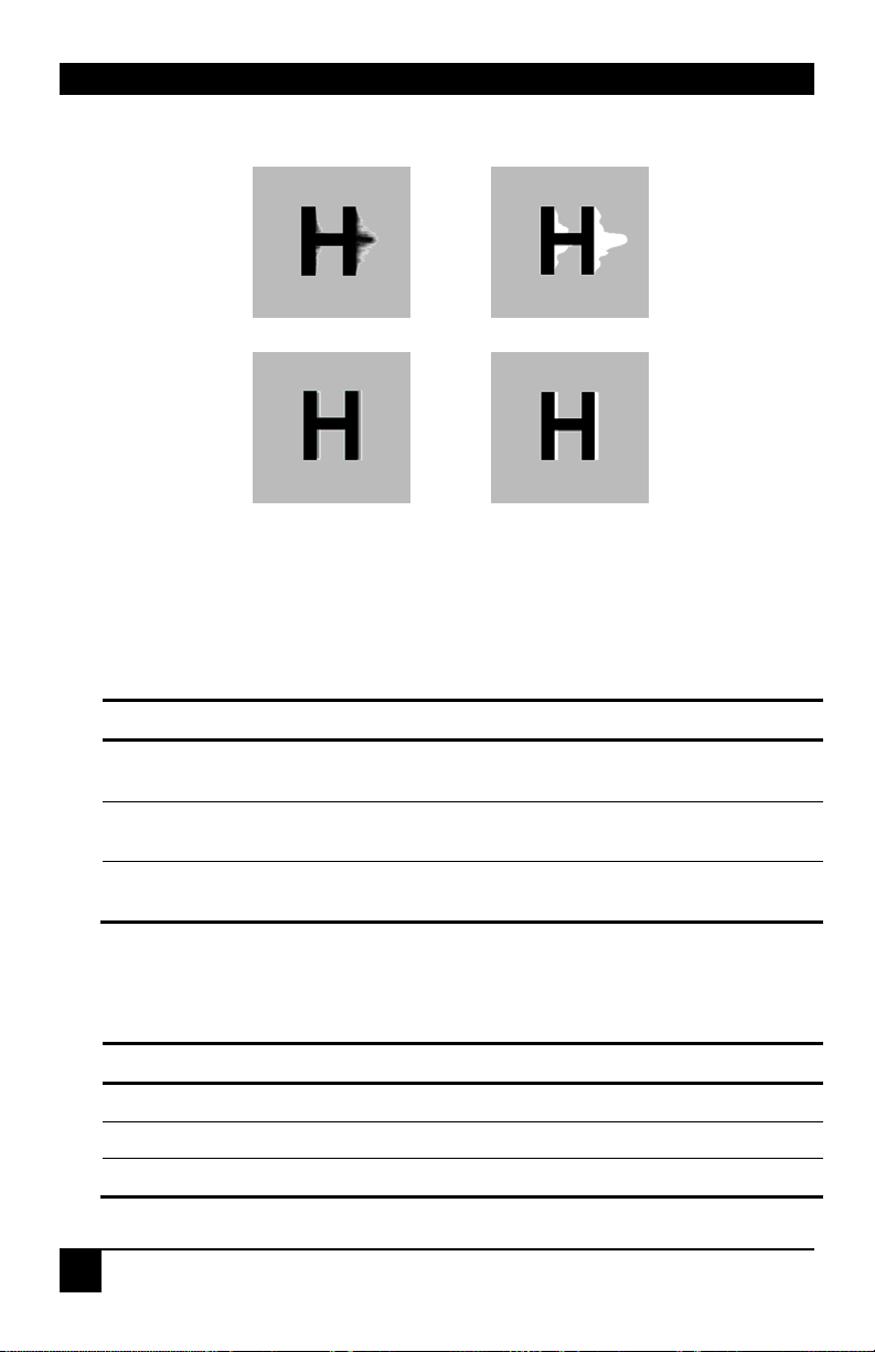
Figure 13 Problems with smearing and sharpness requiring LF and
HF adjustment
6. Identify the ‘slowest’ color – the colored line furthest to the right. Delay the signals of
the two other colors using the following commands:
Delay Command Key Sequence
Increase RED Delay (move right)
Decrease RED Delay (move left)
Increase GREEN Delay (move right)
Decrease GREEN Delay (move left)
Increase BLUE Delay (move right)
Decrease BLUE Delay (move left)
Use the Quick Skew feature to determine which color requires delaying or to quickly set
the delay on a color back to zero. Applying Quick Skew to a color toggles its delay
between zero and 19nS (a typically required value).
<R> + <Right Arrow>
<R> + <Left Arrow>
<G> + <Right Arrow>
<G> + <Left Arrow>
<B> + <Right Arrow>
<B> + <Left Arrow>
Quick Skew Command Key Sequence
Toggle RED Delay
Toggle GREEN Delay
Toggle BLUE Delay
<Left Control> + <R>
<Left Control> + <G>
<Left Control> + <B>
34
Page 37
REMOTE UNIT CONFIGURATION & OPERATION
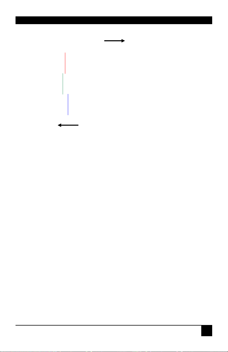
Figure 14 Illustration of skew and appearance on test card
Some Cat5e/Cat6 cables require a large green delay. Video quality can
be often be vastly improved by using standard crossover patch cables at
both ends of the link rather than straight patch cables. For details see
Appendix D: Advanced Cabling Issues (Skew), page 56.
Sometimes the optimum skew adjustment will actually be one step out from that
suggested by the test card due to the way some monitors sample the signal.
The maximum amount of skew correction available is 42nS. This is more than
adequate for the vast majority of cables. However, it may not be enough if you
are using a particularly long run of a cable which exhibits severe delay skew.
7. If you are using one or more flat panel monitors in the remote consoles, carry out
auto-adjustment as described in the monitor’s documentation. Sometimes manual
adjust of clock and/or phase is also required for optimum results and minimization
of jitter.
Slower
Red
Green
Blue
Faster
In this illustration, Blue is the
slowest signal. To optimize the
image, Red and Green need to
be delayed until they align with
Blue.
35
Page 38

SERVSWITCH™ BRAND CATX KVM EXTENDER FAMILY
8. Optionally, fine-tune the LF equalization to remove ‘black video smearing’ - black
smears to the right of large objects such as window title bars (see Figure 13).
LF Equalization Commands Key Sequence
Increase LF Equalization (Coarse)
Decrease LF Equalization (Coarse)
Increase LF Equalization (Fine)
Decrease LF Equalization (Fine)
9. Optionally, fine-tune the HF equalization to sharpen the video image. Increase HF
Equalization until a white edge to the right of small characters just starts to appear (see
Figure 13).
HF Equalization Commands Key Sequence
Increase HF Equalization (Coarse)
Decrease HF Equalization (Coarse)
Increase HF Equalization (Fine)
Decrease HF Equalization (Fine)
<L> + <Up Arrow>
<L> + <Down Arrow>
<L> + <Right Arrow>
<L> + <Left Arrow>
<H> + <Up Arrow>
<H> + <Down Arrow>
<H> + <Right Arrow>
<H> + <Left Arrow>
On certain monitors, you may obtain a sharper image by
overcompensating HF EQ and then decreasing LF EQ to remove any
bright streaks.
10. If you are using one or more flat panel monitors in the remote consoles, carry out auto-
adjustment again.
11. Save the settings by pressing the <Esc> key. Alternatively, to discard any changes and
revert to the settings stored in the EEPROM, press <Left Control> + <Esc>. The
Remote Unit automatically exits Command Mode afte r 30 se c of inac ti v ity and saves all
settings, including any changes.
36
Page 39

REMOTE UNIT CONFIGURATION & OPERATION
4.5 Other Remote Configuration & Operation
Options
Reset Commands
The ServSwitch™ Brand CATx KVM Extender Series has a number of commands to reset the
keyboard and mouse, to reset EQ and Delay values and to restore the factory default
configuration.
Command Key Sequence
Reset Mouse and Keyboard <F1>
Resets the remote console’s keyboard and mouse and then automatically exits Command
Mode. You may need to do this if you have hot-plugged a keyboard or mouse and it has not
initialized correctly.
Mouse Recovery <F3>
Use this command if you experience erratic movement of the mouse pointer or you have lost
mouse movement after hot plugging the Local Unit into the CPU. In the case of erratic
mouse movement, you may need to enter the command a number of times to re-synchronize
the mouse signal. Alternatively, stop moving the mouse for a few seconds and the operating
system’s mouse drivers may automatically re-synchronize the signal. If the Local Unit has
been hot-plugged, this command will issue a request to the OS to initialize the mouse. Use
this command with care.
Reset EQ Values <Left Control> + <End>
You can use this command to zero HF & LF EQ values for the selected video channel(s).
Current color delay values are not affected.
Reset EQ & Delay Values <Left Control> + <Home>
Set all video EQ (HF & LF) and color delay values to zero for the currently selected video
channel(s).
You can use this command to reset EQ and delay values for all video channels in a multihead installation by selecting Channel 0 prior to issuing this command.
Set Extender To Default State <Left Control> + <F9>
Sets ALL extender settings (video & configuration) back to the factory defaults and then
exits Command Mode.
37
Page 40

SERVSWITCH™ BRAND CATX KVM EXTENDER FAMILY
Private Mode Commands
On dual access systems, the remote user can lock out the local console by triggering a
‘Private Mode’ function. This prevents the local console from being used even if the twosecond inactivity timeout period expires.
To lock out the Local Unit:
1. Enter Command Mode:
<Left Control> + <Left Shift> + <F10>
2. Press the <Scroll Lock> key on the Remote Unit keyboard.
To indicate that the Private Mode session is active, the extender system:
• Slowly flashes the Scroll Lock LED on the remote keyboard.
• Illuminates all three LEDs on the local keyboard.
• Displays a blank image on the local console’s monitor.
• Locks the local console’s keyboard and mouse.
To cancel the Private Mode, press <Scroll Lock> again while in Command Mode. This
command also closes Command Mode.
This command only applies to operation with Local Units (standalone and
rack) that have firmware versions ‘S50’ and above. The firmware-revision
level is printed on the base of the extender unit (see Appendix F: Calling
Black Box, page 61).
38
Page 41

REMOTE UNIT CONFIGURATION & OPERATION
Local Unit Configuration Commands
On dual access systems, a local console user can lock out the remote console (see Local
Console Commands, page 42). There are two commands for configuring this feature from
the remote console:
Command Key Sequence
Local Unit Initial Hot Key <F7>
For Local Unit firmware versions ‘S50’ and above only
(all ServSwitch™ Brand CATx KVM Extender Series and CAT5 KVM Extender Series
with Audio/Serial)
To disable the remote console (and start a Private mode session) a local console user must
press an initial ‘hot’ key followed by <Scroll Lock>. By default, the initial ‘hot’ key is
<Right Control> but this can be changed to <Left Control> from within Command
Mode. The setting is stored in EEPROM.
To toggle the Local Unit initial ‘hot’ key, enter Command Mode and then press <F7>. The
console automatically exits from Command Mode after you use this command.
Local Unit Scroll Lock Key Mode <F5>
For Local Unit firmware versions below ‘S50’ only
(for example, ACU1009A, ACU1006DRA, and ACU3009A)
In firmware versions earlier than ‘S50’, a local console user can disable the remote console
(and start a Private mode session) simply by pressing <Scroll Lock>. An initial ‘hot’ key
is not required. In these cases, the Scroll Lock key is not passed to the CPU.
From within Command Mode, you can restore normal Scroll Lock operation. This disables
the Private mode feature on the local console.
To toggle between Private mode and normal Scroll Lock key operation on the local
console, press <F5>. The setting is stored in EEPROM. The console automatically exits
from Command Mode after you use this command.
On the remote console, the Scroll Lock key will always function as
normal. However, the Scroll Lock LED is used to show Private Mode
status. If the Scroll Lock key is assigned to Private Mode (default), then
the remote console’s Scroll Lock LED will not light when <Scroll Lock>
is pressed.
39
Page 42

SERVSWITCH™ BRAND CATX KVM EXTENDER FAMILY
5. Local Unit Operation
5.1 Overview
You need to read this section if you have purchased an extender system kit containing both a
Local and Remote Unit.
For more information about serial/audio port operation, see Appendix E: Audio/Serial
Ports, page 59.
Keyboard and Mouse Emulation
Local Units have keyboard and mouse emulation. The attached PC operates normally without
requiring a keyboard or mouse to be attached to either the Remote or Local Units (in the case
of a dual access system). You can therefore replace any keyboard or mouse attached to the
extender system without disrupting the operation of the computer.
Power
NEVER CONNECT THE REMOTE UNIT 9V POWER SUPPLY TO
A LOCAL UNIT: YOU WILL DAMAGE THE EXTENDER SYSTEM.
Single Head Video
Local Units normally take power from the keyboard connection to the computer. For video
only applications, you must apply external power through this port. Use an external 5V PSU
with PS/2 MiniDIN connector.
Dual Head Video
Local Units (ACU2201A and ACU2222A) may require an external 5V PSU (PSU1006E-R3):
• For video only applications.
• If the PC cannot provide sufficient power through the keyboard connection.
If this is the case, the power LED on the front of the Local Unit will be dim (See Figure 9).
Contact Technical Support for further information.
40
Page 43

LOCAL UNIT OPERATION
5.2 Dual Access Systems
ACU2009A and ACU2028A models offer dual access from consoles at both Remote and
Local Units. This operates on a first-come, first-served basis. When one console is in use, the
system blocks out the other console until there is no keyboard or mouse use at the active
console for two seconds. Both monitors show the current activity on the computer
irrespective of which console is in use.
Certain commands are available at th e Local Unit.
To enter these commands:
1. Press and release the initial ‘hot’ key.
By default, the initial ‘hot’ key is <Right Control>.
2. Press and release the command key.
Changing the Initial Hot Key
The Local Unit’s initial ‘hot’ key may be toggled between <Right Control> and
<Left Control> by entering a configuration command on the remote keyboard (See Local
Unit Configuration Commands, page 39).
41
Page 44

SERVSWITCH™ BRAND CATX KVM EXTENDER FAMILY
Local Console Commands
After pressing the initial ‘hot’ key on the local keyboard, you can issue a number of
commands by pressing additional keys. These commands allow you to start a private mode
session on the local console or to reset the keyboard and mouse.
These commands only apply to Local Units and Rack hubs having firmware
versions ‘S50’ and above.
Command Key Sequence
Private Mode <Scroll Lock>
Local Units that feature dual access (ACU2009A, ACU2028A) allow the local user to lock
out the remote console by triggering a ‘Private Mode’ function. This prevents the remote
console from being used even if the two second inactivity timeout period expires.
During a Private Mode session, the extender system:
• Flashes the Scroll Lock LED on the local keyboard.
• Illuminates all three LEDs on the remote keyboard.
• Displays a blank image on the remote console’s monitor.
• Locks the remote console’s keyboard and mouse.
Reset Local Keyboard and Mouse <Num-Pad Up Arrow>
Resets the local console’s keyboard and mouse. You may need to do this if you have hotplugged a keyboard or mouse and it has not initialized correctly.
Mouse Recovery <Num-Pad Left Arrow>
Use this command if you experience erratic movement of the mouse pointer or you have lost
mouse movement after hot plugging the Local Unit into the CPU. In the case of erratic mouse
movement, you may need to enter the command a number of times to re-synchronize the
mouse signal. Alternatively, stop moving the mouse for a few seconds and the operating
system’s mouse drivers may automatically re-synchronize the signal. If the Local Unit has
been hot-plugged, this command will issue a request to the OS to initialize the mouse. Use
this command with care.
42
Page 45

TROUBLESHOOTING
6. Troubleshooting
6.1 Video
The image is not sharp, or is badly smeared.
Have you adjusted the video equalization? Follow the instructions on page 30.
Check the Interconnect cable between the Remote and Local Units. Is it of the
recommended type (see page 19)? Is it intact along its entire length and securely
connected at both ends? Is it wired correctly (see page 57)?
Ensure that all video connections throughout the system are attached securely.
Are you using an LCD panel? You need to adjust its clock and/or phase.
Colors appear to be separated and there are colored borders on text and icons.
Have you tuned the video signal and set delays to correct skew? Follow the
instructions on page 30. See Appendix D for advanced cabling information.
Check the Interconnect cable between the Remote and Local Units. Is it of the
recommended type (see page 19)? Is it intact along its entire length and securely
connected at both ends? Is it wired correctly (see page 57)?
I can’t get enough color delay to correct skew.
See Appendix D: Advanced Cabling Issues (Skew), page 56.
I can’t get rid of bright ‘ringing’ after characters.
See Appendix D: Advanced Cabling Issues (Skew), page 56.
I only need video extension – not keyboard or mouse - but I can’t get a picture.
Have you powered the Local Unit? The Local Unit gets its power from the CPU
through the keyboard connection and it will not operate without it. Use an external
5V PSU as described on page 40.
43
Page 46

SERVSWITCH™ BRAND CATX KVM EXTENDER FAMILY
The monitor sometimes goes blank for a second or two.
Check that the interconnect cable is not routed near power lines or other sources of
electrical interference. Use shielded STP/FTP cable instead of UTP cable ensuring
that the shield connection is maintained between the extender units.
Check system grounding. The Remote Unit has an isolated power supply and relies
on obtaining a ground reference through the connected monitor. Some monitors on
the market have an external PSU which itself may be isolated from power ground.
If this is the case, and you are experiencing monitor blanking, you may need to
consider grounding the Remote Unit chassis (to power ground) or replacing the
monitor’s power supply with a non-isolated model.
If this is a persistent problem, contact Technical Support.
The PC won’t boot into the correct graphics mode.
The extender includes DDC emulation for all standard resolutions and there should
not normally be any issues.
For non-standard resolutions, you will need to explicitly set the resolution in your
operating system configuration ignoring the DDC data read from the Local Unit.
Contact Technical Support if you have problems selecting your required graphics
mode.
Jitter is evident on video.
Adjust the clock and/or phase on your flat-panel. Contact Technical Support if this
fails to improve the situation.
Are you testing a system using a coiled drum of CATx cable? Try uncoiling the
cable. If this solves the video jitter, you should not have a problem after full
installation.
The image is not stable and is blanking regularly.
Re-power the Remote Unit.
Can the extender be used with RGB video?
Yes.
There is a slight color change when I increase delays to correct skew.
With certain monitors, there may be a slight color change when you increase the
color delay. This is due to a contrast change on that particular color and may easily
be compensated for by adjusting the monitor’s color balance.
44
Page 47

TROUBLESHOOTING
6.2 Keyboard & Mouse
When I am typing, I get wrong or missing characters on the screen.
Your keyboard may be in the wrong mode. Use the appropriate commands to reset
the keyboard and mouse as described in the sections covering local and remote
operation.
The PC comes up with ‘keyboard error’.
Press <F1> or <ESC>. If the keyboard now operates correctly, you need to adjust
the BIOS setup to disable keyboard testing during booting.
The system does not detect a PS/2 mouse.
If connecting the Local Unit to a live system, connect the mouse cable to the CPU
before keyboard connection to ensure the mouse is enabled correctly. Try issuing
the Mouse Recovery command.
Check that the mouse cable is connected properly and securely. Reboot the system.
The mouse pointer moves erratically.
Reset the keyboard and mouse.
Issue the Mouse Recovery command up to three times.
Ensure that you have the latest driver for your mouse.
If you are using the extender with a KVM switch, command the switch to reset the
mouse.
Quit and restart the application. Reboot the PC.
When I ‘hot-plug’ the Local Unit, the mouse no longer moves.
When connecting the Local Unit to a live system, connect the mouse cable to the
CPU before keyboard connection to ensure the mouse is enabled.
Try issuing the Mouse Recovery command.
Some of the mouse buttons don’t work.
The CATx Extender units support standard 2/3-button mice (with or without a
wheel). Additional buttons will not operate.
I have an enhanced keyboard with extra keys and indicators. Everything works apart from
these additional features.
As standard, the extender only emulates a generic PS/2 keyboard. To support other
keyboards (or cascaded KVM switches), special firmware offering a transparent
mode may be required. Please contact Technical Support to discuss your
application.
45
Page 48

SERVSWITCH™ BRAND CATX KVM EXTENDER FAMILY
6.3 Audio
The audio is very quiet.
The audio I/O is line-level and requires amplified speakers and connection to
devices providing line-level I/O.
The audio is loud but distorted.
Check that the audio input is not greater than line level (4V peak-to-peak). The
KVM extender accepts line-level audio input only.
The microphone output is barely audible.
See Appendix E: Audio/Serial Ports, page 59.
6.4 Serial
My serial device does not function.
The extender supports serial devices at data rates not exceeding 19.2K Baud
(although 38.4K operation might be possible with certain equipment).
Check the type of flow control used by the device and CPU. The extender supports
RTS, CTS, DTR, and DSR. Some systems may require a wiring adapter to transfer
RI and DCD.
Attach the device directly to the serial port on the PC and test whether the problem
is a PC or extender problem.
Some serial devices cannot be hot-plugged. Try connecting the device to a powered
Remote Unit prior to booting the system.
46
Page 49

TROUBLESHOOTING
6.5 General Questions
Is it possible to use a cable length longer than 1000ft (300m)?
It might be possible to use a cable of up to 1650ft (500m) at lower resolutions.
However, we do not recommend this and cannot guarantee that it will work.
Can the extender be daisy chained?
In certain circumstances, it is possible to cascade extenders, though we do not
recommend doing so. Careful consideration needs to be given to extender setup,
and the electrical environment. If you plan to cascade extenders, please contact
Technical Support.
Which interconnection cable is best?
The extender will operate with either shielded (STP/FTP) or unshielded (UTP)
CATx cable. However, correctly installed shielded cable is preferred, especially in
electrically noisy environments, because it resists interference more strongly, limits
ground potential differences, and reduces emissions. To benefit from shielded cable
the shield connection must be maintained from end to end through any intervening
patch cables, panels and RJ45 connectors.
Please note that shielded cable is advised in order to maintain regulatory EMC
compliance.
Can the extender system be used between buildings?
No. Ground loops could damage the extender system and attached equipment.
Can multiple Local/Remote Units be used by swapping the interconnection cable?
Local Units provide full keyboard and mouse emulation, so it is possible to swap or
switch the local-remote interconnection to create a KVM matrix-switch system.
Sometimes you may need to reset the keyboard and mouse (by entering the
appropriate command) after a swap or switch. Please call Technical Support before
deploying such a system.
Can the extender be connected into our network?
Absolutely not. Regardless of the cable similarities, the data signals and voltages
used by the extender are different from those used by Ethernet and other types of
networks. Connecting the extender to a LAN hub, switch, repeater, or other
network device, or exposing it to the signal levels present on network data lines
may damage the extender and other devices.
47
Page 50

SERVSWITCH™ BRAND CATX KVM EXTENDER FAMILY
Appendix A: Example Applications
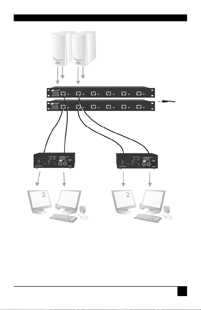
This section illustrates four specific applications using extender units:
• Six dual-monitor consoles with serial and audio (Figure 15).
• Six remote serial touch screens with local access through a KVM switch (Figure 16).
• Information distribution system sharing a single PC at up to six remote locations (Figure
17).
• Extender system with second screen for security monitoring (Figure 18).
For more specific information about these, or any other complex applications, please discuss
suitable extension architecture with your Technical Support.
48
Page 51
APPENDIX A: EXAMPLE APPLICATIONS
A
A
A
A
CU1006VRA Extender Hub
Takes primary video, keyboard,
mouse, audio and serial signals from
each CPU (only two shown).
5V PSU
CU1006RA Extender Hub
Takes secondary video from each
CPU. 5V PSU required.
CURA002
Remote Units connect
to KVM console and
secondary monitor.
Figure 15 Dual-monitor consoles with serial and au dio extension
49
Page 52
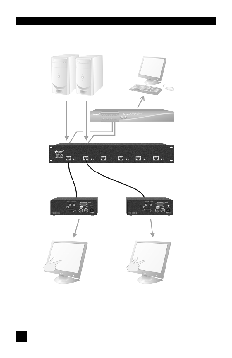
SERVSWITCH™ BRAND CATX KVM EXTENDER FAMILY
A
A
A
™
ServSwitch
Local access ports connect to single
KVM console through a ServSwitch™
brand KVM switch.
CU1006DVRA Extender Hub
Takes KVM and serial signals
from each CPU (only two shown).
CURA001
Remote Units connect
to touch screens.
Figure 16 Touch screen network with local access to CPU through
KVM switch
50
Page 53
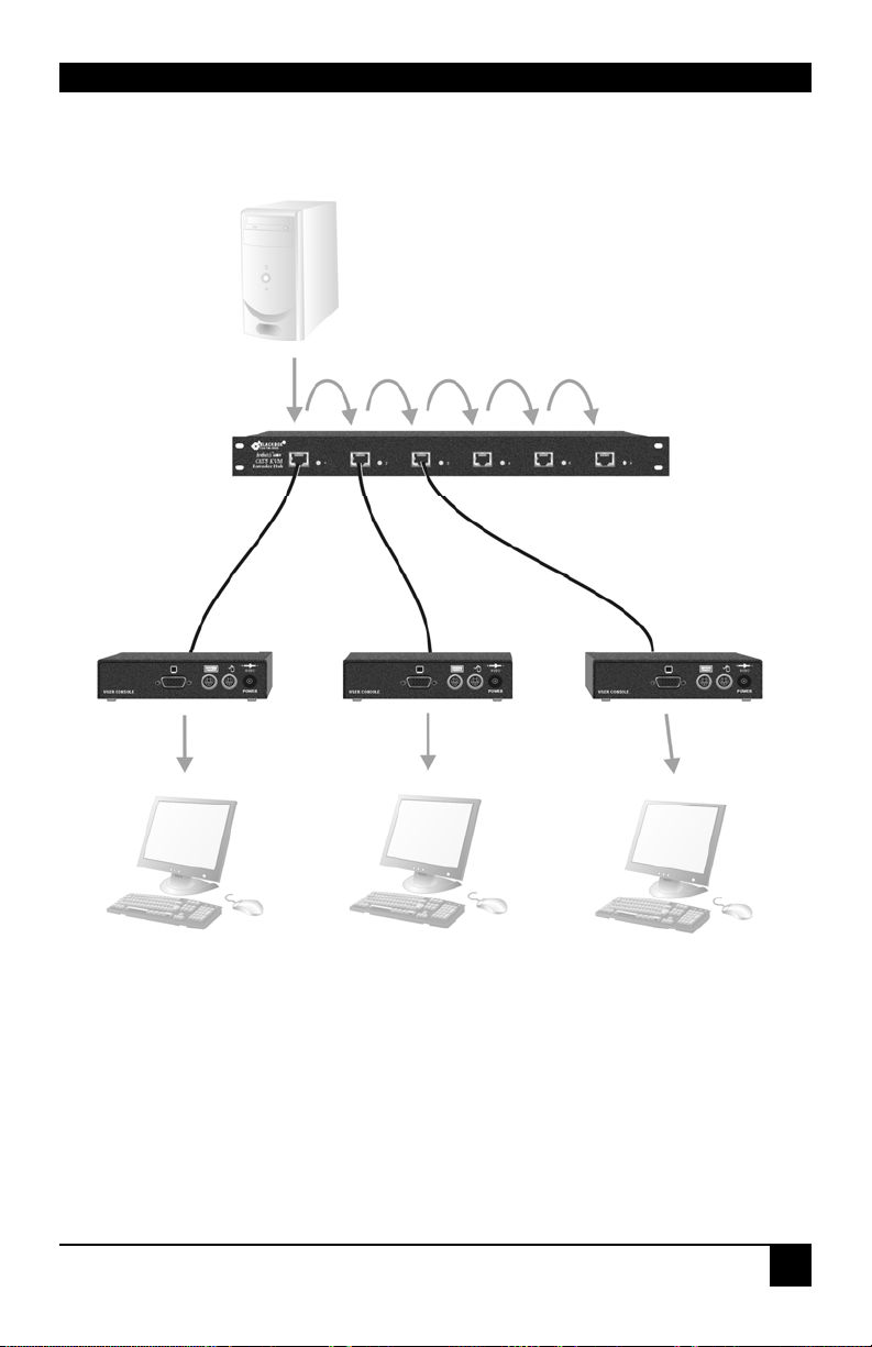
APPENDIX A: EXAMPLE APPLICATIONS
A
A
CU1006DRA Extender Hub
CPU connects to Port 1. Local access ports are
daisy-chained to allow operation from any console
and/or video to be distributed to multiple locations.
ACUR001
Remote Units connect
to KVM consoles.
Figure 17 Information distribution system sharing a single PC
51
Page 54
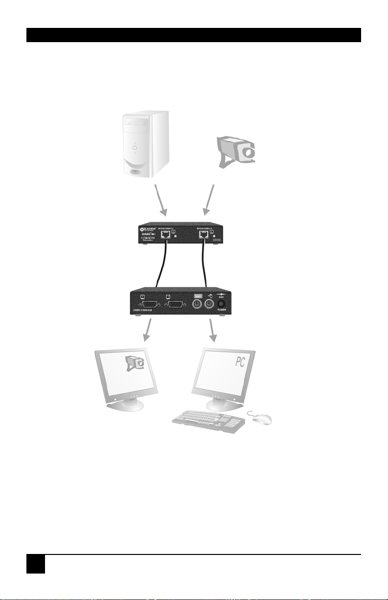
SERVSWITCH™ BRAND CATX KVM EXTENDER FAMILY
A
A
A
Security System
Provides secondary
video input.
ACU2201
Takes KVM signals from
standard PC and secondary
video from security system.
CUR002
Connects to KVM console.
Secondary monitor used for
security monitoring.
Figure 18 Extender system with second screen for security monitoring
52
Page 55
APPENDIX B: RACK MOUNT OPTIONS
Appendix B: Rack Mount Options
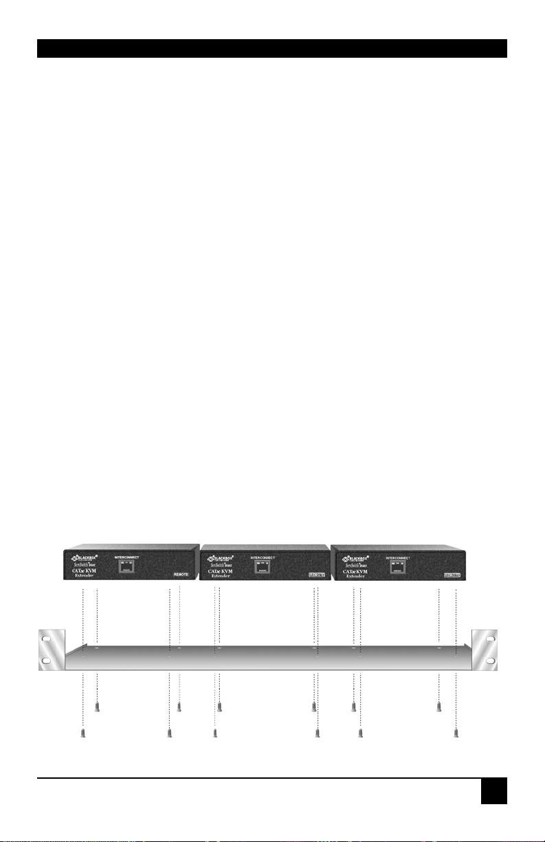
Most of the extender units can be mounted in a 19” rack using one of the two mounting kits:
• RMK19U-X3
• RMK19U-R2
RMK19U-X3 Mounting Kit
RMK19U-X3 allows you to mount up to three of the following units across 1U:
Remote Units:
ACU2001A ACU2009A ACU2022A ACU2028A ACU2201A
ACU2222A ACUR001A ACUR002A ACURA001A ACURA002A
ACUR004A ACURA004A
Local Units:
ACU2201A ACU2222A
The kit contains one rack plate and M3 countersunk mounting screws.
To mount a unit:
1. Remove the feet from the extender unit.
2. Align the holes on the base plate with the vacant screw holes on the base of the extender
unit.
3. Fasten the base of the unit to the plate of the mounting kit using the supplied screws.
Figure 19 RMK19U-X3 Mounting Kit
53
Page 56
SERVSWITCH™ BRAND CATX KVM EXTENDER FAMILY
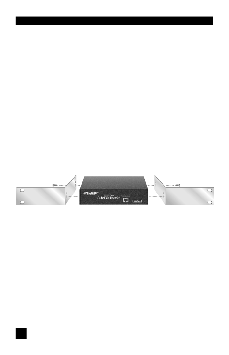
RMK19U-R2 Mounting Kit
RMK19U-R2 allows you to mount one of the following Local Units across 1U:
• ACU2001A
• ACU2022A
• ACU2009A
• ACU2028A
The kit consists of two angled brackets.
To mount a unit:
1. Remove the two screws from one side of the unit.
2. Match up the lower pair of holes on a bracket with the vacant screw holes on the side of
the unit.
3. Using the original screws, fasten the mounting brackets to the side of the unit.
4. Repeat this procedure on the other side of the unit.
5. Fasten the assembly to the rack unit.
Figure 20 RMK19U-R2 Mounting Kit
54
Page 57

APPENDIX C: REMOTE UNIT: FLASH UPGRADING
Appendix C: Remote Unit: Flash Upgrading
& External Configuration
The Remote Unit contains a configuration port accessed through the mouse port. By attaching
an upgrade cable between this port and the serial port on any PC (or laptop) the Remote
Unit’s firmware may be upgraded. In addition, all configuration settings may be saved,
adjusted and restored. This could be useful in large system roll-outs where similar length
cables are used (by avoiding the need to fully set up each Remote Unit individually).
To operate the configuration port, you need:
• A laptop or PC close to the Remote Unit running Windows. The Remote Unit only has
to be powered and does not need to be connected to the Local Unit.
• An upgrade cable connected between the mouse port and the laptop or PC’s serial port
(Part No: ACUFLH-R2).
• A software utility called ‘ConfigXt’.
• The firmware upgrade file.
The application, detailed instructions and firmware upgrades may be downloaded online.
Please consult Technical Support for details on how to do this.
Local Units are not currently flash-upgradeable.
55
Page 58

SERVSWITCH™ BRAND CATX KVM EXTENDER FAMILY
Appendix D: Advanced Cabling Issues (Skew)
The suggestions made in this Appendix should only be investigated if you cannot obtain
satisfactory image quality after configuring the Remote Unit (as described in Section 4). The
techniques described here are usually only necessary when you are operating at the highest
screen resolution (1600x1200) with long Interconnect cables.
Dealing with Severe Skew
The CATx KVM extender provides a maximum skew compensation of 42nS. This is more
than adequate for most cables. However, it may not be enough if a particularly long cable is
used that exhibits severe delay skew. In this case, some of the procedures described below
should be considered. In extreme cases, you should consider using an additional external
delay line (Model: ACUDLY) or an alternative CATx cable as recommended by Technical
Support.
Green Delay
Introducing delays in the video signals inevitably may cause some distortion. For example, it
may result in pixels being sampled twice on TFT screens.
The human eye is extremely sensitive to green distortion. To obtain optimal video
performance it is best to ensure that no green delay is required. You can visually check the
relative pair delays by viewing the test card (without any delays applied). The two color bars
on the left require delaying, but the color bar on the right requires zero delay (slowest) and is
the reference. Ideally, green should be the reference signal.
If your system requires a large delay on the green signal, try using a
crossover patch cable at each end of the link (instead of straight patch cables
to connect to wall outlets). In many cases, the crossover should transfer the
delay requirement to the blue signal rather than green. The human eye is
much less sensitive to blue distortion and so video quality can be improved.
Check the result using the test card and adjust the delays accordingly. The
main cable should be wired according to EIA-568B as show n bel ow.
56
Page 59

APPENDIX D: ADVANCED CABLING ISSUES (SKEW)
Cable Pinning/Pairing
The following table illustrates which RJ45 connector pins the extenders use for various
signals. It also details the standard EIA-568B wiring scheme that is recommended for most
installations.
Looking into the RJ45 socket on a Remote Unit, Pin 1 is on the right and Pin 8 on the left.
Pin Color
(EIA-568B)
1
2
3
6
4
5
7
8
Using a crossover cable (at each end) will put the green video on the orange colored pair and
the blue video on the green colored pair.
White/Orange
Orange/White
White/Green
Green/White
Blue/White
White/Blue
White/Brown
Brown/White
Signal
Blue Video
Green Video
Red Video
Data
EIA-568A wiring can also be used. Contact Technical Su p port for details.
57
Page 60

SERVSWITCH™ BRAND CATX KVM EXTENDER FAMILY
Optimizing Pairs (General Solution)
Measure pair lengths with a LAN cabling tester (TDR) or view pairs by stripping back a
small piece of cable and viewing how tightly pairs are twisted. The most tightly twisted pair
is the slowest (longest) and the loosest pair the fastest (shortest). You can also check the
relative delays using the test card as described on page 30.
The table below shows the general solution for optimizing CATx cabling for video in order of
pair length.
Pins Pair Signal
7 & 8 Shortest Pair Data
1 & 2 3rd Longest Pair Blue Video
4 & 5 2nd Longest Pair Red Video
3 & 6 Longest Pair Green Video
Some cables have a ‘3+1’ construction where three pairs closely match. The fourth pair
should be used for data and the other pairs sorted as in the above table.
Other cables have a ‘2+2’ construction where there are two sets of dissimilar pairs. Put red
and green on one set (tightest) and blue & data on the other.
A suitable pair-swapping scheme is easily made using custom wired patch cables at each end.
58
Page 61

APPENDIX E: AUDIO/SERIAL PORTS
Appendix E: Audio/Serial Ports
Operation & Multi-Port Configuration
This appendix describes audio & serial interface operation for those models that have this
feature:
• ACU2022A
• ACU2028A
• ACU2222A
• ACURA001A
• ACURA002A
• ACURA004A
These extender products contain daughter boards that allow bi-directional stereo audio and a
full-duplex serial data link to be sent across the CATx interconnection cable in addition to
PS/2 keyboard, mouse and video.
Serial Interface - Set Up and Operation
No setting up or user adjustments are required. Please note that on dual access Local Units,
the serial link is always active.
The Remote Unit’s serial port is wired as DTE - the same as that on a PC. To connect a serial
printer or other DTE (rather than DCE device) to the Remote Unit, you will need a NullModem crossover cable between the Remote Unit and the printer. Select Xon/Xoff software
flow control on the printer and PC.
A serial touch screen may be plugged directly into the Remote Unit.
Serial Interface – Handling Multiple Serial Devices
The extender’s serial interface transmits/receives six signals (3 signals in each direction).
Normally, four of these signals are used for hardware handshaking (in addition to TX & RX).
However, because each handshaking line can support signals up to 19,200 Baud it is possible
to configure the serial interface to handle up to three simple 2-wire (Tx/Rx only) serial links.
To do this, you will need to construct a custom breakout cable. Please contact Technical
Support for further information.
59
Page 62

SERVSWITCH™ BRAND CATX KVM EXTENDER FAMILY
Audio Interface - Set Up and Operation
The audio interface is line-level and is designed to take the output from a sound card (or other
line-level) source and be connected to a set of powered speakers at the other end of the link.
Stereo audio may be transmitted either way across the link (simultaneously).
No setup is required unless a microphone is connected to the Remote Unit.
Connect the extender as follows:
• Take the line-level output from your sound card (green connector) and connect to ‘Line
In’ on the Local Unit.
• Connect ‘Line Out’ on the Remote Unit to a set of powered speakers.
Audio Interface – Using a Microphone
A microphone may be plugged into the ‘Line In’ connector on the Remote Unit.
There are two ways of setting up a microphone:
• The Local Unit’s ‘Line Out’ connection should normally be wired to the microphone
input (Pink) on your sound card. The sound card should then be set up to provide
additional amplification (+17dB). This is the preferred connection method.
• Alternatively, the Remote Unit itself can provide microphone amplification. To set this,
open up the Remote Unit and locate the jumper labeled ‘MIC’ on the daughter board.
Connect this jumper across the pins. The Local Unit’s ‘Line Out’ connection should then
be wired to ‘Line In’ (Blue) on your sound card.
If your microphone is already amplified, follow the second method but DO NOT install the
amplification jumper in the Remote Unit.
60
Page 63

APPENDIX F: CALLING BLACK BOX
Appendix F: Calling Black Box
If you determine that your CATx KVM Extender is malfunctioning, do not attempt to alter or
repair it. It contains no user-serviceable parts. Contact Black Box Technical Support at 724-
746-5500.
Before you do, make a record of the history of the problem. We will be able to provide more
efficient and accurate assistance if you have a complete description, including:
• The firmware-revision level printed on the bottom of the Extender (very important,
especially for keyboard and mouse problems); The KVM extender’s firmware revision
level:
Version Number Format: xxSyy/zz
xx is the hardware revision number
yy is the firmware revision number
zz is the auxiliary revision number.
• The nature and du ration of the probl em.
• When the problem occurs.
• The components involved in the problem—that is, what type of computers, what type of
keyboard, brand of mouse, make and model of monitor, type and make of CATx cable,
etc.
• Any particular application that, when used, appears to create the problem or make it
worse.
• The results of any testing you’ve already done.
To solve some problems, it might be necessary to upgrade the Extender’s firmware. If this
turns out to be the case for your difficulty, our Technical Support technicians will arrange for
you to receive the new firmware and will tell you how to install it.
Shipping and Packaging
If you need to transport or ship your CATx KVM Extender:
• Package it carefully. We recommend that you use the original container.
• If you are shipping it for repair, please include the Remote Unit’s external power supply.
If you are returning it, please include everything you received with it. Before you ship
the Extender back to Black Box for repair or return, contact us to get a Return
Authorization (RA) number.
61
Page 64

SERVSWITCH™ BRAND CATX KVM EXTENDER FAMILY
Appendix G: Specifications
Video
Maximum Resolution
Video Compatibility
Video I/O
Skew Compensation
Video Compensation
Video Coupling
Sync I/O
Video Input Connectors
Video Output Connectors
Keyboard and Mouse
KB Compatibility
Mouse Compatibility
KB/Mouse Connectors
(CPU)
KB/Mouse Connectors
(Device)
1600x1200@60Hz over 650ft (200m)
1280x1024@75Hz over 1000ft (300m)
Operation at higher resolutions/refresh rates may be
possible at shorter distances
VGA to UXGA, RGB
0.7V P-P
15-stage. 42nS Max. 2.8nS per step
Compensation available on each color
2-stage. Separate LF & HF Equalizers
DC
Separate/Composite TTL Level
Sync on green
Sync Polarity is preserved
HD15 (Male) on Single-Head Local Units
DB25 (Female) on Dual-Head Local Units (KVM)
HD15 (Female)
PC/AT, PS/2
Standard PS/2 two/three button
Standard wheel mice
Logitech 3-button PS/2
6-Pin MiniDIN Socket (Single-Head Local)
DB25 (Female) on Dual-Head Local Units
(KVM)
6-Pin MiniDIN Socket
62
Page 65

APPENDIX G: SPECIFICATIONS
Serial Interface
Max Baud Rate Supported
Serial Data Format
Signals Transferred
Local Unit Connector
Remote Unit Connector
Audio Interface
Description
Transmission method
Signal levels
Input Impedance
Local Unit Connectors
Remote Unit connectors
Microphone Support
Power Requirements
19.2K Baud
Transparent
TX, RX, RTS, CTS, DTR, DSR
DB9 Female (DCE)
DB9 Male (DTE)
Bi-directional stereo audio link
Digitized virtually CD quality audio (16-bit, 38.4kHz)
Line level (4 Volts Pk-Pk maximum)
47kΩ
2x3.5mm stereo jack socket (Line In & Line Out)
2x3.5mm stereo jack socket (Line/Mic In & Line Out)
Microphone may be connected to Remote Unit
Pullup resistor provides bias for condenser microphone
Option to set microphone amplification to +17dB
Local Unit
Remote Unit Power Supply
5V at up to 200mA supplied by PC PS/2 keyboard port
External PSU may also be connected
9V, 2A (18W) Regulated
(certified to all relevant safety standards)
Universal IEC Input
Isolated Output
2.5mm DC Jack (Center Positive)
63
Page 66

SERVSWITCH™ BRAND CATX KVM EXTENDER FAMILY
Size and Shipping Weight
ACUR001A, ACUR002A
ACURA001A, ACURA002A
ACUR004A, ACURA004A
ACU2201A
ACU2222A
ACU2001A, ACU2009A
ACU2022A, ACU2028A
Environmental
Remote Unit: 5.6”x5.7”x1.1” (143x145x29mm)
Shipping Weight: 2.7lb (1.2kg)
Remote Unit: 5.6”x5.7”x1.7” (143x145x44mm) (1U)
Shipping Weight: 2.9lb (1.3kg)
Remote Unit: 11.0”x5.7”x1.1” (279x145x29mm)
Shipping Weight: 4.0lb (1.8 Kg)
Local Unit: 5.7”x4.5”x1.1” (146x114x29mm)
Remote Unit: 5.6”x5.7”x1.1” (143x145x29mm)
Shipping Weight: 5.1lb (2.3kg)
Local Unit: 5.7”x4.5”x1.7” (146x114x44mm) (1U)
Remote Unit: 5.6”x5.7”x1.7” (143x145x44mm) (1U)
Shipping Weight: 5.9lb (2.7kg)
Local Unit: 8.0”x3.9”x1.4” (202x100x36mm)
Remote Unit: 5.6”x5.7”x1.1” (143x145x29mm)
Shipping Weight: 5.1lb (2.3kg)
Local Unit: 8.0”x3.9”x1.7” (202 x100x44mm) (1U)
Remote Unit: 5.6”x5.7”x1.7” (143x145x44mm) (1U)
Shipping Weight: 5.9lb (2.7kg)
Operating Temperature
Storage Temperature
Relative Humidity
Chassis Construction
64
32 to 104°F (0 to 40 °C)
-22 to 149°F (-30 to 65 °C)
5-90% non-condensing
Fully shielded. Black painted steel
Page 67

NOTES
Page 68

NOTES
Page 69

Page 70

Order toll-free in the U.S.: Call 877-877-BBOX (outside U.S. call 724-746-5500)
Customer Support Information:
For FREE Technical Support 24 hours a day, 7 days a week, call 724-746-5500 or fax 724-746-0746
Mailing address: Black Box Corporation, 1000 Park Dr., Lawrence, PA 15055-1018
World-Wide Web: www.blackbox.com • Email: [email protected]
© Copyright 2009. Black Box Corporation. All rights reserved.
 Loading...