

Page 1
CUSTOMER
SUPPORT
INFORMATION
Order toll-free in the U.S.: Call 877-877-BBOX (outside U.S. call 724-746-5500)
FREE technical support 24 hours a day, 7 days a week: Call 724-746-5500 or fax 724-746-0746
Mailing address: Black Box Corporation, 1000 Park Drive, Lawrence, PA 15055-1018
Web site: www.blackbox.com • E-mail: info@blackbox.com
JANUARY 2003
ACUDLY
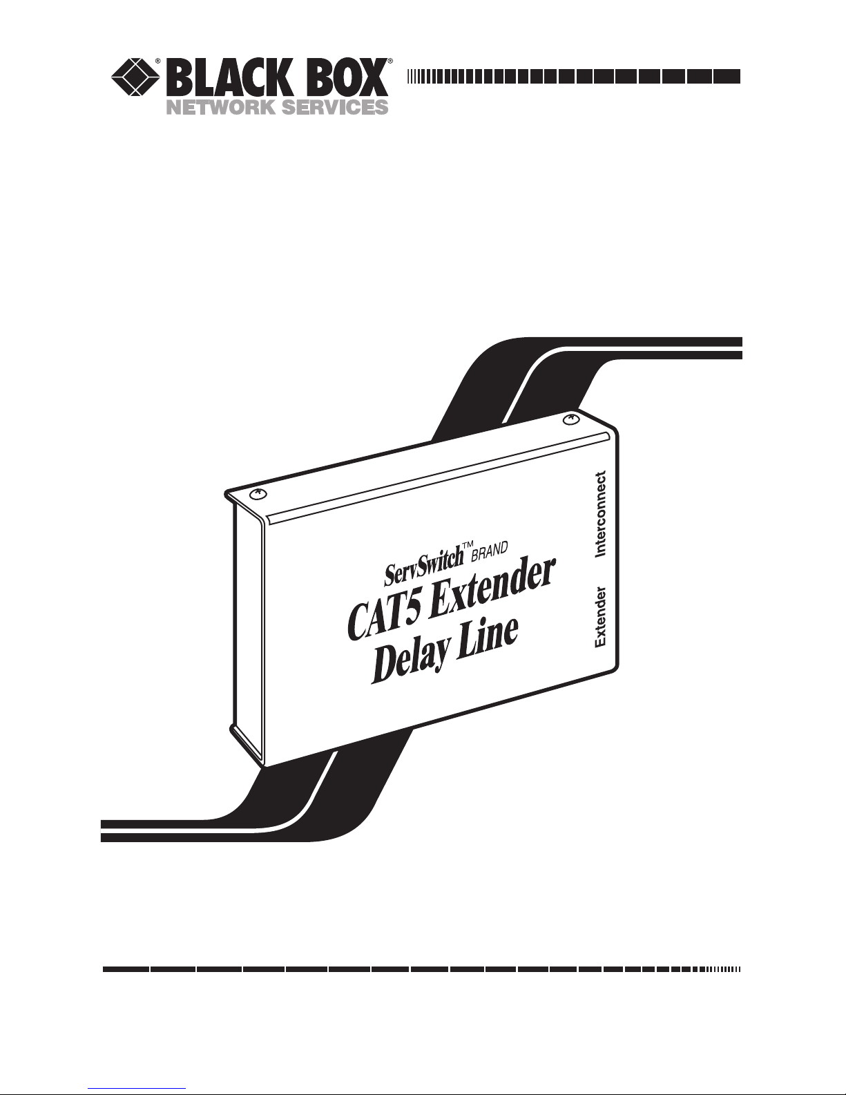
ServSwitch™ Brand CAT5 Extender
Delay Line Module
Page 2

1
THE SERVSWITCH™ FAMILY
Welcome to the ServSwitch™ Family!
Thank you for purchasing BLACK BOX®ServSwitch™ Brand video equipment! We
appreciate your business, and we think you’ll appreciate the many ways that this
product will save you money, time, and effort.
Our ServSwitch family is all about breaking away from the traditional, expensive
model of computer management and display. You know, the one-size-fits-all-even-if-itdoesn’t model that says, “One computer gets one dedicated monitor or user station, no
more, no less.” Why not a single user station (monitor, keyboard, and mouse) for
multiple computers—even computers of different platforms? Why not a pair of user
stations, each of which can control multiple computers? Why not many monitors or
user stations for the same computer? Why not access or display any of your computers,
anywhere in the world, with any of your user stations or monitors?
With our ServSwitch products, there’s no reason why not. We carry a broad line of
robust solutions for all these applications:
•
Do you have just two PCs and need an economical alternative to keeping two mice,
keyboards, and monitors on your desk? Or do you need to share many computers,
including a mix of IBM
®
PC, RS/6000®, Apple®Macintosh®, Sun Microsystems®,
and SGI™ types among multiple worldwide users with different access levels?
• Do you have to send video from one computer to two different local monitors? Or
do you need to send video from multiple computers to dozens of remote monitors?
•
Does your switch have to sit solidly on a worktable and use regular everyday cables?
Or does it have to be mounted in an equipment rack, use convenient many-to-one
cables, and have a rackmounted user station that folds and slides into 1U of space?
No matter how large or small your setup is, no matter how simple or how complex,
we’re confident we have a ServSwitch system that’s just right for you. The ServSwitch™
family from Black Box—the one-stop answer for all your video and KVM switching and
extension needs!
*
This manual will tell you all about your new ServSwitch™ CAT5 Extender Delay Line
Module, including how to install, configure, and troubleshoot it. For an introduction to
the
Module, see Chapter 2. The Delay Line product code covered in this manual is:
ACUDLY
Page 3

2
SERVSWITCH™ BRAND CAT5 EXTENDER DELAY LINE MODULE
FEDERAL COMMUNICATIONS COMMISSION AND INDUSTRY CANADA
RADIO-FREQUENCY INTERFERENCE STATEMENTS
This equipment generates, uses, and can radiate radio-frequency energy, and if not
installed and used properly, that is, in strict accordance with the manufacturer’s
instructions, may cause interference to radio communication. It has been tested
and found to comply with the limits for a Class A computing device in accordance
with the specifications in Subpart B of Part 15 of FCC rules, which are designed to
provide reasonable protection against such interference when the equipment is
operated in a commercial environment. Operation of this equipment in a
residential area is likely to cause interference, in which case the user at his own
expense will be required to take whatever measures may be necessary to correct the
interference.
Changes or modifications not expressly approved by the party responsible for
compliance could void the user’s authority to operate the equipment.
This digital apparatus does not exceed the Class A limits for radio noise emission from
digital apparatus set out in the Radio Interference Regulation of Industry Canada.
Le présent appareil numérique n’émet pas de bruits radioélectriques dépassant les limites
applicables aux appareils numériques de la classe A prescrites dans le Règlement sur le
brouillage radioélectrique publié par Industrie Canada.
TRADEMARKS USED IN THIS MANUAL
BLACK BOX and the logo are registered trademarks, and ServSwitch and
ServSwitch Wizard are trademarks, of Black Box Corporation.
Apple and Macintosh are registered trademarks of Apple Computer, Inc.
IBM and RS/6000 are registered trademarks of International Business Machines
Corporation.
Sun and Sun Microsystems are registered trademarks of Sun Microsystems, Inc. in
the United States and other countries.
Any other trademarks mentioned in this manual are acknowledged to be the property of the
trademark owners.
Page 4
3
EU DECLARATION OF CONFORMITY
EUROPEAN UNION DECLARATION OF CONFORMITY
Warning: This is a Class A product. In a domestic environment, this product might
cause radio interference which the user will have to take adequate measures to
correct.
This product complies with the following harmonized standards: EN55022
(1994), EN55024 (1998), EN61000-3-2 (1995), and EN61000-3-3 (1995).
When you use this product in environments that have high levels of
electromagnetic interference, you might experience some slight disturbance in the
operation of the product and the attached cabling and devices. If this occurs,
contact Black Box Technical Support as directed in Chapter 5.
To maintain compliance, use only cables supplied or recommended for use with
this product.
Page 5

4
SERVSWITCH™ BRAND CAT5 EXTENDER DELAY LINE MODULE
NORMAS OFICIALES MEXICANAS (NOM)
ELECTRICAL SAFETY STATEMENT
INSTRUCCIONES DE SEGURIDAD
1. Todas las instrucciones de seguridad y operación deberán ser leídas antes de
que el aparato eléctrico sea operado.
2. Las instrucciones de seguridad y operación deberán ser guardadas para
referencia futura.
3. Todas las advertencias en el aparato eléctrico y en sus instrucciones de
operación deben ser respetadas.
4. Todas las instrucciones de operación y uso deben ser seguidas.
5. El aparato eléctrico no deberá ser usado cerca del agua—por ejemplo, cerca
de la tina de baño, lavabo, sótano mojado o cerca de una alberca, etc.
6. El aparato eléctrico debe ser usado únicamente con carritos o pedestales que
sean recomendados por el fabricante.
7. El aparato eléctrico debe ser montado a la pared o al techo sólo como sea
recomendado por el fabricante.
8. Servicio—El usuario no debe intentar dar servicio al equipo eléctrico más allá
a lo descrito en las instrucciones de operación. Todo otro servicio deberá ser
referido a personal de servicio calificado.
9. El aparato eléctrico debe ser situado de tal manera que su posición no
interfiera su uso. La colocación del aparato eléctrico sobre una cama, sofá,
alfombra o superficie similar puede bloquea la ventilación, no se debe colocar
en libreros o gabinetes que impidan el flujo de aire por los orificios de
ventilación.
10. El equipo eléctrico deber ser situado fuera del alcance de fuentes de calor
como radiadores, registros de calor, estufas u otros aparatos (incluyendo
amplificadores) que producen calor.
11. El aparato eléctrico deberá ser connectado a una fuente de poder sólo del
tipo descrito en el instructivo de operación, o como se indique en el aparato.
Page 6

5
NOM STATEMENT
12. Precaución debe ser tomada de tal manera que la tierra fisica y la polarización
del equipo no sea eliminada.
13. Los cables de la fuente de poder deben ser guiados de tal manera que no
sean pisados ni pellizcados por objetos colocados sobre o contra ellos,
poniendo particular atención a los contactos y receptáculos donde salen del
aparato.
14. El equipo eléctrico debe ser limpiado únicamente de acuerdo a las
recomendaciones del fabricante.
15. En caso de existir, una antena externa deberá ser localizada lejos de las lineas
de energia.
16. El cable de corriente deberá ser desconectado del cuando el equipo no sea
usado por un largo periodo de tiempo.
17. Cuidado debe ser tomado de tal manera que objectos liquidos no sean
derramados sobre la cubierta u orificios de ventilación.
18. Servicio por personal calificado deberá ser provisto cuando:
A: El cable de poder o el contacto ha sido dañado; u
B: Objectos han caído o líquido ha sido derramado dentro del aparato; o
C: El aparato ha sido expuesto a la lluvia; o
D: El aparato parece no operar normalmente o muestra un cambio en su
desempeño; o
E: El aparato ha sido tirado o su cubierta ha sido dañada.
Page 7

6
SERVSWITCH™ BRAND CAT5 EXTENDER DELAY LINE MODULE
Contents
Chapter Page
1. Specifications ............................................................................................. 7
2. Introduction ............................................................................................... 8
3. Installation .................................................................................................. 9
4. Configuration ........................................................................................... 10
5. Troubleshooting ...................................................................................... 13
5.1 Calling Black Box .............................................................................. 13
5.2 Shipping and Packaging ................................................................... 13
Appendix A: Alternative Methods for Skew Correction ............................... 14
Appendix B: Extender Compatibility and Pinouts ....................................... 15
Page 8

7
CHAPTER 1: Specifications
1. Specifications
Compliance — CE; FCC Part 15 Subpart B Class A, IC Class/classe A
Cable Required — Between Delay Line Module and other devices: Four-pair
(eight-wire) Category 5 or higher shielded or
unshielded twisted-pair (STP or UTP)
Standards — VGA, SVGA, XGA, or XGA-2 video
Interfaces — Twisted-pair composite including VGA red, green, and
blue on three of the four wire pairs in a cable
Maximum
Distance — Maximum total length of cabling from video source to
video destination will vary, depending on the type and
construction of the cables, but can be up to 1000 ft.
(305 m); patch cabling should be kept as short as
possible
Video Delay — Three independent lines introducing 0 to 36 ns of delay
for each color, user-selectable in 3-ns increments
User Controls — (12) Bottom-mounted pairs of 2-terminal slide switches
Indicators — None
Connectors — (2) Right-side-mounted RJ-45 female
Temperature
Tolerance: 32 to 104˚F (0 to 40˚C)
Humidity
Tolerance: 5 to 90% noncondensing
Enclosure — Steel
Power — Passive, nonpowered
Size — 1.2"H (including feet) x 4.7"W x 3.1"D (3 x 12 x 8 cm);
included patch cable is 3 ft. (0.9 m) long
Weight — 12 oz. (340 g)
Page 9

8
SERVSWITCH™ BRAND CAT5 EXTENDER DELAY LINE MODULE
2. Introduction
The ServSwitch™ Brand CAT5 Extender Delay Line Module can help you
overcome one of the common problems associated with video-distance extension
over twisted-pair cable. The majority of CAT5 KVM extenders use three of the pairs
in a Category 5 cable to separately send the red, green, and blue (RGB)
components of the video signal. It has often been impossible to use such extenders
with some of the newer CAT5e and CAT6 cables, and even some CAT5 cables. This
is because the different twist ratios of the three wire pairs cause the pairs to differ
significantly in total end-to-end length, which makes the RGB components of each
pixel “spread out” (arrive at the monitor at different times). This effect, known as
“delay skew,” causes visual effects such as smearing and color fringing.
When you install the Delay Line Module in series with your CAT5, CAT5e, or
CAT6 cable, it can correct many skew problems by adding user-selectable (but
imperceptible) delays to the “faster” color signals, ensuring that all RGB
components arrive at the monitor simultaneously.
The Delay Line Module comes with a 3-ft. (0.9-m) CAT5 twisted-pair patch cable
and this manual.
Before you install the Module, read Appendix A and verify whether you even
need to use it.
Page 10

9
CHAPTER 3: Installation
3. Installation
Before you install the ServSwitch™ Brand CAT5 Extender Delay Line Module,
check the compatibility list in Appendix B to make sure that your Delay Line
Module can be used immediately with your KVM or video extender, without
requiring pinning or pairing adjustments to your cables.
To install the Delay Line Module, unplug one end of the main twisted-pair cable
that runs between your extender’s transmitter and receiver units and plug it into
the Module’s RJ-45 connector marked “Interconnect”. Then run the included
patch cable from the Module’s RJ-45 connector marked “Extender” to the RJ-45
connector on the extender unit from which you unplugged the main cable.
You can place the Delay Line Module at either end of the main cable. However,
you will probably find it easier to make adjustments to your video-extension system
if you place the Module next to your extender’s remote unit.
Figure 3-1 shows a typical application with the Module installed in an extender
system.
Figure 3-1. Sample installation.
PC CPU
ACU1001A
transmitter
ACU1001A
receiver
Monitor/keyboard/mouse
user station
Delay Line
Module
Module’s
included
patch cableCAT5e or CAT6 cable,
up to 1000 ft. (305 m)
Page 11

10
SERVSWITCH™ BRAND CAT5 EXTENDER DELAY LINE MODULE
4. Configuration
You can use the three sets of switches on the bottom of the ServSwitch™ Brand
CAT5 Extender Delay Line Module to set a delay that will be imposed on one or
two of the three color signals, forcing them all to arrive at the same time. (By
default, no delay is imposed on any color.) Using each set of switches, you can set a
delay for the corresponding color between 0 and 36 ns (in any 3-ns increment).
Each set of switches has four delay sections (3 ns, 6 ns, 9 ns, and 18 ns) that add
together to form the required delay. (For example, to delay blue by 15 ns, move
blue’s 6- and 9-ns switches in the direction of the arrow, to the “delay” position.)
Keep in mind that both switches on each delay section must be set to the same
position.
We recommend that you adjust these switches while viewing a suitable image
until you get an acceptable picture. Note that while you adjust these switches you
may lose the picture momentarily, because the extender system multiplexes sync
pulses with the color signals, and the sync pulses are interrupted when you switch
delay sections on and off.
Figure 4-1 shows some sample delay-switch settings.
Figure 4-1. Sample delay settings.
Delay on blue
channel is 3 ns
Color Delay (0 - 36 ns)
Delay on green
channel is 15 ns
Delay on red
channel is 24 ns
Page 12

11
CHAPTER 4: Configuration
To determine which of the color signals carried on your extender system’s CAT5,
CAT5e, or CAT6 cable you need to delay, take the steps below. Once you’ve
determined which colors need to be delayed for a particular cable, simply adjust
the delay on those colors by an amount of time appropriate for the length of that
cable.
NOTE
The maximum amount of skew correction (delay) that the Delay Line
Module can be set for is 36 ns. This should be sufficient for the vast
majority of installations. If your application appears to require more
correction, please consult Appendix A before contacting technical
support.
1. If you haven’t already done so, set up your extender system, installing the
Delay Line Module as described in Chapter 3. If the extender system’s
equalization can be adjusted, do so to obtain the best picture possible.
2. Run a text-editor program and open a window set to show black text (in a very
large font) on a white background. Type in some text.
3. If there is a skew problem in your extender system that can be alleviated with
the Delay Line Module, you will see color fringing on the edges of each
character. The wider the fringe, the more delay will be required.
Colors that are fringing on the right-hand side of your typed characters
are arriving before those on the left. A common example: If each character
has a green fringe on the right and a magenta (reddish purple) one on the
left, green is arriving ahead of red and blue, so some delay needs to be added
to the green channel.
4. Use Table 4-1 on the next page as a starting guide as to which colors need to
be delayed. Switch in delays until you get a satisfactory image. We recommend
that you start with a delay of 18 ns and then increase or reduce the delay as
required.
5. After delaying the main color(s) suggested, you might be left with a residual
fringe of another color that requires a small amount of delay (such as 3 or
6 ns) to be added to obtain a clear picture.
6. Once you’ve finished adding delay and are satisfied with the color quality of
the image, readjust the extender’s equalization to sharpen the picture and
compensate for any additional signal attenuation introduced by the Delay
Line Module.
Page 13

12
SERVSWITCH™ BRAND CAT5 EXTENDER DELAY LINE MODULE
Table 4-1. Determining which colors to delay.
Color of Right-Hand Fringe Red Delay Green Delay Blue Delay
Red Adjust Leave as is Leave as is
Green Leave as is Adjust Leave as is
Blue Leave as is Leave as is Adjust
Yellow Adjust Adjust Leave as is
Magenta (reddish purple) Adjust Leave as is Adjust
Cyan (turquoise) Leave as is Adjust Adjust
Page 14

13
CHAPTER 5: Troubleshooting
5. Troubleshooting
5.1 Calling Black Box
If you determine that your ServSwitch™ Brand CAT5 Extender Delay Line Module
is malfunctioning, do not attempt to alter or repair the unit. It contains no user-
serviceable parts. Contact Black Box Technical Support at 724-746-5500.
Before you do, make a record of the history of the problem. We will be able to
provide more efficient and accurate assistance if you have a complete description,
including:
• the nature and duration of the problem;
• when the problem occurs;
• the components involved in the problem—that is, what type of cables, what
model of extender, what type of PC and monitor or other video-source and
video-destination devices, etc.;
• any particular application that, when used, appears to create the problem or
make it worse; and
• the results of any testing you’ve already done.
5.2 Shipping and Packaging
If you need to transport or ship your Delay Line Module:
• Package it carefully. We recommend that you use the original container.
• Before you ship it back to Black Box for repair or return, contact us to get a
Return Authorization (RA) number.
Page 15

14
SERVSWITCH™ BRAND CAT5 EXTENDER DELAY LINE MODULE
Appendix A: Alternative Methods
of Skew Correction
There are two main types of CAT5/5e/6 cable construction on the market. The
first is referred to “2+2,” because two of the four pairs are of a similar electrical
length and the other two pairs are another length. If you get skew when using this
type of cable, you’ll need to use a ServSwitch™ Brand CAT5 Extender Delay Line
Module because it’s impossible to find three pairs that closely match to put the
red, green, and blue signals on. The second type of cable construction is referred
to as “3+1,” because three pairs are similar in length and the fourth is different. If
skew occurs with this type of cable, it can often be eliminated (or greatly reduced)
by using the three similar pairs to send RGB; in this situation, a Delay Line Module
might not be required.
The most accurate way to determine which type of cable construction you have is
to measure a 300-foot (100-m) length of the cable with a cable scanner.
Alternatively, strip back 4 inches (10 cm) of the cable sheath and look at how the
pairs are twisted. If you have a “2+2” cable, two pairs will be twisted more loosely
than the other two; if you have a “3+1” cable, one pair will be more loosely twisted
than the others. The three similar pairs in a “3+1” cable could be “pair-swapped”
onto the RJ-45 pins used to carry RGB signals, and the fourth used for data signals.
Appendix B describes which pairs are normally used to transmit RGB and gives
associated RJ-45 pinouts. If you require more delay than can be provided by the
Delay Line Module, and your cable is a “3+1” type, you should try pair-swapping
first to reduce the amount of delay that needs to be inserted by the Module.
Page 16

15
APPENDIX B: Extender Compatibility and Pinouts
Appendix B: Extender
Compatibility and Pinouts
The ServSwitch™ Brand CAT5 Extender Delay Line Module is compatible out the
box with the following models of Black Box CAT5 KVM extenders. If the model
you have is not listed, please contact Black Box Technical Support to find out
whether you can use the Delay Line Module with your extender and, if so, how you
can connect it.
ACU1001A, ACU1002A, ACU1004A, ACU1005A, ACU1006RA, ACU1006DRA,
ACU1006DSRA, ACU1006DVRA, ACU1006MRA, ACU1006MVRA,
ACU1006SRA, ACU1006VRA, ACU1008A, ACU1009A, ACU1012RA,
ACU1022A, ACU1028A, ACU1049A, ACU3001A, ACU3009A, ACU3022A,
ACUREM, ACUREMSW, ACUMREM, ACUSREM, ACUVREM, ACUWREM
The Delay Line Module can insert a delay on the three wire pairs carried on RJ-45
pins 1 through 6. The fourth pair (pins 7 and 8) is routed straight through. This
matches almost every CAT5 KVM extender on the market that uses three pairs for
R, G, and B video signals and the fourth pair for data. However, as there is no
industry-standard extender pinout, different manufacturers might use different
pairs for sending video and data. The Delay Line Module can be made to work
with extenders other than those listed above by using custom patch cables or just
simply noting that the color names printed on the Module for the switch banks
differ from the colors that are actually switched. For example, when you use the
Module with the ACU1600A ServSwitch™ Wizard Extender, which transmits red
on pins 3 and 6 and green on pins 4 and 5, moving the switches marked “Red”
actually affects the delay of the green color signal and vice versa.
To use the Delay Line Module with extender models other than those listed
above, compare the pinout of the extender’s RJ-45 twisted-pair connectors with the
pinout of the Module’s RJ-45 connectors, shown in Table B-1 on the next page.
Note any differences and, if necessary, adapt cables accordingly by swapping the
appropriate pairs.
Page 17

16
SERVSWITCH™ BRAND CAT5 EXTENDER DELAY LINE MODULE
Table B-1. Pinout of the Delay Line Module.
Looking into either of the Delay Line Module’s RJ-45 sockets, or looking at the
cable plug from behind, Pin 1 should be on the left and Pin 8 on the right, and the
wires should be arranged this way:
Pins Wire Colors Function, Pair
1 White/Orange Blue video, pair 2
2 Orange/White
3 White/Green Green video, pair 3
6 Green/White
4 Blue/White Red video, pair 1
5 White/Blue
7 White/Brown Data*, pair 4
8 Brown/White
*The type of data carried on pair 4 (pins 7 and 8) will differ from one extender to
another and is irrelevant to the Delay Line Module. These pins are passed
straight through the Module without any delay or other effect.
Page 18

17
LEGAL INFORMATION
DISCLAIMERS
While every precaution has been taken in the preparation of this manual, the
manufacturer assumes no responsibility for errors or omissions. Neither does the
manufacturer assume any liability for damages resulting from the use of the
information contained herein. The manufacturer reserves the right to change the
specifications, functions, or circuitry of the product without notice.
The manufacturer cannot accept liability for damage due to misuse of the
product or due to other circumstances outside the manufacturer’s control. And
the manufacturer will not be responsible for any loss, damage, or injury arising
directly or indirectly from the use of this product.
Page 19

1000 Park Drive • Lawrence, PA 15055-1018 • 724-746-5500 • Fax 724-746-0746
© Copyright 2002. Black Box Corporation. All rights reserved.
 Loading...