

Page 1
Black Box Tech Support: FREE! Live. 24/7.
Tech support the
way it should be.
Great tech support is just 20 seconds away at
724-746-5500 or blackbox.com.
About Black Box
Black Box Network Services is your source for more than 118,000 networking
and infrastructure products. You’ll find everything from cabinets and racks and
power and surge protection products to media converters and Ethernet switches
all supported by free, live 24/7 Tech support available in 20 seconds or less.
©
Copyright 2009. All rights reserved.
724-746-5500 | blackbox.com
Page 2
June 2009
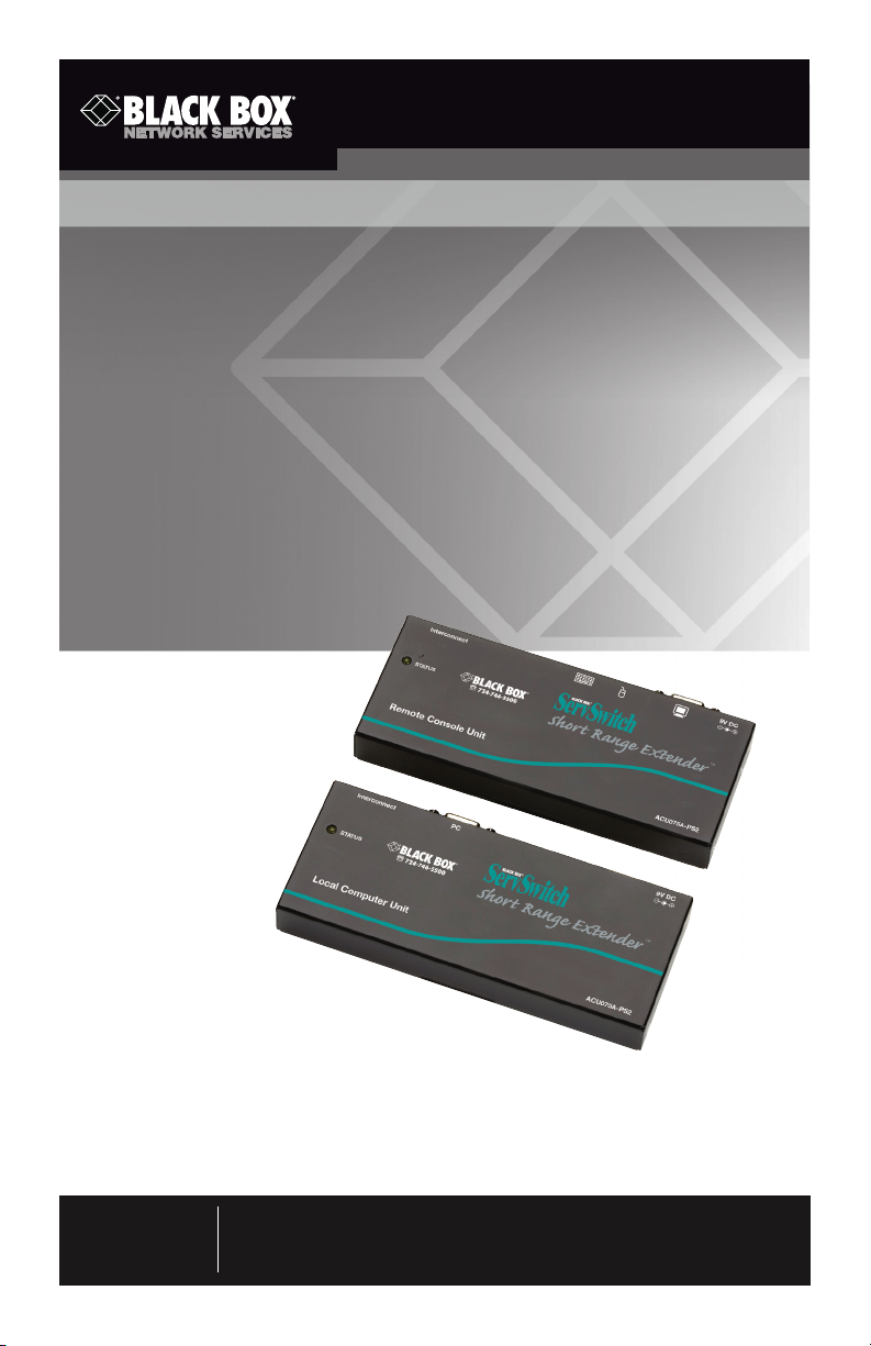
ACU075A-PS2
ACU075A-USB
ServSwitch™ Brand PS/2 and USB KVM Extender Kits
Remotely access a computer located in a secure,
clean or dirty, harsh environment.
Place the keyboard, monitor, and mouse up to 75 feet (23.4 m) away from a computer
or KVM switch.
Use inexpensive Category 5 unshielded twisted-pair cable.
Customer
Support
Information
Order toll-free in the U.S.: Call 877-877-BBOX (outside U.S. call 724-746-5500)
FREE technical support 24 hours a day, 7 days a week: Call 724-746-5500 or fax a
724-746-0746 • Mailing address: Black Box Corporation, 1000 Park Drive, Lawrence,
PA 15055-1018 • Web site: www.blackbox.com • E-mail: [email protected]
Page 3

FCC and NOM Statements
FEDERAL COMMUNICATIONS COMMISSION AND
INDUSTRY CANADA RADIO FREQUENCY INTERFERENCE STATEMENTS
This equipment generates, uses, and can radiate radio-frequency energy,
and if not installed and used properly, that is, in strict accordance with the
manufacturer’s instructions, may cause inter ference to radio communication.
It has been tested and found to comply with the limits for a Class A computing
device in accordance with the specifications in Subpart B of Part 15 of FCC rules,
which are designed to provide reasonable protection against such interference
when the equipment is operated in a commercial environment. Operation of
this equipment in a residential area is likely to cause interference, in which case
the user at his own expense will be required to take whatever measures may be
necessary to correct the interference.
Changes or modifications not expressly approved by the party responsible
for compliance could void the user’s authority to operate the equipment.
This digital apparatus does not exceed the Class A limits for radio noise
emis sion from digital apparatus set out in the Radio Interference Regulation
of Industry Canada.
Le présent appareil numérique n’émet pas de bruits radioélectriques dépassant
les limites applicables aux appareils numériques de la classe A prescrites dans le
Règlement sur le brouillage radioélectrique publié par Industrie Canada.
Normas Oficiales Mexicanas (NOM)
Electrical Safety Statement
INSTRUCCIONES DE SEGURIDAD
1. Todas las instrucciones de seguridad y operación deberán ser leídas antes de que
el aparato eléctrico sea operado.
2. Las instrucciones de seguridad y operación deberán ser guardadas para
referencia futura.
3. Todas las advertencias en el aparato eléctrico y en sus instrucciones de
operación deben ser respetadas.
4. Todas las instrucciones de operación y uso deben ser seguidas.
724-746-5500 | blackbox.com
Page 1
Page 4

ServSwitch Brand PS/2 and USB KVM Extender Kits
5. El aparato eléctrico no deberá ser usado cerca del agua—por ejemplo,
cerca de la tina de baño, lavabo, sótano mojado o cerca de una alberca,
etc..
6. El aparato eléctrico debe ser usado únicamente con carritos o pedestales
que sean recomendados por el fabricante.
7. El aparato eléctrico debe ser montado a la pared o al techo sólo como sea
recomendado por el fabricante.
8. Servicio—El usuario no debe intentar dar servicio al equipo eléctrico más allá
lo descrito en las instrucciones de operación. Todo otro servicio deberá ser
referido a personal de servicio calificado.
9. El aparato eléctrico debe ser situado de tal manera que su posición no
interfiera su uso. La colocación del aparato eléctrico sobre una cama, sofá,
alfombra o superficie similar puede bloquea la ventilación, no se debe
colocar en libreros o gabinetes que impidan el flujo de aire por los orificios
de ventilación.
10. El equipo eléctrico deber ser situado fuera del alcance de fuentes de calor
como radiadores, registros de calor, estufas u otros aparatos (incluyendo
amplificadores) que producen calor.
11. El aparato eléctrico deberá ser connectado a una fuente de poder sólo del
tipo descrito en el instructivo de operación, o como se indique en el
aparato.
12. Precaución debe ser tomada de tal manera que la tierra fisica y la
polarización del equipo no sea eliminada.
13. Los cables de la fuente de poder deben ser guiados de tal manera que no
sean pisados ni pellizcados por objetos colocados sobre o contra ellos,
poniendo particular atención a los contactos y receptáculos donde salen
del aparato.
14. El equipo eléctrico debe ser limpiado únicamente de acuerdo a las
recomendaciones del fabricante.
15. En caso de existir, una antena externa deberá ser localizada lejos de las
lineas de energia.
16. El cable de corriente deberá ser desconectado del cuando el equipo no sea
usado por un largo periodo de tiempo.
Page 2
724-746-5500 | blackbox.com
Page 5

NOM Statement
17. Cuidado debe ser tomado de tal manera que objectos liquidos no sean
derramados sobre la cubierta u orificios de ventilación.
18. Servicio por personal calificado deberá ser provisto cuando:
A: El cable de poder o el contacto ha sido dañado; u
B: Objectos han caído o líquido ha sido derramado dentro del aparato; o
C: El aparato ha sido expuesto a la lluvia; o
D: El aparato parece no operar normalmente o muestra un cambio en su
desempeño; o
E: El aparato ha sido tirado o su cubierta ha sido dañada.
724-746-5500 | blackbox.com
Page 3
Page 6

ServSwitch Brand PS/2 and USB KVM Extender Kits
TRADEMARKS USED IN THIS MANUAL
Black Box and the Double Diamond logo are registered trademarks, and
ServSwitch is a trademark, of BB Technologies, Inc.
PS/2 is a registered trademark of International Business Machines Corporation.
Microsoft and IntelliMouse are registered trademarks of Microsoft Corporation.
Any other trademarks mentioned in this manual are acknowledged to be
the property of the trademark owners.
Page 4
724-746-5500 | blackbox.com
Page 7

Table of Contents
Table of Contents
1. Specifications ................................................................................................ 6
2. Overview................................................................................................................... ... 7
2.1 Introduction ......................................................................................... 7
2.2 Features.... ............................................................................................ 7
2.3 What’s Included ................................................................................... 8
2.4 Remote Console Unit .......................................................................... 8
2.4.1 Front Panel ................................................................................ 8
2.4.2 Top Panel .................................................................................. 8
2.5 Local Computer Unit ............................................................................ 9
2.5.1 Front Panel ................................................................................ 9
2.5.2 Back Panel................................................................................. 9
3. Installation........ .............................................................................................10
4. Configuration ...............................................................................................11
5. Operation......................................................................................................12
5.1 LED Indicators .....................................................................................12
5.2 Hotkeys Control (Console Unit Only) ..................................................12
Appendix A: Troubleshooting ............................................................................15
A.1 Calling Black Box .................................................................................15
A.2 Shipping and Packaging ......................................................................15
724-746-5500 | blackbox.com
Page 5
Page 8

ServSwitch Brand PS/2 and USB KVM Extender Kits
1. Specifications
Resolution: 1280 x 1024 @ 75 feet (23.4 m)
Connectors: ACU075A-USB: Console (Station) Unit: (1) HD15 F, (1) RJ-45,
(2) USB Type A F, (1) barrel connector;
Computer Unit: (1) HDB15 F, (1) RJ-45, (1) barrel connector;
ACU075A-PS2: Console (Station) Unit: (1) HD15 F, (1) RJ-45,
(2) 6-pin mini-DIN, (1) barrel connector;
Computer Unit: (1) HDB15 F, (1) RJ-45, (1) barrel connector
Indicators: ACU075A-USB, ACU075A-PS2: Console (Station) Unit: (1) On LED;
Computer Unit: (1) On LED
Power: External 9-VDC, 800 mA power supply
Size: 0.8"H x 2.6"W x 6.1"D (2 x 6.5 x 15.6 cm)
Weight: Each transmitter or receiver unit: 0.6 lb (0.3 kg)
Page 6
724-746-5500 | blackbox.com
Page 9

Chapter 2: Overview
2. Overview
2.1 Introduction
The KVM Extender consists of a computer unit and a console (station) unit. It
allows you to place a keyboard/monitor/mouse up to 75 feet (23.4 meters) away
from a computer or KVM switch using an inexpensive Category 5 UTP (unshielded
twisted pair) cable. The extender provides an ideal and convenient way to remotely access a computer located in a secure, clean or dirty, harsh environment.
The KVM Extender enables one user to control one computer, remotely. Use it
in factory or construction areas where you want to secure your computer and
valuable data or manage it remotely.
Use the extenders in a PS/2® or USB system. No software or DIP switches are
required, just plug and use. With one Status LED indicator and simple hotkey
commands, you can manage this device easily.
Two models are available. The ACU075A-USB allows one USB console to control
one USB computer via 1-to-2 cable. The ACU075A-PS2 enables one PS/2 console
to control one PS/2 computer via 1-to-3 cable.
2.2 Features
• Connectsthecomputerunitandconsole(station)unitviaCategory5UTP
cable.
• Remotelylocatesthekeyboard,monitor,andmouseupto75feet(23.4m)
from a computer.
• TwomodelsavailabletosupportaUSBorPS/2console.
• Hotkeyadjustsvideocompensationforoptimumsignalqualityforanylengthof
cable within the limit.
• Useslow-cost,readily-availablecable.
• LEDindictatorensuressmoothoperation.
• Locatesthecomputerawayfromyourdeskandworkarea,freeingupvaluable
space.
• Beepsoundconfirmskeycontrol.
®
• SupportscommonmicesuchasMicrosoft
etc.
724-746-5500 | blackbox.com
IntelliMouse® (Pro), Explorer, Optical,
Page 7
Page 10
ServSwitch Brand PS/2 and USB KVM Extender Kits
• CompatiblewithXGA,VGA,andSVGAsystem.
2.3 What’s Included
Your package should include the following items. If anything is missing or
damaged, please contact Black Box Technical Support at 724-746-5500.
• (1)KVMExtenderConsole(Station)Unit
• (1)KVMExtenderComputerUnit
• (1)9-VDC,600-mApoweradapter
• (2)setsoffootpads
• (1)KVMCable2-to-1or3-to-1(EHN70001-0006orEHN9000U-0006)
• Thisuser’smanual
2.4 Remote Console Unit
2.4.1 Front Panel
The front panel of the remote console unit is shown on the manual cover
photo. It has one Status LED.
2.4.2 Top Panel
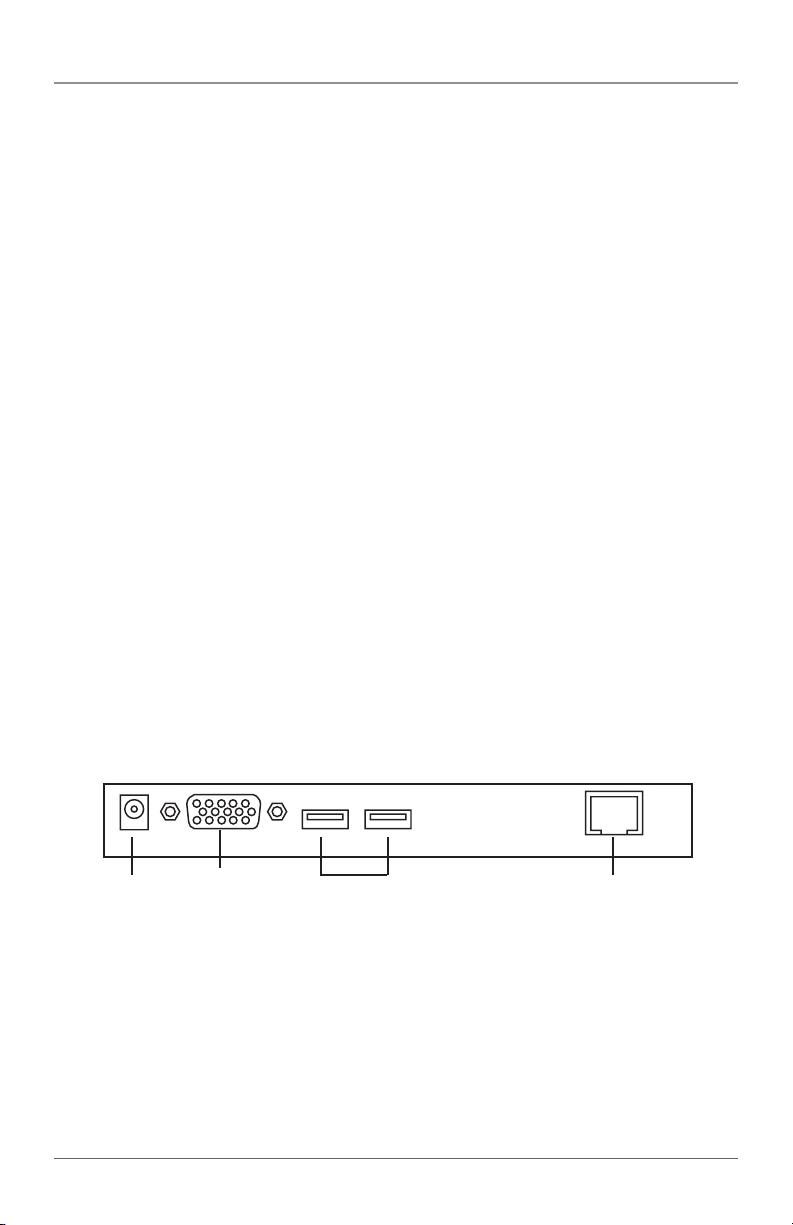
Figures 2-1 and 2-2 show the top panel of the ACU075A-USB and ACU075APS2 remote console units. Tables 2-1 and 2-2 describe their components.
1
Table 2-1. ACU075A-USB remote console unit’s top panel components.
Number Component Description
1 Barrel connector Power
2 HD15 connector Links to monitor
3 (2) USB Type A Links to keyboard and mouse
connectors
4 RJ-45 connector Links to local computer unit
Page 8
2
Figure 2-1. ACU075A-USB remote console unit’s top panel.
3
724-746-5500 | blackbox.com
4
Page 11
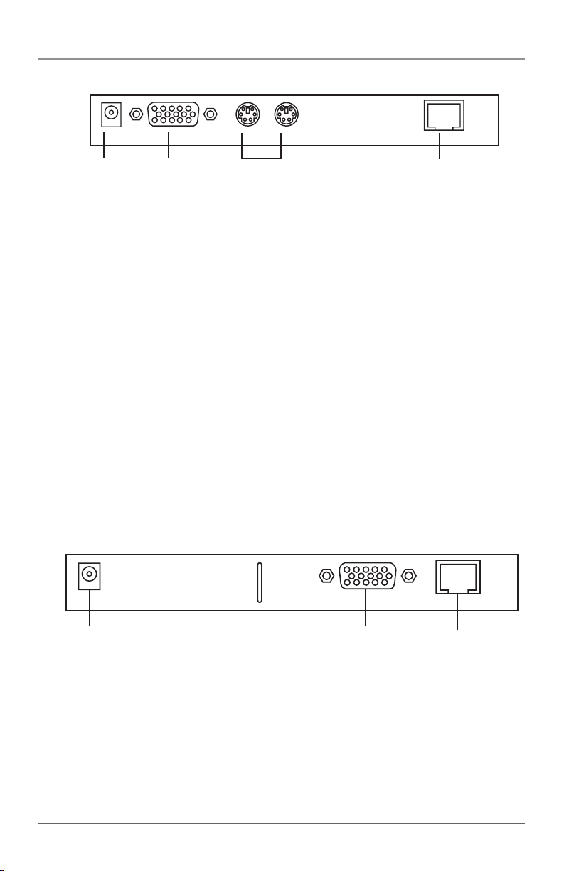
Chapter 2: Overview
1
Table 2-2. ACU075A-PS2 remote console unit’s top panel components.
Number Component Description
1 Barrel connector Power
2 HD15 connector Links to monitor
3 (2) 6-pin mini DIN Links to keyboard and mouse
connectors
4 RJ-45 connector Links to local computer unit
2
Figure 2-2. ACU075A-PS2 remote console unit’s top panel.
3
4
2.5 Local Computer Unit
2.5.1 Front Panel
The front panel of the local computer unit is shown on the manual cover photo.
It has one Status LED.
2.5.2 Back Panel
Figure 2-3 illlustrates the back panel of the ACU075A-USB and ACU075A-PS2
local computer units. Table 2-3 describes its components.
5
Figure 2-3. ACU075A-USB or ACU075A-PS2 local computer unit’s back panel.
Table 2-3. Back panel components.
Number Component Description
5 Barrel connector Power
6 HD15 connector Links to computer’s monitor, keyboard,
and mouse
7 RJ-45 connector Links to remote console
724-746-5500 | blackbox.com
6
7
Page 9
Page 12
ServSwitch Brand PS/2 and USB KVM Extender Kits
3. Installation
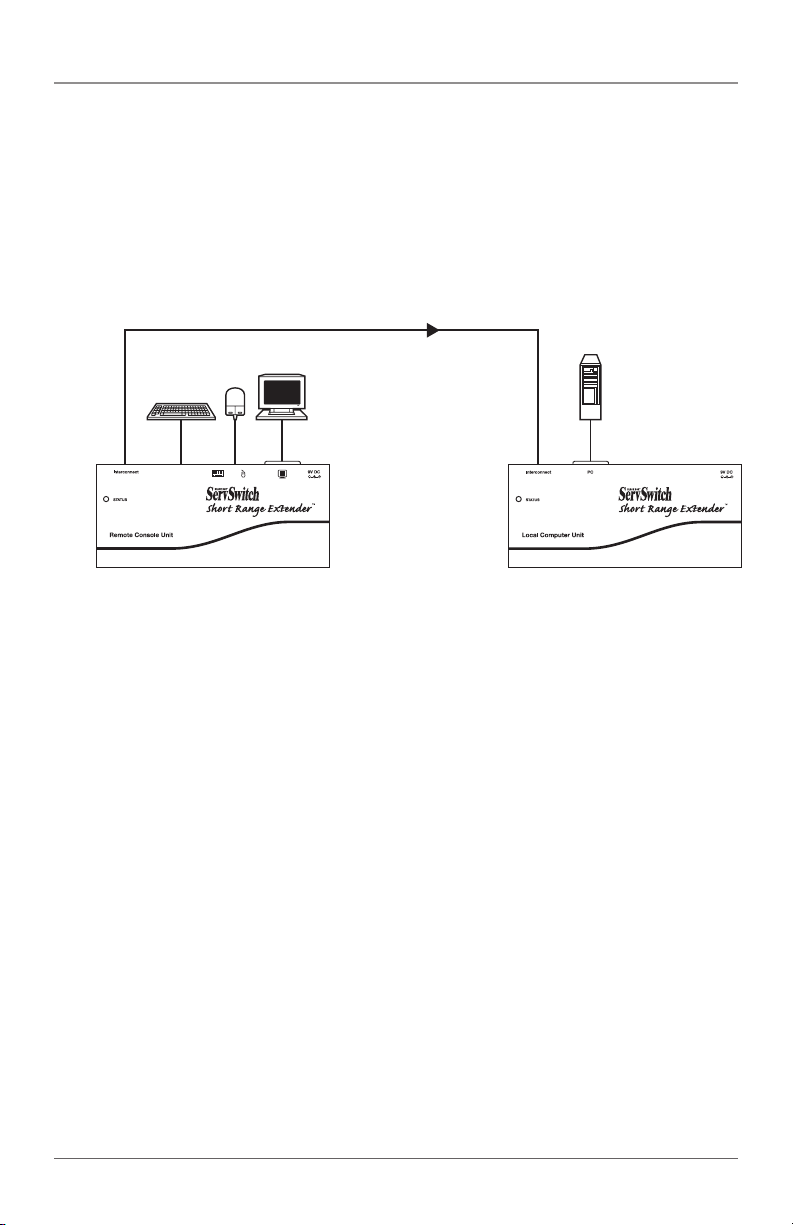
Follow the steps listed below to install the extender.
1. Connect the USB or PS/2 console station unit to the console computer.
2. Attach the USB or PS/2 computer to the extender computer unit.
3. Link the two console and computer units together using ordinary CAT5 cable.
Console
Console
(station) unit
Control direction
Figure 3-1. (1) console to (1) computer configuration.
Computer
Computer
unit
Page 10
724-746-5500 | blackbox.com
Page 13
Chapter 4: Configuration
4. Configuration
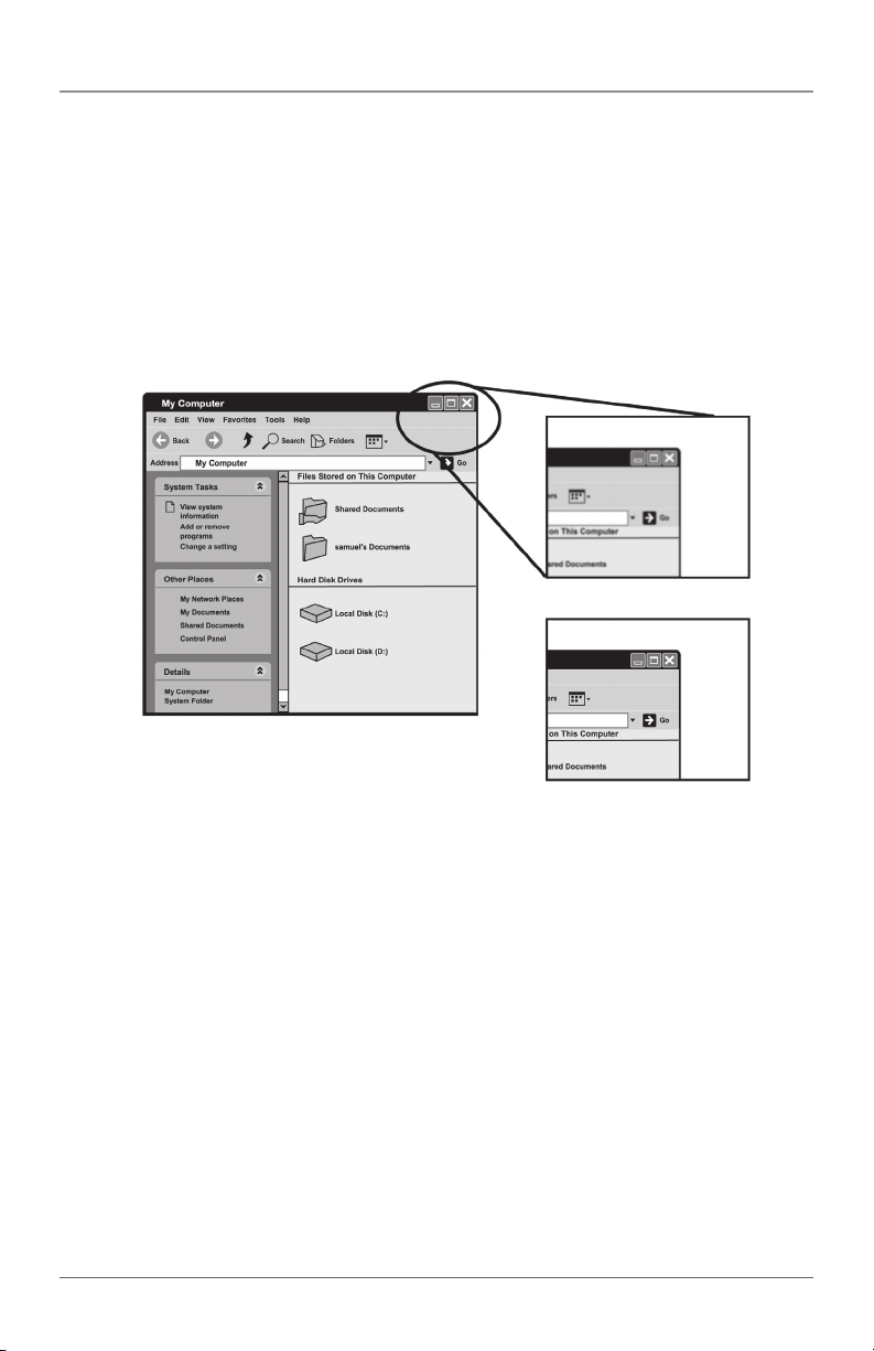
Before operating, adjust the video compensation. Use hotkeys to set the equalization on the remote unit for an optimum video signal and its corresponding
cable length. The CAT5 cable can be one of five different lengths.
First, note the length of the RJ-45 cable you installed in Chapter 3. Then, use
the hotkeys to adjust the video compensation. Press Ctrl twice [Ctrl][Ctrl] followed
by the [Enter] key and the [F11] key. Different beeps indicate how long the
installed cable is. See Section 5.2.
Figure 4-1. Setting the video compensation screen.
NOTE: In standard mode press [Ctrl] [Ctrl], followed by [F11][F11]
In compatibility mode press [Ctrl][Ctrl], then press [Enter] and [F11].
To switch to a different mode, press [Ctrl] +[Ctrl], then press and hold [Alt] and
press [E].
724-746-5500 | blackbox.com
Page 11
Page 14
ServSwitch Brand PS/2 and USB KVM Extender Kits
5. Operation
A keyboard and mouse must be connected to the console (station) unit. The
system then emulates the remote computer so that it can be controlled locally. Or,
you can also control the computer remotely.
5.1 LED Indicators
LEDs on the KVM Extender indicate the linking, communication, and control
between the computer unit and the console (station) unit.
When the console unit’s and the computer unit’s Status LEDs are both ON, the
console unit remotely controls the computer unit.
5.2 Hotkeys Control (Console Units Only)
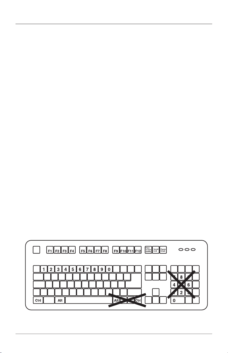
Hotkey command is a short keyboard sequence to select a computer, to activate
computer scan, and so forth. The KVM Extender interprets keystrokes for hotkeys
all the time. A hotkey sequence starts with two left [Ctrl] keystrokes followed by
one or two more keystrokes. A built-in buzzer generates a high-pitched beep for
correct hotkey command, while one short and one long beep are sounded for
incorrect commands. Thus, the bad key commands will not be forwarded to the
selected modes.
There is a unique hotkey command of [Ctrl ] + [Ctrl] + [Alt] + [E] you should
be aware of when the KVM Extenders are connected to other KVM Switches.
To switch to this mode, press left Ctrl twice, hold Alt and press E key (press
both keys simultaneously). You can choose either the control mode of the KVM
Extender or the number of the computer connected to the KVM Switches.
NOTE: Hotkeys do not apply to the ACU075A-USB computer unit or to the
ACU075A-PS2 computer unit.
Figure 5-1. Hotkey locations on a keyboard.
Page 12
724-746-5500 | blackbox.com
Page 15

Chapter 5: Operation
Table 5-1. Hotkey control for console (station) unit.
Console Unit Hotkeys Commands Description
Standard Command Compatibility Mode
(without [Enter] key (with [Enter] key
optional) optional) (add
[Enter] if a KVM
switch is cascaded)
[Ctrl]+[Ctrl]+T Mode selection in sequence
[Ctrl]+[Ctrl]+[F2] [Ctrl]+[Ctrl]+[Enter]+[F2] Toggles console control
between local computer and
remote computer
[Ctrl]+[Ctrl]+[Esc] Escape from hotkey mode
[Ctrl]+[Ctrl]+[Alt+Enter] Cascading status selection
Two beeps: Enables
Compatibility Mode so that
the KVM extender will work
with a KVM switch that also
uses a [Ctrl] hotkey sequence.
One beep: Disables
Compatibility Mode.
[Ctrl]+[Ctrl]+[F4] [Ctrl]+[Ctrl]+[Enter]+[F4] Keyboard speed selection:
Adjusts the keyboard’s type-
matic rate. The KVM extender
generates 1 to 4 beeps corresponding to 6, 12, 20, and 30
characters/sec respectively (for
PS/2 only).
[Ctrl]+[Ctrl]+[F11] [Ctrl]+[Ctrl]+[Enter]+[F11] Video compensation adjust-
ment: Adjusts the video compensation. The KVM extender
generates 1 to 5 beeps corresponding to cable lengths of
0–30, 30–60, 60–90,
90–120, and 120–150 meters,
respectively.
724-746-5500 | blackbox.com
Page 13
Page 16

ServSwitch Brand PS/2 and USB KVM Extender Kits
Table 5-1 (continued). Hotkey control for console (station) unit.
Console Unit Hotkeys Commands Description
Standard Command Compatibility Mode
(without [Enter] key (with [Enter] key
optional) optional) (add
[Enter] if a KVM
switch is cascaded)
[Ctrl]+[Ctrl]+[F12] [Ctrl]+[Ctrl]+[Enter]+[F12] Mouse resynchronized
(for PS/2 only)
NOTE: Special hotkey [Ctrl]+[Ctrl]+[Enter]+[Enter] enables the KVM extender to
link with port E (the 13th port of a KVM switch cascaded) under the
Compatibility Mode. For cascading the KVM switch, the
command is [Ctrl]+[Ctrl]+[Enter]+[Enter]+[Enter].
NOTE: The keyboard speed selection function applies to PS/2 models only.
Page 14
724-746-5500 | blackbox.com
Page 17

Appendix: Troubleshooting
Appendix. Troubleshooting
A.1 Calling Black Box
If you determine that your ServSwitch Brand PS/2 or USB KVM Extender Kit is
malfunctioning, do not attempt to alter or repair the unit. It contains no user-serviceable parts. Contact Black Box Technical Support at 724-746-5500.
Before you do, make a record of the history of the problem. We will be able to
provide more efficient and accurate assistance if you have a complete description,
including:
• thenatureanddurationoftheproblem.
• whentheproblemoccurs.
• thecomponentsinvolvedintheproblem.
• anyparticularapplicationthat,whenused,appearstocreatetheproblemor
make it worse.
A.2 Shipping and Packaging
If you need to transport or ship your ServSwitch Brand PS/2 or USB KVM
Extender Kit:
• Packageitcarefully.Werecommendthatyouusetheoriginalcontainer.
• Ifyouarereturningtheunit,makesureyouincludeeverythingyoureceived
with it. Before you ship for return or repair, contact Black Box to get a Return
Authorization (RA) number.
724-746-5500 | blackbox.com
Page 15
 Loading...