

Page 1

DVI-D CATX SWITCH/SPLITTER
1
Welcome to the CATX DVI-D Family!
Thank you for purchasing a CATX DVI-D Switch! We appreciate your business, and we
think you’ll appreciate the many ways that your CATX DVI-D system will save you money,
time, and effort.
The CATX DVI-D Switch offers three fundamental uses:
• As a Multiplex Repeater: the DVI signals (+optional audio) coming from a signal
source are equalized and distributed on up to 7 equivalent outputs. A control is not
necessary. Distributed display systems can be realized (Digital Signage).
• As an 8-port Crosspoint Switch: each port can be switched optionally as an input or
output. You can, for example, switch and distribute the signals from 3 signal
sources on up to 5 displays (allowing simultaneous presentations on several
displays). Alternatively, signals coming from 7 signal sources can be switched in
turn to a single display. The changeover can be triggered remotely using the serial
interface (RS232) and/or by a push-button at the device.
• As a 7-port KVM Switch: up to 7 Singlehead ports (a “Singlehead” extender system
supports 1x monitor, 1x keyboard, 1x mouse) or up to 3 Dualhead ports (a
Dualhead extender system supports 2x monitor, 1x keyboard, 1x mouse). The
changeover can be triggered remotely using the serial interface (RS232) and/or by a
push-button at the device.
Cascade multiple devices in two stages for all applications to give up to 49/1 connections.
The CATX DVI-D Switch has the advantage that it can be positioned up to 140m away from
both your signal source and display device. This becomes possible by using the proven
CATX DVI-D- Extender technology for the transmission of DVI- Monitor and USBKeyboard and Mouse signals over CATx- cable.
The operation of a CATX DVI-D Switch always requires at least one Local Unit and up to
seven Remote Units from the CATX DVI-D-Extenders range.
Page 2

DVI-D CATX SWITCH/SPLITTER
2
Wherever long distances cause problems for remotely locating and switching a monitor
(keyboard/mouse) signal, e.g. airports, industrial plants, call centres or in distributed
computer centres, the CATX DVI-D Switch is the best solution. Its flexibility allows it to
tackle many tasks.
In addition, there are 4 Media Extenders (DVI + optional audio) and 8 KVM- Extenders
(DVI+USB keyboard mouse + optional audio) available. The transmission of the signals
requires connecting CATx cable.
This manual will tell you all about your new CATX DVI-D Switch, including how to install,
operate and troubleshoot it. For an introduction to the Converter, see Chapter 2.
The Converter product codes covered in this manual are:
ACX4000: 7-port CATX DVI-D Switch
ACS4001A-T: CATX DVI-D- KVM Local Unit, Singlehead
ACS4201A-T: CATX DVI-D- KVM Local Unit, Dualhead
ACS4022A-T: CATX DVI-D- KVM Local Unit, +Audio, Singlehead
ACS4222A-T: CATX DVI-D- KVM Local Unit, +Audio, Dualhead
ACS4001A-R: CATX DVI-D- KVM Remote Unit, Singlehead
ACS4201A-R: CATX DVI-D- KVM Remote Unit, Dualhead
ACS4022A-R: CATX DVI-D- KVM Remote Unit, +Audio, Singlehead
ACS4222A-R: CATX DVI-D- KVM Remote Unit, +Audio, Dualhead
Page 3

DVI-D CATX SWITCH/SPLITTER
3
Copyrights and Trademarks
©2007. All rights reserved. This information may not be reproduced in any manner without
the prior written consent of the manufacturer.
Information in this document is subject to change without notice and the manufacturer shall
not be liable for any direct, indirect, special, incidental or consequential damages in
connection with the use of this material.
All trademark and trade names mentioned in this document are acknowledged to be the
property of their respective owners.
Disclaimer
While every precaution has been taken in the preparation of this manual, the manufacturer
assumes no responsibility for errors or omissions. Neither does the manufacturer assume any
liability for damages resulting from the use of the information contained herein. The
manufacturer reserves the right to change the specifications, functions, or circuitry of the
product without notice.
The manufacturer cannot accept liability for damage due to misuse of the product or due to
any other circumstances outside the manufacturer’s control (whether environmental or
installation related). The manufacturer shall not be responsible for any loss, damage, or injury
arising directly, indirectly, or consequently from the use of this product.
Cautions and Notes
The following symbols are used in this guide:
CAUTION: This indicates an important operating instruction
that should be followed to avoid any potential damage to
hardware or property, loss of data, or personal injury.
NOTE. This indicates important information to help you make the best use of
this product.
Page 4

DVI-D CATX SWITCH/SPLITTER
4
Page 5

SAFETY-PRECAUTIONS AND
INSTALLATION GUIDLINES
5
EUROPEAN UNION DECLARATION OF CONFORMITY
This is to certify that, when installed and used according to the instructions in this
manual, together with the specified cables and the maximum CPU- cable length <3m,
the Units:
List on page 2
are shielded against the generation of radio interferences in accordance with the
application of Council Directive 89/336/EEC as well as these standards:
EN 55022: 1999 Class A
EN 55024: 1999
IEC 61000-4-2: 2001
IEC 61000-4-3: 2001
IEC 61000-4-4: 2001
EN 61000-3-2 2001
EN 61000-3-3 2002
The device was tested in a typical configuration with CPU.
Thursday, September 15
th
, 2007
The management
This equipment has been found to comply with the limits for a Class A digital device,
pursuant to Part 15 of the FCC Rules. These limits are designed to provide reasonable
protection against harmful interference when the equipment is operated in a commercial
environment. This equipment generates, uses, and can radiate radio frequency energy and, if
not installed and used in accordance with the instruction manual, may cause harmful
interference to radio communications. Operation of this equipment in a residential area is
likely to cause harmful interference in which case the user will be required to correct the
interference at his own expense.
Page 6

DVI-D CATX SWITCH/SPLITTER
6
Safety Precautions and Installation Guidelines
To ensure reliable and safe long-term operation, please note the following installation
guidelines:
• Do not use CATx- devices to link between buildings – please use fibre devices.
• Only use in dry, indoor environments.
• If the building has 3-phase AC power, try to ensure that equipment connected to the
Local and Remote Units is on the same phase.
• Try not to route a CATx- link cable alongside power cables.
• The Remote Unit, Local Unit and any power supplies can get warm. Do not locate them
in an enclosed space without any airflow.
• Do not place a power supply directly on top of a unit.
• Do not obscure a unit’s ventilation holes.
To safeguard against personal injury and avoid possible
damage to equipment or property, please observe the
following:
• Only use power supplies originally supplied with the
product or manufacturer-approved replacements. Do not
attempt to dismantle or repair any power supply. Do not
use a power supply if it appears to be defective or has a
damaged case.
• Connect all power supplies to grounded outlets. In each
case, ensure that the ground connection is maintained
from the outlet socket through to the power supply’s AC
power input.
• Do not attempt to modify or repair this product, or make
a connection from the CATx- link interface (RJ45) to any
other products, especially telecommunications or
network equipment.
Page 7

CONTENTS
7
Contents
1. Quick Setup 11
2. Overview 12
2.1 Introduction 12
2.2 Glossary 13
2.3 Example of a CATX DVI-D-Switch System 14
2.4 Features 15
2.5 Product Range 16
2.6 Compatibility 17
Interface Compatibility 17
2.7 How to Use This Guide 18
Connection & Compatibility 18
DDC Information 18
Selecting the moment of switching to the next frame 18
3. Installation 19
3.1 Package Contents 19
3.2 Interconnection Cable Requirements 21
3.3 System Setup 22
3.4 Installation Instructions 25
4. Device Views 26
4.1 CATX DVI-D-Switch for CATx 26
Configuration ‘Multiplex-Repeater’ – 1 Source up to 7 Displays 26
Configuration ‘Multiplex-Repeater’ – 2 Sources / each up to 3 Displays 26
Configuration ‘Multiplex-Repeater’ – 4 Sources on 4 Displays 27
Configuration ‘Crosspoint-Switch’ 1 Input / 7 Outputs 27
Configuration ‘Crosspoint-Switch’ 2 Inputs / 6 Outputs 28
Configuration ‘Crosspoint-Switch’ 3 Inputs / 5 Outputs 28
Configuration ‘Crosspoint-Switch’ 4 Inputs / 4 Outputs 29
Configuration ‘Crosspoint-Switch’ 5 Inputs / 3 Outputs 29
Configuration ‘Crosspoint-Switch’ 6 Inputs / 2 Outputs 30
Configuration ‘Crosspoint-Switch’ 7 Inputs / 1 Output 30
Configuration ‘Singlehead KVM-Switch’ 31
Configuration ‘Dualhead KVM-Sw itch’ 31
4.2 CATX DVI-D- KVM Extender 33
5. Diagnostic 38
5.1 CATX DVI-D-Switch for CATx 38
5.2 CATX DVI-D- KVM Extender 40
Page 8

DVI-D CATX SWITCH/SPLITTER
8
6. Service Setup 41
6.1 CATX DVI-D-Switch for CATx 41
Operating Mode Selection 42
6.2 CATX DVI-D-KVM Extender 44
6.3 Setup at the Local Unit 45
DDC / colour depth 45
Reset of the internal DDC table to default-values 46
Loading the DDC information from the remote monitor 47
Selection of Colour depth 47
6.4 Setup at the Remote Unit 48
Selecting the moment of switching to the next frame 48
7. Operating Modes 49
7.1 Multiplex- Repeater 49
Configuration ‘Multiplex-Repeater’ – 1 Source up to 7 Displays 49
Configuration ‘Multiplex-Repeater’ – 2 Sources, each up to 3 displays 50
Configuration ‘Multiplex-Repeater’ – 4 Sources on 4 Displays 50
Example Applications: 51
Indicator LEDs 53
Meaning of the diagnostic LEDs: 53
Setup 54
Operation 54
By serial interface 54
Control commands 54
7.2 Crosspoint- Switch 55
Configuration ‘Crosspoint-Switch’ 1 Input / 7 Outputs 56
Configuration ‘Crosspoint-Switch’ 2 Inputs / 6 Outputs 56
Configuration ‘Crosspoint-Switch’ 3 Inputs / 5 Outputs 57
Configuration ‘Crosspoint-Switch’ 4 Inputs / 4 Outputs 57
Configuration ‘Crosspoint-Switch’ 5 Inputs / 3 Outputs 58
Configuration ‘Crosspoint-Switch’ 6 Inputs / 2 Outputs 58
Configuration ‘Crosspoint-Switch’ 7 Inputs /1 Output 59
Example Application: 60
Setup 61
Indicator LEDs 62
Meaning of the diagnostic LEDs: 62
Operation 63
a) By push button: 63
b) By serial interface 63
Control commands 64
Examples: 64
7.3 Singlehead KVM- Switch 65
Configuration ‚Singlehead KVM- Switch’ 65
Example Application: 66
Setup 67
Master/Slave function 67
Operating mode after Reset/Power ON 67
Indicator LEDs 68
Meaning of the diagnostic LEDs: 68
Operation 69
a) By push-button: 69
Page 9

CONTENTS
9
b) By serial interface 69
Control commands 70
Examples: 70
c) By the attached keyboard 71
User commands 71
Call of the command mode 72
Instructions within the command mode 73
Examples: 74
7.4 Dualhead KVM- Switch 75
Configuration of ‘Dualhead KVM- Switch’ 75
Example Application: 76
Setup 77
Master/Slave function 77
Operating mode after Reset/Power ON 77
Indicator LEDs 78
Meaning of the diagnostic LEDs: 78
Operation 79
a) By push-button: 79
b) By serial interface 79
Control commands 80
Examples: 80
c) By the attached keyboard 81
User commands 81
Call of the command mode 82
Instructions within the command mode 83
Examples: 84
7.5 Systeminfo 85
Control command 85
Available Information 85
7.6 Restore Factory Defaults 86
8. Troubleshooting 87
Monitor 87
Keyboard 88
Appendix A: Example Applications 90
Appendix B: Rack Mount Options 96
Appendix C: Devices with serial/audio option 100
Serial link: 100
Audio link: 100
Serial Interface - Setup and Operation 100
Serial Interface – Handling Multiple Serial Devices 101
Audio Interface - Setup and Operation 101
Audio Interface – Using a Microphone 101
Appendix D: Protocol for command mode 102
Sequence of data communication 103
Telegrams, global functions 103
Switching functions 104
Glossary: 104
Telegrams, switching functions 104
Page 10

DVI-D CATX SWITCH/SPLITTER
10
Appendix E: Calling Technical Support 105
Appendix F: List of supported USB devices 106
Appendix G: Specifications 107
A CATX DVI-D-Media/KVM Local/ Remote Unit 107
Power Supply 107
Interface (depending on type of device) 107
Maximum Length of Interconnection Cable 107
Type of Interconnection Cable 107
Size and Shipping Weight 108
Environmental 108
B CATX DVI-D- Switch Unit 109
Power Supply 109
Interface 109
Maximum Length of Interconnection Cable 109
Type of Interconnection Cable 109
Size and Shipping Weight 109
Environmental 109
Appendix H: Connectors 110
A CATX DVI-D- Local/ Remote Unit 110
DVI-I connector 110
Special connector, DVI-I alike 111
Serial Interface 113
B CATX DVI-D- Switch Unit 114
Serial Interface 114
C All CATX DVI-D- Devices 115
Power Supply 115
CATx- Interfaces 115
Appendix I: Connection Cable 116
Serial cable to connect the CATX DVI-D- Switch to CPU 116
Cross- Cable 117
Page 11
QUICK SETUP
11
1. Quick Setup
This section briefly describes how to install your CATX DVI-D Switch system. Unless you
are an experienced user, we recommend that you follow the full procedures described in the
rest of this manual.
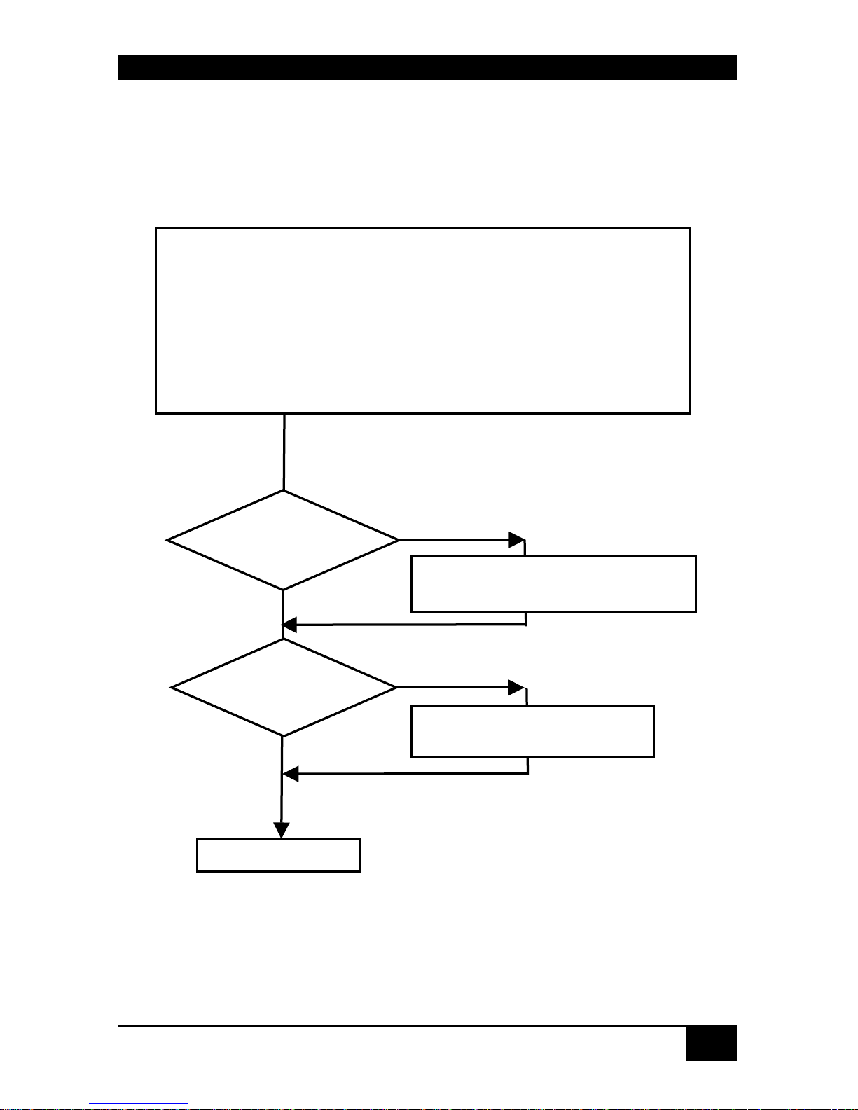
Installation of the system
1. Mark the CATx DVI-D KVM SWITCH with the help of the provided
stickers according to your application
2. Set the DIP-switch according to your application
3. Connect CATx DVI-D KVM Switch to Local unit with CATx- cable(s).
4. Connect CATx DVI-D KVM Switch to Remote unit with CATx- cable(s).
5. Connect the devices to the power supplies.
6. Power up the system.
Done
YES
NO
Link LED
illuminated?
NO
YES
Check p.s.u.’s and connection to
power outlet
Power LED
illuminated?
Check the CATx- cable, and
CATx- connectors
Page 12

DVI-D CATX SWITCH/SPLITTER
12
2. Overview
2.1 Introduction
The CATX DVI-D Switch can be set up in three configurations:
• As a Multiplex Repeater: - the DVI signals (+optional audio) coming from a
signal source are equalized and distributed on up to 7 equivalent outputs. A control
is not necessary. Distributed display systems can be realized (digital signage).
There are three operating modes: 1 link (1 source to 7 screens), 2 links (1 source to
3 screens each) and 4 links (1 source to 1 screen each): a pure length booster.
• As an 8-port Crosspoint Switch: each port can be switched optionally as an input
or output so you can, for example, switch and distribute the signals from 3 signal
sources on up to 5 displays (allowing simultaneous presentations on several
displays). Alternatively, signals coming from 7 signal sources can be switched in
turn to a display. The changeover can be triggered remotely using the serial
interface (RS232) and/or by a push-button at the device.
• As a 7-port KVM Switch: up to 7 Singlehead switches (a “Singlehead” extender
system supports 1x monitor, 1x keyboard, 1x mouse) or up to 3 Dualhead switches
(a Dualhead extender system supports 2x monitor, 1x keyboard, 1x mouse). The
changeover can be triggered remotely using the serial interface (RS232) and/or by a
push-button at the device.
A Multiplex Repeater system comprises a CATX DVI-D Switch and one or more
Local/Remote Units. Optionally, several CATX DVI-D Switches can be cascaded in
maximally two stages (master/slave). The CATX DVI-D Switch and the Local/ Remote Units
are attached by CATx interconnection cables.
The operation of a CATX DVI-D Switch always requires (at least) one Local Unit of a CATX
DVI-D-Extender and up to seven Remote Units of CATX DVI-D-Extenders.
Page 13
OVERVIEW
13
2.2 Glossary
The following terms are used in this guide:
CATx
Any Category 5, 5e, 6 or higher cable, solid wires type AWG24.
KVM
Keyboard, Video and Mouse.
Console
Keyboard, Mouse and Monitor
Dual Access
A system allowing connection of Local and Remote User Consoles.
Singlehead
An extender system that supports one Monitor + Keyboard/ Mouse
Dualhead
An extender system that supports two Monitors + Keyboard/ Mouse
DVI
Digital Video standard, installed by Digital Display Working Group
(www.ddwg.org
) R, G, B, CLOCK in a data stream with up to
3x1,6 Gbit/sec. Signals are TMDS Level.
PSU
The desktop power supply connected to the CATX DVI-D-Switch or
to the Local/ Remote Unit.
HID
Human Interface Devices are units, which are used for human access
to the CPU: keyboard and mouse, touch-screen, light pen, fingerprint
sensor, graphic tablets etc.
Page 14
DVI-D CATX SWITCH/SPLITTER
14
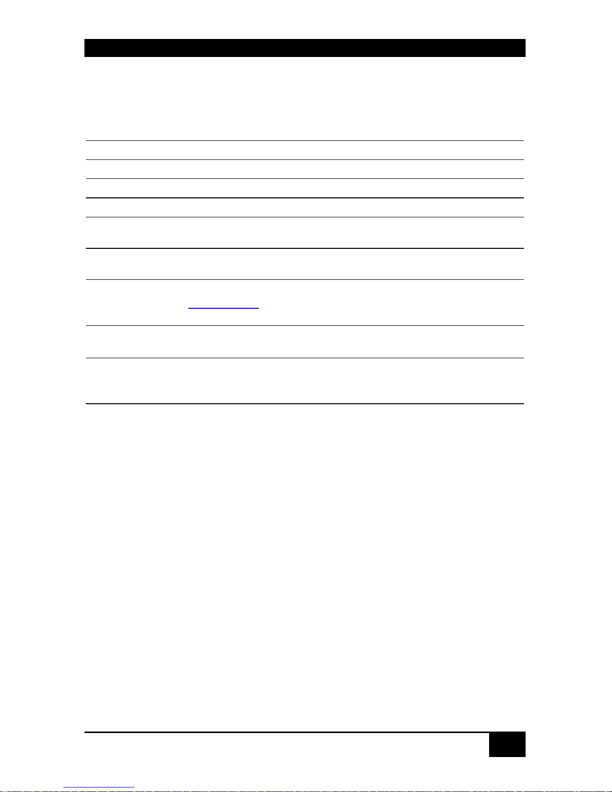
2.3 Example of a CATX DVI-D-Switch System
Example application for a CATX DVI-D Switch System
(Multiplex-Repeater or Crosspoint-Switch)
Up to 7 remote monitors and audio outputs
CPU with DVI graphic card
and audio output
CATx DVI-D-KVM-Extende
r
(Local Unit)
Local monitor
CATx DVI-D KVM - Switch
CATx DVI-D-KVM - Extender- (Remote Units)
Page 15

OVERVIEW
15
2.4 Features
All members of the CATX DVI-D Switch Series offer the following features:
• Support for DVI-D Graphic cards (all devices)
• Support for USB-Keyboard and USB-Mouse (KVM-Extender)
CATX DVI-D- KVM devices with USB- connectors support the extension of
keyboard and mouse ONLY; use with other HID devices (Human Interface
Device) such as touch screens, graphics tablets, barcode readers or similar
may be successful – but there is no guarantee for this! The CATX DVI-DKVM is NOT suitable for use with other USB- devices such as scanners,
web- cams, data sticks etc.
CATX DVI-D- KVM devices support only two devices simultaneously –
keyboard and mouse or keyboard and touch-screen, etc. but not e.g.
keyboard, mouse and touch-screen simultaneously. You can extend a USB
hub but this does not raise the number of supported devices.
• Maximum length of interconnection cable from a Local Unit to a CATX DVI-D-Switch,
between two CATX DVI-D-Switches or from a CATX DVI-D-Switch to a Remote
Unit).
• 140m (400ft) with CATx- cable
• Maximum Resolution (DVI):
• 1920x1200@60Hz
• Supports:
• 18 Bit- (= 256K colours) or 21 Bit- (=16M colours)
• Status indicator LEDs for Power and Link on each device.
• Small footprint chassis.
• Rack mount options available.
• International power supplies included.
• Optional support for audio (+serial/RS232).
Page 16

DVI-D CATX SWITCH/SPLITTER
16
2.5 Product Range
There are 13 products in the range and various upgrade kits:
CATX DVI-D-Switch
ACX4000 (CATx) CATX DVI-D Switch for CATx
KVM- Extender Local Units
ACS4001A-T CATX DVI-D-KVM Local Unit, Singlehead
ACS4201A-T CATX DVI-D-KVM Local Unit, Dualhead
ACS4022A-T CATX DVI-D-KVM Local Unit, +Audio, Singlehead
ACS4222A-T CATX DVI-D-KVM Local Unit, +Audio, Dualhead
KVM- Extender Remote Units
ACS4001A-R CATX DVI-D-KVM Remote Unit, Singlehead
ACS4201A-R CATX DVI-D-KVM Remote Unit, Dualhead
ACS4022A-R CATX DVI-D-KVM Remote Unit, +Audio, Singlehead
ACS4222A-R CATX DVI-D-KVM Remote Unit, +Audio, Dualhead
Upgrade Kits
ACS1009A-RMK 19”/1HE rack mount kit to mount up to 4 Singlehead
devices
ACS2209A-RMK 19”/1HE rack mount kit to mount up to 4 Dualhead
devices/ CATX DVI-D switch devices
ACS2209A-PS
19“mountable power supply for up to three CATX DVI-Ddevices.
Page 17

OVERVIEW
17
2.6 Compatibility
Interface Compatibility
• Digital Video (DVI-D): Digital Video standard, installed by Digital Display Working
Group (www.ddwg.org
) R, G, B, CLOCK in a data stream with up to 3x 1,6 Gbit/sec.
Signals are TMDS Level.
• USB Keyboard: Compatible with all standard keyboards. Certain keyboards with
enhanced features may also be supported with custom firmware. Keyboards with built-in
hub are also supported – but there are never more than two HID devices supported.
• USB Mouse: Compatible with all standard 2-button, 3-button and wheel mice.
The CATX DVI-D- KVM devices with USB-connectors support the
extension of keyboard and mouse ONLY; use with other HID devices
(Human Interface Device) such as touch screens, graphics tablets, barcode
readers or similar may be successful – but there is no guarantee for this!
The CATX DVI-D- KVM is NOT suitable for use with other USB- devices
such as scanners, web- cams, data sticks etc.
The CATX DVI-D- KVM support only two devices simultaneously –
keyboard and mouse or keyboard and touch-screen, etc. but not e.g.
keyboard, mouse and touch-screen simultaneously. You can extend a USB
hub but this does not raise the number of supported devices.
Page 18

DVI-D CATX SWITCH/SPLITTER
18
2.7 How to Use This Guide
This guide describes the installation and configuration of the CATX DVI-D Switch. Although
the connection and operation of the system is relatively straightforward, you should consider
the following before getting started:
Connection & Compatibility
The individual CATX DVI-D Switch components consist of:
• CATX DVI-D Switch for CATx: includes the device and power supply.
• CATX DVI-D- KVM Local Unit: includes the device, power supply and all the cable
required to connect the CATX DVI-D- KVM/ Media Local Unit to your CPU/ Signal
source.
• CATX DVI-D- KVM Remote Unit: includes the device and power supply
Please see also Package Contents (Page 19).
For information about connection and installation, see page 21.
DDC Information
Normally it is not necessary to make any adjustments to the CATX DVI-D- KVM/ Media
device. However, in some circumstances, it may be necessary to redefine the source of DDC
information for the CPU. By default, the CATX DVI-D- KVM/ Media uses its own internal
DDC table. If this setting does not satisfy your requirements, the DDC table can either be
switched to the locally attached screen or can be downloaded from the remotely located
screen and stored in the internal DDC table.
To modify the DDC-Setup, see Setup at the Local Unit (Page 45).
Selecting the moment of switching to the next frame
The transmission of screen data is not synchronous to the screen changes of the graphic card.
Normally, the transmission is terminated during the display of a frame on the screen (at the
remote unit). If the device switches to the new frame during the displaying period of the old
frame (somewhere on the screen), it is possible that you will see horizontal screen breaks at
the moment of switching (default). On the other hand, if the device idles until the actual
frame is displayed completely (until VSYNC) then the number of frames per second
transmitted reduces.
To modify the switching behaviour, see Setup at the Remote Unit (Page 48).
Page 19

INSTALLATION
19
3. Installation
For first-time users, we recommend that you carry out a test placement, confined to a single
room, before commencing full installation. This will allow you to identify and solve any
cabling problems and experiment with the CATX DVI-D System more conveniently.
3.1 Package Contents
You should receive the following items in your CATX DVI-D Switch for CATx package:
• CATX DVI-D Switch
• 1x 5V DC universal power supply for the CATX DVI-D Switch
• 1x serial cable RJ45 / DB9 Female (for switching purpose)
• 1x German type power cord
• 1x sheet of product stickers
• User manual (Quick Setup)
The following parts should be in your CATX DVI-D- KVM Local Unit package:
• CATX DVI-D- KVM Local Unit
• 1x 5V DC universal power supply for the CATX DVI-D-KVM Local Unit
• 1x German type power cord
• DVI-I (1.8m) video cable (DVI-I dual link male-to-male)
• CATx- cross cable (1m)
• CATx- coupler – shielded
• User manual (Quick Setup)
Additionally with the Dualhead devices:
• DVI-I (1.8m) video cable (DVI-I dual link male-to-male)
• CATx- cross cable (1m)
• CATx- coupler - shielded
Page 20

DVI-D CATX SWITCH/SPLITTER
20
Additionally with the CATX DVI-D-KVM devices:
• USB (1.8m) cable (USB type A to type B)
Additionally with the CATX DVI-D-KVM devices +audio:
• Serial cable 1.8m (Serial DB9-male/female)
• 2 audio cables 1.8m
The following parts should be in your CATX DVI-D- KVM Remote Unit package:
• CATX DVI-D- KVM Remote Unit
• 1x 5V DC universal power supply for the CATX DVI-D- KVM Remote Unit
• 1x German type power cord
• CATx- Cross cable (1m)
• CATx- coupler - shielded
• User manual (Quick Setup)
Additionally with the Dualhead devices:
• CATx- Cross cable (1m)
• CATx- coupler - shielded
If anything is missing, please contact Technical Support (see Appendix E: Calling
Technical Support
.
Page 21

INSTALLATION
21
3.2 Interconnection Cable Requirements
To connect the CATX DVI-D- KVM Local Unit to your CPU/signal source you will need
(Please ensure that the connection is tension-free!):
DVI: Connect the supplied DVI-cable 1.8m (DVI-I male to DVI-I male) to your CPU
(KVM- Switch, DVI- signal source, etc.).
USB: Connect the supplied USB- cable 1.8m (USB Type A to USB Type B) to your CPU
(KVM- Switch, DVI- signal source, etc.).
To connect the CATX DVI-D- KVM Local Unit with serial/audio you will additionally need
(Please ensure that the connection is tension-free!):
Serial cable: Connect the supplied serial cable to your CPU/signal source.
Audio cable: Connect the supplied audio cable to your CPU.
CATx- cable: Recommended cable: S/UTP (Cat5) according EIA/TIA 56A, TSB 36 or
Digital STP 17-03170. Four pairs AWG 24. Wiring according EIA/TIA 568A (10BaseT). Use
of cables from a higher category (Cat5e, Cat6, Cat7) is possible.
The use of unshielded CATx- cable is possible; because of the higher electromagnetic
noise/sensitivity, the device class may not be reached.
You may use flexible cables (patch cable) type AWG26/8 but because of the
higher loss of the stranded cables, the maximum extension distance is
reduced to approximately half the value of solid cables.
A point-to-point connection is required. You may use one or more patch
panels in the line. Do not connect the CATx- link interface (RJ45) to any
other products, especially telecommunications or network equipment.
For the connection of the Local Unit to the CATX DVI-D
Switch and Remote Unit to the CATX DVI-D Switch you will
need the supplied cross cables! A direct connection of
EIA/TIA wiring is NOT possible!
Power Supply: Connect the supplied 5V/DC power supplies to the Plug terminal on the rear
of CATX DVI-D- Local Unit, CATX DVI-D Switch or CATX DVI-D- Remote Unit.
Page 22

DVI-D CATX SWITCH/SPLITTER
22
3.3 System Setup
To install your CATX DVI-D Switch system:
1. Switch off all devices.
2. Connect your keyboard, monitor(s) and mouse to the Remote Unit (depending on device
type).
3. Connect the CPU/signal source to the Local Unit using the supplied cable(s).
4. Take the CATX DVI-D switch from the packing and also the sheet with the product
stickers.
5. According to your application, peel the corresponding sticker from the sheet and stick it
on the top panel:
6. Use the associated stickers to label the interface ports:
Page 23

INSTALLATION
23
7. Set the DIP-switches to the positions which correspond to your desired application.
Information for the DIP switch set-up can be found under Operating Mode Selection
8. on page 42.
9. Attach the connection cables (CATx- cable) between the CATX DVI-D switch and
Local Unit and between the CATX DVI-D switch and Remote Unit. Use for this either
the provided crossed CATx- cable or insert the provided crossed cable with the help of
the provided CATx- coupler before/after your CATx- wiring.
For the connection of the Local Unit to the CATX DVI-D
Switch and Remote Unit to the CATX DVI-D Switch you will
need the supplied cross cables! A direct connection of
EIA/TIA wiring is NOT possible!
Connection options:
Page 24

DVI-D CATX SWITCH/SPLITTER
24
10. Depending upon your application, it may be necessary to make a connection to a
controller over the serial interface. Attach the provided RJ45 to DSUB 9-pin cable at the
socket of the serial interface and connect it with your controller. More information for
control through the serial interface can be found on pages Fehler! Textmarke nicht
definiert., Fehler! Textmarke nicht definiert. or Fehler! Textmarke nicht definiert.
11. Connect the 5V power supplies to the units.
Only use the power supply originally supplied with this
equipment or a manufacturer-approved replacement.
12. For a dual access system, connect the monitor for the local console to the appropriate
port on the Local Unit. The port may also be used to feed into a KVM switch.
To attach a local (USB-) keyboard/mouse, please use additional USB port(s) at your
CPU or use a USB hub between the CPU and Local Unit’s USB- connector.
13. Power up the system.
Page 25

INSTALLATION
25
3.4 Installation Instructions
Please ensure that the CATX DVI-D-Switch has sufficient ventilation space by ensuring the
following distances between the unit and other devices and/or mounting parts:
In 19“ rack cabinets: the position closely right and left from the CATX DVI-D-Switch must
kept free!
The CATX DVI-D Switch, its extenders and power supplies
may become warm. Do not install the unit in closed areas
without adequate ventilation.
Never place the power supplies on top of the devices.
Ensure that the existing ventilation openings on the device
are free at all times.
Page 26
DVI-D CATX SWITCH/SPLITTER
26
4. Device Views
4.1 CATX DVI-D-Switch for CATx
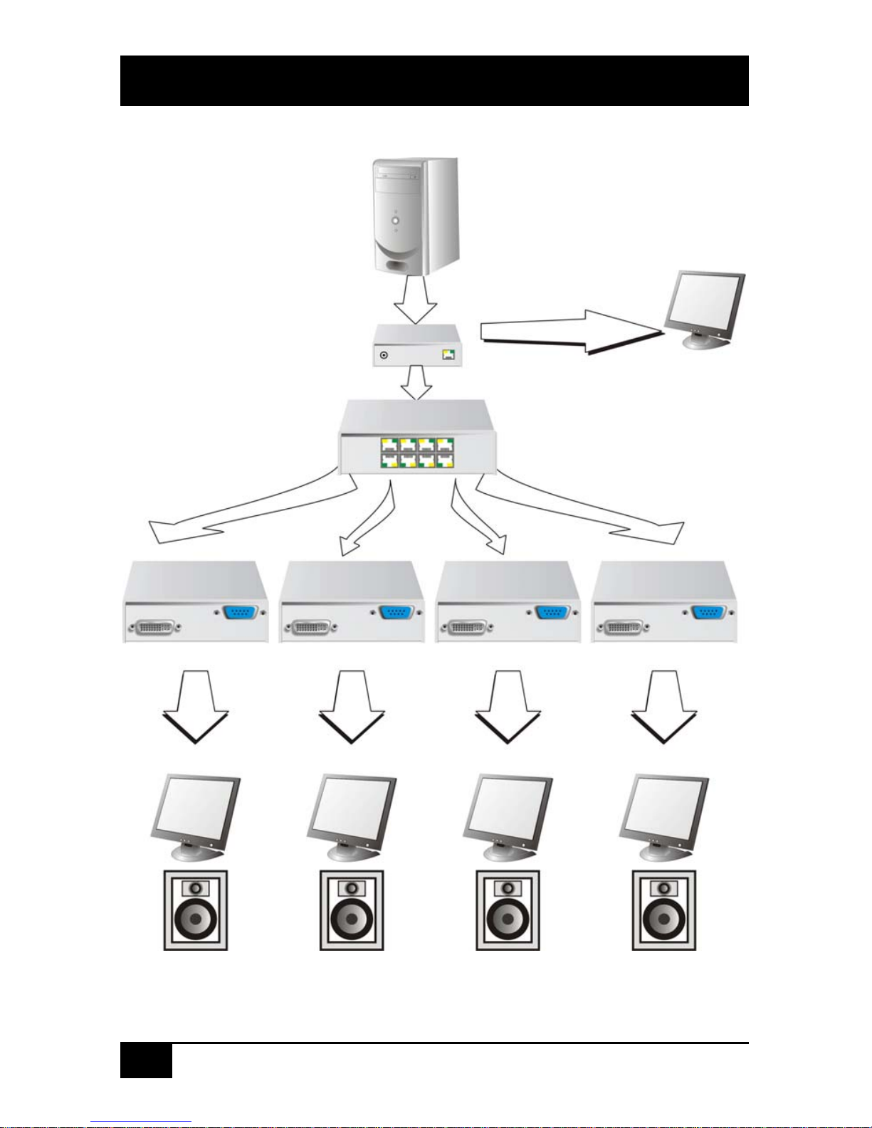
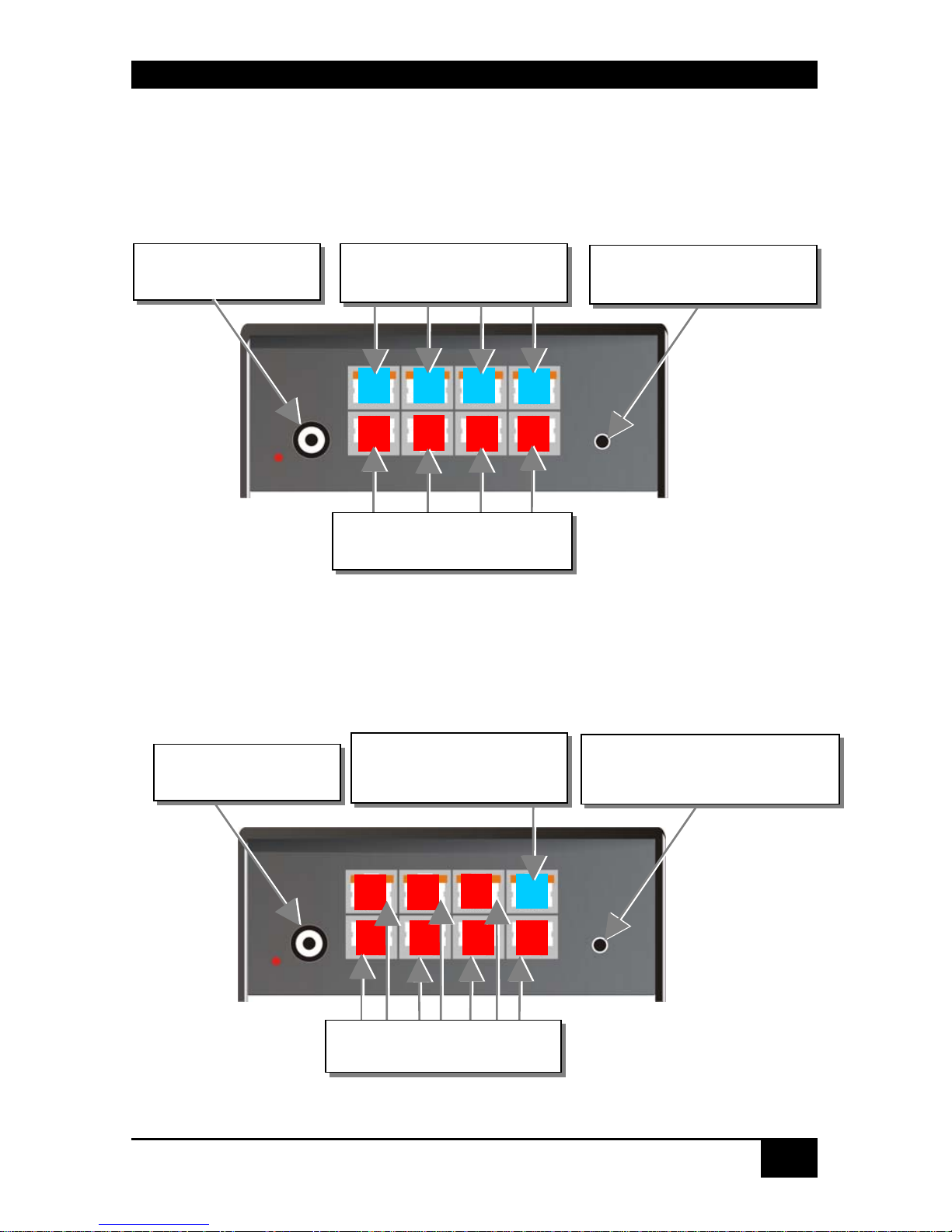
Configuration ‘Multiplex-Repeater’ – 1 Source up to 7 Displays
CATX DVI-D Switch – as 1to7 Multiplex - Repeater
Configuration ‘Multiplex-Repeater’ – 2 Sources / each up to 3
Displays
Connect to the
DRACO™-Media
Remote Units
Push-button, no function
in this operating mode
Push-button, no
function in this
operating mode
R L
R
RRR
R
R
Connect to the
DRACO™-Media
Local Unit
Connect to the
DRACO™-Media
Remote Units
Connect to 5V power
supply
Connect to 5V power
supply
Connect to the CATx DVI-D-
KVM Remote Units A
Connect to the CATx DVI-
D-KVM Local Unit A
Connect to the CATx DVI-D-
KVM - Remote Units B
Connect to the CATx DVI-
D-KVM Local Unit B
Page 27
DEVICE VIEWS
27
CATX DVI-D Switch – as 2x(2to3) Mul tip l ex- Repeater
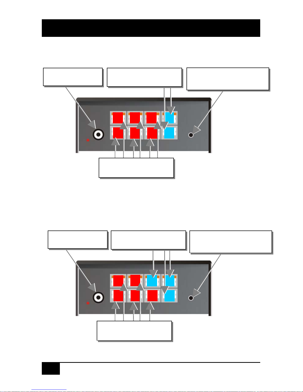
Configuration ‘Multiplex-Repeater’ – 4 Sources on 4 Displays
CATX DVI-D Switch – as 4x 1to4 Multipl ex- Re pea ter
Configuration ‘Crosspoint-Switch’ 1 Input / 7 Outputs
CATX DVI-D Switch – as Crosspoint-Sw itch 1x7
Connect to 5V power
supply
Push-button, no function in
this operating mode
LD
Connect to the CATx DVI-
D-KVM Local Units
Connect to the CATx DVI-D-
KVM Remote Units
Connect to the CATx DVI-D-
KVM Remote Units
Push-button; for the
sequential selection of pre-
programmed configurations
Connect to 5V power
supply
Connect to the CATx DVI-
D-KVM Local Unit
Page 28
DVI-D CATX SWITCH/SPLITTER
28
Configuration ‘Crosspoint-Switch’ 2 Inputs / 6 Outputs
CATX DVI-D Switch – as Crosspoint-Sw itch 2x6
Configuration ‘Crosspoint-Switch’ 3 Inputs / 5 Outputs
CATX DVI-D Switch – as Crosspoint-Sw itch 3x5
Push-button; for the
sequential selection of pre-
programmed configurations
Connect to 5V power
supply
Connect to the CATx DVI-D-
KVM Local Units
Connect to the CATx DVI-D-
KVM Remote Units
Connect to the CATx DVI-D-
KVM Remote Units
Push-button; for the
sequential selection of pre-
programmed configurations
Connect to 5V power
supply
Connect to the CATx DVI-D-
KVM Local Units
Page 29

DEVICE VIEWS
29
Configuration ‘Crosspoint-Switch’ 4 Inputs / 4 Outputs
CATX DVI-D Switch – as Crosspoint-Sw itch 4x4
Configuration ‘Crosspoint-Switch’ 5 Inputs / 3 Outputs
CATX DVI-D Switch – as Crosspoint-Sw itch 5x3
Pushbutton; for the sequential
selection of pre-programmed
configurations
Connect to 5V power
supply
Pushbutton; for the sequential
selection of pre-programmed
configurations
Connect to 5V power
supply
Connect to the CATx DVI-D-
KVM Local Units
Connect to the CATx DVI-D-
KVM Remote Units
Connect to the CATx DVI-D-
KVM Remote Units
Connect to the CATx DVI-D-
KVM Local Units
Page 30

DVI-D CATX SWITCH/SPLITTER
30
Configuration ‘Crosspoint-Switch’ 6 Inputs / 2 Outputs
CATX DVI-D Switch – as Crosspoint-Sw itch 6x2
Configuration ‘Crosspoint-Switch’ 7 Inputs / 1 Output
CATX DVI-D Switch – as Crosspoint-Sw itch 1x7
Connect to 5V power
supply
Pushbutton; for the sequential
selection of pre-programmed
configurations
Connect to 5V power
supply
Connect to the CATx DVI-D-
KVM Local Units
Connect to the CATx DVI-D-
KVM Remote Units
Connect to the CATx DVI-D-
KVM Remote Unit
Connect to the CATx DVI-D-
KVM Local Units
Push-button; for the
sequential selection of pre-
programmed configurations
Page 31

DEVICE VIEWS
31
Configuration ‘Singlehead KVM-Switch’
CATX DVI-D Switch – as Singlehead KVM-Switch
Configuration ‘Dualhead KVM-Switch’
CATX DVI-D Switch – as Dualhead KVM -Sw i tch
Push-button; for the
sequential selection of
the connected CPUs
Connect to the CATx DVI-D-
KVM Local Units (CPU) –
Video 1 + K/M
Connect to the CATx DVI-D-
KVM Remote Units
(Console) – Video 1 + K/M
Connect to 5V power
supply
Connect to the CATx DVI-D-
KVM Local Units (CPU)
Push-button; for the
sequential selection of the
connected PCs
Connect to the CATx DVI-DKVM Remote Unit (Console)
Connect to the CATx DVI-D-
KVM Local Units (CPU)
LA2
LB1
LA1
LB2
RB
R
A
LB3
LA3
Connect to 5V power
supply
Connect to the CATx DVI-D-
KVM Local Units (Console) –
Video 2 + K/M
Connect to the CATx DVI-D-
KVM Local Units (CPU) –
Video 2 + K/M
Page 32

DVI-D CATX SWITCH/SPLITTER
32
CATX DVI-D Switch rear view
Serial Interface
(RS232)
Operating Mode
(DIP switch)
Page 33

DEVICE VIEWS
33
4.2 CATX DVI-D- KVM Extender
CATX DVI-D- KVM Local Unit
CATX DVI-D- KVM Remote Unit
CATX DVI-D- KVM Local/ Remote Unit – rear view
Connect to 5V power
supply
Remote keyboard/
mouse port
To CPU:
DVI- graphic card
Connect to local
DVI- monitor
INTERCONNECT – carries video
and data signals – connect to Local/
Remote Unit with CATx- cable
Remote DVI- monitor port–
Connect to remote console
monitor
Connect to CPU:
USB
Page 34

DVI-D CATX SWITCH/SPLITTER
34
CATX DVI-D- KVM Local Unit with audio
CATX DVI-D- KVM Remote Unit with Audio
Audio In
To CPU: Serial
To CPU: DVI
Connect to CPU:
USB
Audio Out
Serial Out
Connect to local
DVI- monitor
Remote DVI- monitor port–
Connect to remote console
monitor
Remote keyboard/
mouse port
Page 35

DEVICE VIEWS
35
CATX DVI-D- KVM Dualhead Local Unit
CATX DVI-D- KVM Dualhead Rem ote Unit
Connect to CPU:
USB
Connect to CPU:
2
nd
DVI- graphic card
2
n
d
local DVI- monitor port- Connect to
local console 2
nd
monitor
Connect to CPU:
1
st
DVI- graphic card
Local DVI- monitor
port- Connect to local
console monitor
2
n
d
remote DVI- monitor
port- Connect to remote
console 2
nd
monitor
1
s
t
remote DVI-
monitor port– connect
to remote console 1
st
monitor
Remote keyboard/
mouse port
Page 36

DVI-D CATX SWITCH/SPLITTER
36
CATX DVI-D- KVM-Dualhead Local Unit with audio
Audio Out
Serial Out
Remote keyboard/
mouse port
2
n
d
remote DVI- monitor
port- Connect to remote
console 2
nd
monitor
1
s
t
remote DVI- monitor
port– Connect to remote
console 1
st
monitor
2
n
d
local DVI- monitor
port- Connect to local
console 2
nd
monitor
Connect to CPU:
DVI- cable set (2
nd
DVI-
graphic card, audio, serial)
Connect to CPU:
USB
Connect to CPU:
1
st
DVI- graphic card
Local DVI- monitor
port- Connect to local
console monitor
Page 37

DEVICE VIEWS
37
CATX DVI-D- KVM Dualhead Rem ote Unit wi th audio
CATX DVI-D- KVM Local/ Remote Unit with audio – rear view
CATX DVI-D- KVM Dualhead, Local/ Remote Unit, with optional audio – rear
view
Connect to 5V power
supply
Connect to 5V power
supply
INTERCONNECT – carries 2
n
d
video –
Connect to Local/ Remote Unit with
CATx- cable
INTERCONNECT – carries 1
s
t
video
and data signals – Connect to Local/
Remote Unit with CATx- cable
INTERCONNECT – carries video and
data signals – Connect to Local/
Remote Unit with CATx- cable
Page 38

DVI-D CATX SWITCH/SPLITTER
38
5. Diagnostic
5.1 CATX DVI-D-Switch for CATx
Each CATX DVI-D SWITCH is fitted with two indicator LEDs: Power and Link Status: The
Power LED is next to the Power socket. The Link Status LEDs are at the upper CATx-
connectors in the left and right upper corner. The LEDs in the left corners show the status for
the lower CATx- connectors, the right LEDs for the upper CATx- connectors.
The location of the LEDs is shown below:
Diagnostic- LEDs at CATX DVI-D-Switch for CATx
LED Appearance Diagnostics
Power LED
(Red LED)
Off
On
Device not ready
Device ready
Link Status
(Orange LED)
Off
Orange On
Orange Blinking
Green On
Green blinking
No transmission over the CATx- cable
attached local/remote unit is disconnected,
switched off or a broken interconnect cable
Connection through CATx cable is OK
Actual CPU selected by push button (only type
KVM- Switch)
active path (only type KVM- Switch)
the active path has no connection through the trunk
cable (only type KVM- Switch)
Diagnostic LED
Power
Diagnostic LED
Link Status
Lower connector
Diagnostic LED
Link Status
Upper connector
Page 39

DIAGNOSTIC
39
Page 40

DVI-D CATX SWITCH/SPLITTER
40
5.2 CATX DVI-D- KVM Extender
Each CATX DVI-D- Extender is fitted with four indicator LEDs: Power, Video OK, Data
Error, Link Status: The Power LEDs are next to the power socket.
The location of the LEDs is shown below:
Diagnostic- LEDs at CATX DVI-D- KVM Extender
LED Appearance Diagnostics
Power LED
(Red LED)
Off
On
Device not ready
Device ready
Video Okay
(Green LED)
Off
On
No or invalid video signal detected
Device ready
Link Status
(Green LED)
blinking
On
No CATx- connection
Device ready
Data Error
(Green LED)
Off
blinking / On
Device ready
Errors through data transmission over CATx- cable
(cable too long, too high attenuation or too much
EMI interferences)
Diagnostic LED
Power
Diagnostic LED
Video OK
Diagnostic LED
Data Error
Diagnostic LED
Link Status
Page 41

SERVICE SETUP
41
6. Service Setup
6.1 CATX DVI-D-Switch for CATx
Normally, it is only necessary to make adjustments during installation.
In order to make these adjustments, you do not have to open the CATX DVI-D Switch. All
settings can be made from the outside using the Operating Mode Selector (DIP switch).
By selecting a new operating mode, the allocation of inputs
and outputs may be changed. In doing so, it is possible to
interconnect two transmitters: this may damage the
connected equipment.
The location of the operating mode selector (DIP switch) is shown below:
For the selection of a new operating mode:
1. Switch off the CATX DVI-D-Switch.
2. Select a new operating mode according to following table.
By selecting a new operating mode, the allocation of inputs
and outputs may be changed. In doing so, it is possible to
interconnect two transmitters: this may damage the
connected equipment.
3. Power up the device.
Operating Mode
Selector
Page 42

DVI-D CATX SWITCH/SPLITTER
42
Operating Mode Selection
Operating Mode Selector
Operating Mode
Selector
Operating Mode
Multiplex- Repeater: The signal(s) coming from the Local Unit is
(are) equalized (and distributed) and extended over further 140m.
An incoming DVI
(+audio) signal is
distributed and
extended on up to 7
outputs.
Two incoming DVI
(+audio) signals are
distributed and
extended each up to 3
outputs.
4 incoming DVI
(+audio) signals are
extended.
Crosspoint Switch: Every port can either be an input (to a Local Unit)
or an output (to a Remote Unit). Each connection input/output is
possible.
1x IN / 7x OUT
The signals of one
source can be
switched to up to 7
displays.
2x IN / 6x OUT
The signals of 2
sources can be
switched to up to 6
displays.
3x IN / 5x OUT
The signals of 3
sources can be
switched to up to 5
displays.
Switch setting
Down
Switch setting
Up
Switch setting
Extraneous
Page 43

SERVICE SETUP
43
4x IN / 4x OUT
The signals of 4
sources can be
switched to up to 4
displays.
5x IN / 3x OUT
The signals of 5
sources can be
switched to up to 3
displays.
6x IN / 2x OUT
The signals of 6
sources can be
switched to up to 2
displays.
7x IN / 1x OUT
The signals of 7
sources can be
switched to one
display.
KVM- Switch 1/7 Singlehead: Up to 7 CPUs (up to 49 with cascaded
application) can be operated from one console.
KVM- Switch 1/3 Dualhead: Up to 3 CPUs with Dualhead graphic
card (up to 9 with cascaded application) can be operated from one
console.
Standard operating mode
Reset the CATX DVI-D-Switch to default settings (Factory Reset):
1. switch power off
2. set the DIP- switch
3. switch power on, the device is resetting
4. switch power off
5. set the DIP- switch back
6. switch power on - done
Operating Mode after Reset/ Power ON: After reset, the respective
DEFAULT-mode is selected.
Operating Mode after Reset/ Power ON: After reset, the previous
mode before reset or power off is selected.
Master: In a cascaded application in KVM- switch mode, the device is
‘Master’– i.e. it is on highest level within the tree structure, seen from
the Remote Unit.
Slave: In a cascaded application in KVM- switch mode, the device is
‘Slave’– i.e. it is on second level within the tree structure, seen from
the Remote Unit.
Page 44

DVI-D CATX SWITCH/SPLITTER
44
6.2 CATX DVI-D- KVM Extender
For standard applications, you shouldn't need to make any adjustments to your CATX DVI-D
Switch KVM Extender. However, in certain circumstances, you may need to open the Local
Unit and/or the Remote Unit. To open one of the units, unscrew the Philips-type screws at
both sides at the bottom of the device. Unscrew the UNC type screws on each side of the
monitor connectors. Carefully displace the lower and upper shells of the case.
The following diagnostic LEDs are used to indicate configuration changes:
The diagnostic LED ‘Video OK’ is located at the Local Unit between the both DVI-
connectors
The diagnostic LED ‘Video OK’ is located near to the CATx- connectors
Diagnostic LED
Video OK
Fastening
screws on the
base
Fastening
screws on the
base
Diagnostic LED
Link Status
(CATx)
Page 45

SERVICE SETUP
45
6.3 Setup at the Local Unit
After unscrewing and opening the upper shell, please place the device with the CATxconnectors to the right and the monitor connectors to the left.
The main PCB then will look like this:
Use the diagram to locate jumpers.
DDC / colour depth
You can select, whether the DDC information is taken from internal DDC table,
from the local monitor or downloaded from the remote monitor and stored in
internal table.
DDC JP1 JP2
From internal table
(default)
From local monitor
Loading the DDC information from the
remote monitor into the internal DDC
table (see also below: loading the DDC
information from the remote monitor into
the internal DDC table)
Reset of the internal DDC table to defaultvalues (see also below: reset of the internal
DDC table to default-values)
JP1, JP2, JP3
Page 46

DVI-D CATX SWITCH/SPLITTER
46
Reset of the internal DDC table to default-values
If you have loaded several DDC configurations without achieving a satisfactory result,
you can restore the original (default) DDC table. To do this:
• Switch off the Local Unit.
• Open the Local Unit as described above.
• Remove the jumper on JP1 (jumpers JP1 and JP2 are open now – on dualhead devices
remove the JP1 jumper on BOTH PCB’s!).
• Switch on the Local Unit.
• After a successful reprogramming of the DDC-EPROM, the ‘Video-OK’ LED at the
Local Unit blinks rapidly for approx. 1 second.
• Switch off the Local Unit.
• Replug jumper JP1 (dualhead devices: replace the JP1 jumper on BOTH PCB’s!).
• Close the Local Unit.
• Switch on the Local Unit.
Page 47

SERVICE SETUP
47
Loading the DDC information from the remote monitor
To load the DDC information from the remote monitor:
• Switch off the Local Unit and the Remote Unit, unplug the video-cable to the remote
monitor (dualhead devices: unplug BOTH Monitors!).
• Open the Local Unit as described above.
• Move the jumper on JP3 to position JP2 (Please bear in mind the position of JP3. Note:
both – JP1 and JP2 are plugged now). On dualhead devices move the jumper from JP3 to
JP2 on BOTH PCB’s!
• Switch on the Local and Remote Unit (Please ensure, the CATx- interconnect cable is
connected – On Dualhead devices, connect BOTH interconnect cables!)
• Wait until the LINK-LED is illuminated (see above).
• Plug the remote monitor’s video-cable into the Remote Unit. Switch on the monitor if it
is switched off. On dualhead devices, connect and switch on BOTH monitors!)
• The DDC information of the remote monitors is read automatically, transferred to the
Local Unit and stored into the DDC-EPROM.
• After a successful reprogramming of the DDC-EPROM, the Video-OK’ LED at the
Local Unit blinks rapidly for approx. 1 second.
• Switch off the Local Unit and the Remote Unit.
• Unplug jumper JP2 and plug it back to position JP3. On dualhead devices move the
jumper from JP2 to JP3 on BOTH PCB’s!
• Close the Local Unit as described above.
• Switch on the Local Unit and Remote Unit.
Selection of Colour depth
By default, CATX DVI-D Switch Media/KVM Extender units transmit video with 18-bit
colours (=256K colours). You can also set up the units to transmit 24-bit (=16M colours).
Low colour depth enhances the number of frames transmitted per second, high colour depth
gives smooth colour grades.
Colour depth
JP3
18Bit (default)
24Bit
Page 48

DVI-D CATX SWITCH/SPLITTER
48
6.4 Setup at the Remote Unit
After unscrewing and opening the upper shell, please place the device with the CATxconnectors to the right and the monitor connector to the left.
The main PCB then will look like this:
Use the diagram to locate jumpers.
Selecting the moment of switching to the next frame
The transmission of screen data is not synchronous to the screen change of the graphic card.
Normally, the transmission is terminated when a frame is displayed on the screen. If the
device switches to the new frame during HSYNC, the displaying period of the old frame, you
may see horizontal screen breaks at the moment of switching (default). Alternatively, you can
set up the units to idle until the actual frame is displayed completely, during VSYNC. Using
this method, the number of frames per second transmitted is lower.
Moment to switch
JP3 Behaviour
Switching during HSYNC
(default)
Higher frame rate but (possibly) horizontal breaks
detectable
Switching during VSYNC
Lower frame rate, no horizontal breaks detectable
but (possibly) stepping pictures
JP1, JP2, JP3
Page 49

OPERATING MODES
49
7. Operating Modes
7.1 Multiplex- Repeater
The DVI signals (and optional audio) originating from a signal source are distributed and
extended – depending on the configuration – on up to 7 equivalent outputs. The signals of the
CPU (signal source) are transmitted to a Local Unit which is attached to the CATX DVI-D
Switch by interconnection cables (CATx). The transmission between the CATX DVI-D
Switch and up to 7 Remote Units is also done by interconnection cables (CATx). Optionally,
instead of Remote Units, further CATX DVI-D Switches can be installed for a second stage
of distributors. Further Remote Units can be connected to the second stage repeaters, allowing
up to 49 display units to be headed.
The distance between a Local Unit and CATX DVI-D Switch or between a CATX DVI-D
Switch and Remote Unit or between two CATX DVI-D Switches may amount to in each case
up to 140m allowing installations in distributed applications.
Configuration ‘Multiplex-Repeater’ –
1 Source up to 7 Displays
A single signal from a Local Unit is distributed on up to 7 outputs and transferred over
CATx- cables on up to 7 Remote Units. Using a second stage of Multiplex Repeaters up to 49
monitors can be supplied with video (and optionally audio).
Connect to the
DRACO™-Media
Remote Units
Push-button, no function
in this operating mode
R L
R
RRR
R
R
Connect to the
DRACO™-Media
Local Unit
Connect to the
DRACO™-Media
Remote Units
Connect to 5V power
supply
Page 50

DVI-D CATX SWITCH/SPLITTER
50
Configuration ‘Multiplex-Repeater’ –
2 Sources, each up to 3 displays
Two different signals from two Local Units are each distributed to 3 outputs and transferred
over CATx- cables to 3 Remote Units. Using a second stage of Multiplex Repeaters up to 2x9
(2x21) monitors can be supplied with video (and optionally audio).
Configuration ‘Multiplex-Repeater’ –
4 Sources on 4 Displays
Four different signals from four Local Units are transferred over CATx- cables to one
equivalent Remote Unit. This allows an extension to the cable length, if the usual 140m
distance by CATx- cables is not sufficient.
Connect to 5V power
supply
Input to the DRACO™-
Media Local Unit A
Pushbutton, no
function in this
operating mode
Outputs to the DRACO™-
Media Remote Units A
Outputs to the DRACO™-
Media Remote Units B
Input of the DRACO™-
Media Local Unit B
Connect to 5V power
supply
Push-button, no function in
this operating mode
LD
Connect to the DRACO™-
KVM/ Media Local Units
Connect to the DRACO™KVM/ Media Remote Units
Page 51

OPERATING MODES
51
Example Applications:
A video/audio source is switched over the CATX DVI-D Switch to 4 different
screens/loudspeakers. Additionally a control monitor can be attached at the Local Unit.
Page 52

DVI-D CATX SWITCH/SPLITTER
52
Three cascaded CATX DVI-D Switches each with a local second screen and 13 screens
for presentations.
Page 53

OPERATING MODES
53
Indicator LEDs
The following indicator LEDs are used in the ‘Multiplex-Repeater’ operating mode:
Meaning of the diagnostic LEDs:
LED Appearance Diagnostics
Power LED
(Red LED)
Off
On
Device not ready
Device ready
Link Status
(Orange LED)
Off
Orange On
No transmission over the CATx- cable
attached local/remote unit is disconnected,
switched off or a broken interconnect cable
Connection through CATx cable is OK
Diagnostic LED
Link Status
Lower connector
Diagnostic LED
Link Status
Upper connector
Page 54

DVI-D CATX SWITCH/SPLITTER
54
Setup
There are no other setups available in ‘Multiplex-Repeater’ operating mode.
Operation
In operating mode ‘Multiplex-Repeater’ the following operations are possible:
By serial interface
You can find the allocation of the serial interface under “Serial Interface” on page 114. A
standard cable RJ45 / DB9 to the CPU is included in delivery.
For the complete communication protocol and an explanation of the control characters please
see Appendix D: Protocol for command mode
For communication, please set up the format of the serial data communication to:
115,2K,8,1,NO
(115,2 KBAUD, 8 Data bit, 1 Stop bit, NO parity)
Control commands
In the ‘Multiplex-Repeater’ operating mode, the following commands are allowed:
• STX, 0x40, 0x80, ETX Acknowledgment of the system information
• STX, 0x54, ETX Reset of the Multiplex- Repeater
Serial Interface
(RS232)
Page 55

OPERATING MODES
55
7.2 Crosspoint- Switch
In “Crosspoint- Switch“ operating mode, each port of the CATX DVI-D Switch can be used
either as an input (to a Local Unit) or as an output (to a Remote Unit). Thus any combinations
between 1x input/7x output and 7x input/1x output are possible. The device offers no channel
monitoring in this mode so you must ensure the correct connection of the CATx- cables.
Incorrect cabling may switch two inputs or two outputs to each other and this could damage
your equipment!
An incoming DVI (+audio) signal can be switched and extended to one or more outputs
allowing you to output the signal to several displays at the same time (broadcast functi on).
The signal from the CPU (signal source) is transmitted over a Local Unit and CATx- cables
to the CATX DVI-D Switch. From the CATX DVI-D Switch, the transmission continues over
CATx- cables to up to 7 Remote Units. Alternatively, a further CATX DVI-D Switch (slave)
can be used between the first stage switch and further Remote Units. Therefore complex
switching modes can be achieved.
During operation, the allocation of ports as input or output is fixed. Devices must be attached
according to the following diagrams.
The distance between a Local Unit and CATX DVI-D Switch or between a CATX DVI-D
Switch and Remote Unit or between two CATX DVI-D Switches may amount to in each case
up to 140m allowing installations in distributed applications.
The control of the switching status is made by the integrated, serial interface. Switching
commands can be converted directly here. Switching combinations can be additionally stored
as macros. These can be called up with a short command or by using the push-button on the
device. Using the serial interface, macros can be selected directly; with the push-button, the
macros are successively activated.
Page 56

DVI-D CATX SWITCH/SPLITTER
56
Configuration ‘Crosspoint-Switch’
1 Input / 7 Outputs
The signal of a Local Unit is switched on up to 7 outputs and transmitted over CATx- cables
on up to 7 Remote Units. Optionally a further CATX DVI-D Switch can be inserted for a
second switching stage.
Configuration ‘Crosspoint-Switch’
2 Inputs / 6 Outputs
The signals of 2 Local Units is switched on up to 6 outputs and transferred over CATx- cables
to 6 Remote Units. Optionally, a further CATX DVI-D Switch can be inserted for a second
switching stage.
Connect to the DRACO™-
Media Remote Units
Push button; for the
sequential selection of pre-
programmed configurations
Connect to 5V power
supply
Connect to the
DRACO™-Media
Local Unit
Push button; for the
sequential selection of pre-
programmed configurations
Connect to 5V power
supply
Connect to the DRACO™-
Media Local Units
Connect to the DRACO™-
Media Remote Units
Page 57

OPERATING MODES
57
Configuration ‘Crosspoint-Switch’
3 Inputs / 5 Outputs
The signals of 3 Local Units is switched on up to 5 outputs and transferred over CATx- cables
to 5 Remote Units. Optionally a further CATX DVI-D Switch can be inserted for a second
switching stage.
Configuration ‘Crosspoint-Switch’
4 Inputs / 4 Outputs
The signals of 4 Local Units is switched on up to 4 outputs and transferred over CATx- cables
to 4 Remote Units. Optionally a further CATX DVI-D Switch can be inserted for a second
switching stage.
Connect to the DRACO™-
Media Remote Units
Push button; for the
sequential selection of pre-
programmed configurations
Connect to 5V power
supply
Connect to the DRACO™-
Media Local Units
Push button; for the
sequential selection of pre-
programmed configurations
Connect to 5V power
supply
Connect to the DRACO™-
Media Local Units
Connect to the DRACO™-
Media Remote Units
Page 58

DVI-D CATX SWITCH/SPLITTER
58
Configuration ‘Crosspoint-Switch’
5 Inputs / 3 Outputs
The signals of 5 Local Units can be switched on up to 3 outputs (also on several) and be
transferred over CATx- cables on up to 3 Remote Units. Optionally a further CATX DVI-D
Switch can be inserted for a second switching stage.
Configuration ‘Crosspoint-Switch’
6 Inputs / 2 Outputs
The signals of 6 Local Units can be switched on up to 2 outputs (also on several) and be
transferred over CATx- cables on up to 2 Remote Units. Optionally a further CATX DVI-D
Switch can be inserted for a second switching stage.
Push button; for the
sequential selection of pre-
programmed configurations
Connect to 5V power
supply
Connect to the DRACO™-
Media Remote Units
Connect to the DRACO™-
Media Local Units
Pushbutton; for the sequential
selection of pre-programmed
configurations
Connect to 5V power
supply
Connect to the DRACO™-
Media Local Units
Connect to the DRACO™-
Media Remote Units
Page 59

OPERATING MODES
59
Configuration ‘Crosspoint-Switch’
7 Inputs /1 Output
The signals of 7 Local Units can be switched to one output and be transferred over CATxcables to one Remote Unit. Optionally a further CATX DVI-D Switch can be inserted for a
second switching stage.
Connect to 5V power
supply
Connect to the DRACO™-
Media Remote Unit
Connect to the DRACO™-
Media Local Units
Push-button; for the
sequential selection of pre-
programmed configurations
Page 60

DVI-D CATX SWITCH/SPLITTER
60
Example Application:
Three video sources are switched over the CATX DVI-D Switch on four different
screens.
Page 61

OPERATING MODES
61
Setup
The following configurations are possible in the ‘Crosspoint-Switch’ operating mode:
Operating mode after Reset/Power ON
After a reset the respective DEFAULT- Mode is selected:
1x7: Input I1 is switched to Output O1
2x6: I1 to O1 and I2 to O2
3x5: I1 to O1, I2 to O2 and I3 to O3
4x4: I1 to O1, I2 to O2, I3 to O3 and I4 to O4
5x3: I1 to O1, I2 to O2 and I3 to O3
6x2: I1 to O1 and I2 to O2
7x1: I1 to O1
Operating mode after Reset/Power ON: After reset, the previous
mode before reset or power OFF is selected.
Page 62

DVI-D CATX SWITCH/SPLITTER
62
Indicator LEDs
The following indicator LEDs are used in the ‘Crosspoint-Switch’ operating mode:
Meaning of the diagnostic LEDs:
LED Appearance Diagnostics
Power LED
(Red LED)
Off
On
Device not ready
Device ready
Link Status
(Orange LED)
Off
Orange On
Green blinking
No transmission over the CATx- cable
attached local/remote unit is disconnected,
switched off or a broken interconnect cable
Connection through CATx cable is OK
Actually selected mac r o
Diagnostic LED
Link Status
Lower connector
Diagnostic LED
Link Status
Upper connector
Page 63

OPERATING MODES
63
Operation
The following operations are possible in the ‘Crosspoint-Switch’ operating mode:
a) By push button:
With the first key press, the macro display is switched on. The LED with the number of the
active selected macro flashes green. With each key press, the display will switch to the next
LED. With each key press, the next macro stored in the device is called and the programmed
switching configuration is loaded. The macro will only be executed if the push button is not
operated for longer than 2 seconds. If the push button is released for longer than 2 seconds,
the operation is cancelled. The selection of a not (yet) programmed macro will be interpreted
as a reset (see below).
b) By serial interface
You can find the allocation of the serial interface under “Serial Interface” on page 114. A
standard cable RJ45 / DB9 to the CPU is included in delivery.
For the complete communication protocol and an explanation of the control characters please
see Appendix D: Protocol for command mode
Push-Button
Serial Interface
(RS232)
Page 64

DVI-D CATX SWITCH/SPLITTER
64
For communication please set up the format of the serial data communication to:
115,2K,8,1,NO
(115,2 KBAUD, 8 Data bit, 1 Stop bit, NO parity)
Control commands
In the ‘Crosspoint- Switch’ operating mode the following control commands are allowed:
• STX, 0x40, 0x80, ETX Acknowledgement of the system info
• STX, 0x45, ETX Reset on factory settings
• STX, 0x54, ETX Reset the Crosspoint- Switch
• STX, 0x47, <Rem-No>, <Loc-Nr>, ETX
Switch a single (remote-)output to
a (local-)input
• STX, 0x48, <Rem-No>, ETX
Switch off a single (remote-)output
• STX, 0x52, ETX
Switch off all local-/ remote-connections
• STX, 0x66, 0x80, <Macro-No>, ETX
Save switching status to macro
• STX, 0x67, 0x80, <Macro-No>, ETX
Load switching status from macro
where:
<Rem-No> 7Bit date 1 to 7
<Loc-No> 7Bit date 1 to 7
<Macro-No> 7Bit date 1 to 8
Examples:
STX, 0x54, ETX Reset the switch and set the connections as a function of
SW7 (see above)
STX, 0x40, 0x80, ETX Read the system info (version number) from the switch
STX, 0x52, ETX
Switch off all local-/ remote- connections
STX, 0x47, 0x84, 0x81, ETX Switch (remote-)output 04 to (local-)input 01
STX, 0x47, 0x85, 0x81, ETX Switch (remote-)output 05 to (local-)input 01 ((remote-)
output 04 and 05 show the same picture now!)
STX, 0x47, 0x86, 0x81, ETX Switch (remote-)output 06 to (local-)input 01 ((remote-)
output 04 - 06 show the same picture now!)
STX, 0x47, 0x87, 0x81, ETX Switch (remote-)output 07 to (local-)input 01 ((remote-)
output 04 - 07 show the same picture now!)
STX, 0x66, 0x80, 0x81, ETX Saves active switching status as macro 1
STX, 0x52, ETX Opens all connections (all monitors are without picture)
STX, 0x67, 0x80, 0x81, ETX Call macro 1: (remote-)output 04 - 07 show the same
picture of (local-)input 01 now
STX, 0x48, 0x84, ETX Open the connection between (remote-)output 04 and the
equivalent (local-)input (only monitor 05 – 07 show the
picture)
Page 65

OPERATING MODES
65
7.3 Singlehead KVM- Switch
Using one console (monitor, keyboard and mouse) up to 7 CPUs can be controlled remotely.
The distances between the CPU and CATX DVI-D Switch and between CATX DVI-D
Switch and console may amount in each case to up to 140m.
The switching between the CPUs can be carried out at the attached keyboard, push-button at
the device or over the serial interface.
Cascading of the CATX DVI-D KVM- Switch in two stages is in all application areas
allowed so up to 49 CPUs to be addressed.
In addition to the DVI- signals and USB for keyboard/mouse, bi-directional stereo-audio +
serial (RS232/V24), can be transferred by the choice of appropriate Local/ Remote Units.
Configuration ‚Singlehead KVM- Switch’
Connect to Local Unit
at CPU7
Connect to Local Unit
at CPU3
Connect to Local Unit
at CPU5
Connect to Local Unit
at CPU2
Connect to Local Unit
at CPU1
Connect to Local Unit
at CPU4
Connect to Local Unit
at CPU6
Connect to console
(Remote Unit)
Page 66

DVI-D CATX SWITCH/SPLITTER
66
Example Application:
Four CPUs are switched over the CATX DVI-D Switch to one console.
Page 67

OPERATING MODES
67
Setup
In ‘Singlehead- KVM- Switch’ operating mode the following setups are possible:
Master/Slave function
The device is Master (default status: it is either the exclusive device in
the system, or if CATX DVI-D KVM Switches are cascaded, it is on
the highest level (directly after the console).
The device is Slave: if CATX DVI-D KVM Switches are cascaded, it
is on second level (directly after the Local Units).
Operating mode after Reset/Power ON
After a reset, the DEFAULT- Mode is selected:
The console (Remote Unit) is switched to input 1 (Local Unit at
CPU1).
After reset, the previous mode before reset or power OFF is selected.
Page 68

DVI-D CATX SWITCH/SPLITTER
68
Indicator LEDs
These are the indicator LEDs in the ‘Singlehead- KVM- Switch’ operating mode:
Meaning of the diagnostic LEDs:
LED Appearance Diagnostics
Power LED
(Red LED)
Off
On
Device not ready
Device ready
Link Status
(Orange LED)
Off
Orange On
Orange Blinking
Green On
Green blinking
No transmission over the CATx- cable
attached local/remote unit is disconnected,
switched off or a broken interconnect cable
Connection through CATx cable is OK
Actual CPU selected by push button (only type
KVM- Switch)
active path (only type KVM- Switch)
the active path has no connection through the trunk
cable (only type KVM- Switch)
Diagnostic LED
Link Status
Lower connector
Diagnostic LED
Link Status
Upper connector
Page 69

OPERATING MODES
69
Operation
The following operations are possible in the operating mode ‘Singlehead KVM- Switch’:
a) By push-button:
The device switches to the next channel with each key press. The changeover will only be
executed if the push-button is not operated for longer than 2 seconds. With each key press,
the display will switch to the next channel as indicated by a rapidly blinking LED. If the last
channel is reached, the device will cycle to the first channel.
b) By serial interface
You can find the allocation of the serial interface under “Serial Interface” on page 114. A
standard cable RJ45 / DB9 to the CPU is included in delivery.
For the complete communication protocol and an explanation of the control characters please
see Appendix D: Protocol for command mode
For communication please set up the format of the serial data communication to:
115,2K,8,1,NO
(115,2 KBAUD, 8 Data bit, 1 Stop bit, NO parity)
Push-button
Serial Interface
(RS232)
Page 70

DVI-D CATX SWITCH/SPLITTER
70
Control commands
In Singlehead KVM- Switch operating mode, the following control commands are allowed:
• STX, 0x40, 0x80, ETX Acknowledgement of the system info
• STX, 0x45, ETX Reset on factory settings
• STX, 0x54, ETX Reset the Crosspoint- Switch
• STX, 0x4F, 0x81, < Loc-No>, ETX
Switch (local-)input to (remote-)output, the
existing connection is disconnected at the
same time
where:
< Loc-No> 7Bit date 1 to 7
Examples:
STX, 0x54, ETX Reset the switch and set the connections as a function of
SW7 (see above)
STX, 0x40, 0x80, ETX Read the system info (version number) from the switch
STX, 0x4F, 0x81, 0x84, ETX Switch console (Remote Unit) to (Local Unit) CPU 4
STX, 0x4F, 0x81, 0x85, ETX Switch console (Remote Unit) to (Local Unit) CPU 5
(existing connection to CPU 4 is disconnected)
STX, 0x54, ETX Reset the switch and set the connections as a function of
SW7 (see above)
Page 71

OPERATING MODES
71
c) By the attached keyboard
By executing a ‘hot-key-se que nce', the system is shifted into a command mode. Now CPUs
can be selected from the attached keyboard. Access to a switch in the second level (slave) is
also possible. To show that the command mode is active, all three status LED on the
keyboard flash rapidly. Press <ESC> to exit the command mode.
User commands
The input of letters does not differentiate between large and
lower case.
<SHIFT> shifts between upper and lower case.
<Key1>+<Key2>+ … means that all keys must be pressed at
the same time
<Key1>, <Key2>, … means that the keys must be pressed
successively
The device is designed to work at up to two levels. In command mode, all commands are sent
to the master and/ or the only device. For further extensions, input the port number prefixed
with a “0”.
For fast switching within one level (master level / slave level) the direct selection of a port is
possible by simultaneously pressing <SHIFT>+<Port-No> without <RETURN>.
Page 72

DVI-D CATX SWITCH/SPLITTER
72
Call of the command mode
• <CTRL> + <SHIFT> + <I>
Enter the command mode(default-setting)
• <CTRL> + <SHIFT> + <C>, <x>, <RETURN>
Change of the initialization-string for the command mode (with x = number of
the initialization-string; delivery status = 1)
1: <CTRL> + <SHIFT> + <I> simultaneous
2: <Scroll lock>, <Scroll lock> press twice rapidly
3: left <SHIFT>, left <SHIFT> press twice rapidly
4: left <CTRL>, left <CTRL> press twice rapidly
5: left <ALT>, left <ALT> press twice rapidly
6: right <ALT>, right <ALT> press twice rapidly
7: left <CTRL> + right <CTRL> simultaneous
8: left <CTRL> + <SHIFT> + right <CTRL> + <SHIFT> simultaneous
9: left <CTRL> + <ALT> + right <CTRL> simultaneous
• <ESC>
Exit the command mode
Page 73

OPERATING MODES
73
Instructions within the command mode
Selection of the control level
• <M> or <m>
The following commands are executed by the ‘Master’ (default after call of the
command mode)
• <S> or <s>
The following commands are executed by the actively connected ‘Slave’
Direct selection of ports
• <SHIFT> + <x>
Switch the selected device (through <M> or <S>) on port x (with x = number of
the port) – Caution! Applies only to the selected level!
• <x>, <RETURN>
or
• <0>, <x>, <RETURN>
Switch the Remote Unit (console) to the Local Unit 0x (the port 0x) (with x =
number of the port) – Caution! Applies only to the selected level!
• <M>, <x>, <S>, <y>, <RETURN>
or
• <M>, <0>, <x>, <S>, <0>, <y>, <RETURN>
(Only in cascaded applications!) Switch the master to port 0x and the attached
slave on port 0y (with x and y = number of the ports) - Caution! Afterwards the
slave is the selected level!
Sequential selection of ports (depending on the selected control
level)
• <Î> (arrow key right)
Switch the console to the next port. After reaching the last port, the first port
will be selected.
• <Í> (arrow key left)
Switch the console to the previous port. After reaching the first port, the last
port will be selected.
• <Ï> (arrow key up)
Switch the console (bypassing unoccupied ports) to the next port. After
reaching the last port, the first port will be selected.
Page 74

DVI-D CATX SWITCH/SPLITTER
74
• <Ð> (arrow key down)
Switch the console (bypassing unoccupied ports) to the previous port. After
reaching the first port, the last port will be selected
• <BACKSPACE>
Switches back to the last viewed channel. Allows you to switch rapidly between
two channels.
where:
x ASCII digits ‚1’ to ‚7’
y ASCII digits ‚1’ to ‚7’
Examples:
<CTRL> + <SHIFT> + <I> Call the command mode
<SHIFT> + <3> Switch immediately to port 3 (after call the master is
selected)
<M2S5>, <RETURN> Switch the master to port 2 and the slave to 5
<3>,<RETURN> Switch the slave to port 3 (because the slave was
selected in the command before)
<BACKSPACE> Switch the slave back to port 5
<M> Selection of the master level
<SHIFT> + <5> Switch (the master) immediately to port 5
<BACKSPACE> Switch the master back to port 2
<ESC> Exit command mode
Page 75

OPERATING MODES
75
7.4 Dualhead KVM- Switch
From one console (2x monitor, keyboard and mouse), you can remotely control up to 3 CPUs.
The distances between the CPU and CATX DVI-D Switch and between CATX DVI-D
Switch and console may amount in each case to up to 140m.
The switching between the CPUs can be carried out from the attached keyboard, push-button
at the device, or over the serial interface.
You can cascade CATX DVI-D KVM- Switches in two stages for all applications allowing
up to 9 dualhead CPUs to be addressed.
In addition to the DVI- signals and USB for keyboard/mouse, bi-directional stereo-audio +
serial (RS232/V24) can be transferred by the choice of appropriate Local/ Remote Units.
Configuration of ‘Dualhead KVM- Switch’
Push-button; for the
sequential selection of
the connected CPUs
Connect to the DRACO™-
KVM Local Units (CPU) –
Video 1 + k/m
Connect to the DRACO™-
KVM Remote Units
(Console) – Video 1 + k/m
LA2
LB1
LA1
LB2
RB
R
A
LB3
LA3
Connect to 5V power
supply
Connect to the DRACO™-
KVM Local Units (Console) –
Video 2 + k/m
Connect to the DRACO™-
KVM Local Units (CPU) –
Video 2 + k/m
Page 76

DVI-D CATX SWITCH/SPLITTER
76
Example Application:
Three CPUs with dualhead graphic cards and local consoles switched over the CATX
DVI-D Switch to one console.
Page 77

OPERATING MODES
77
Setup
In the ‘Dualhead- KVM- Switch’ operating mode the following setups are possible:
Master/Slave function
The device is master (default status): it is either the exclusive device in
the system, or if CATX DVI-D KVM Switches are cascaded, it is on
highest level (directly after the console).
The device is slave: if CATX DVI-D KVM Switches are cascaded, it
is on second level (directly after the Local Units).
Operating mode after Reset/Power ON
After a reset the DEFAULT- Mode is selected:
The console (Remote Unit) is switched to input 1 (Local Unit at
CPU1).
After reset the previous mode before reset or power OFF is selected.
Page 78

DVI-D CATX SWITCH/SPLITTER
78
Indicator LEDs
In the ‘Dualhead- KVM- Switch’ operating mode, the following indicator LEDs are used:
Meaning of the diagnostic LEDs:
LED Appearance Diagnostics
Power LED
(Red LED)
Off
On
Device not ready
Device ready
Link Status
(Orange LED)
Off
Orange On
Orange Blinking
Green On
Green blinking
No transmission over the CATx- cable
attached local/remote unit is disconnected,
switched off or a broken interconnect cable
Connection through CATx cable is OK
Actual CPU selected by push button (only type
KVM- Switch)
active path (only type KVM- Switch)
the active path has no connection through the trunk
cable (only type KVM- Switch)
Diagnostic LED
Link Status
Lower connector
Diagnostic LED
Link Status
Upper connector
Page 79

OPERATING MODES
79
Operation
The following operations are possible in the ‘Dualhead KVM- Switch’ operating mode:
a) By push-button:
The device switches to the next channel with each key press. The changeover will only be
executed if the push-button is not operated for longer than 2 seconds. With each key press,
the display will switch to the next channel indicated by a rapidly blinking LED. If the last
channel is reached, the device will switch to the first channel.
b) By serial interface
You can find the allocation of the serial interface under “Serial Interface” on page 114. A
standard cable RJ45 / DB9 to the CPU is included in delivery.
For the complete communication protocol and an explanation of the control characters please
see Appendix D: Protocol for command mode
For communication, please set up the format of the serial data communication to:
115,2K,8,1,NO
(115,2 KBAUD, 8 Data bit, 1 Stop bit, NO parity)
Push-Button
Serial Interface
(RS232)
Page 80

DVI-D CATX SWITCH/SPLITTER
80
Control commands
In the Dualhead KVM- Switch operating mode, the following control commands are allowed:
• STX, 0x40, 0x80, ETX Acknowledgement of the system info
• STX, 0x45, ETX Reset on factory settings
• STX, 0x54, ETX Reset the KVM- Switch
• STX, 0x4F, 0x81, <Loc-No>, ETX
Switch (Local-)input to (Remote-)output,
existing connection is disconnected at the
same time
There are:
< Loc-No> 7Bit date 1 to 7
Examples:
STX, 0x54, ETX Reset the switch and set the connections as a function of
SW7 (see above).
STX, 0x40, 0x80, ETX Read the system info (version number) from the switch.
STX, 0x4F, 0x81, 0x81, ETX Switch console (Remote Unit) to (Local Unit) at CPU 1.
(At the same time the port for the second monitor is also
switched).
STX, 0x4F, 0x81, 0x83, ETX Switch console (Remote Unit) to (Local Unit) at CPU 3
(Existing connection of CPU 1 is disconnected. At the
same time the port for the second monitor is also
switched).
STX, 0x54, ETX Reset the switch and set the connections as a function of
SW7 (see above).
Page 81

OPERATING MODES
81
c) By the attached keyboard
By executing a ‘hot-key-sequence' the system is shifted into a command mode from where
CPUs can be selected using the attached keyboard. Access to a switch in a second level
(slave) is also possible. To show that the command mode is active, all three status LED on the
keyboard flash rapidly. Press <ESC> to exit the command mode.
User commands
The input of letters does not differentiate between large and
lower case.
<SHIFT> shifts between upper and lower case.
<Key1>+<Key2>+ … means that all keys must be pressed at
the same time
<Key1>, <Key2>, … means that the keys must be pressed
successively
The device is designed to work in up to two levels. With the call of the command mode, all
following commands are sent to the master and/ or the only device. For further extensions,
input the port number prefixed with “0”.
For fast switching within one level (master level / slave level) the direct selection of a port is
possible by simultaneously pressing <SHIFT>+<Port-No> without <RETURN>.
Page 82

DVI-D CATX SWITCH/SPLITTER
82
Call of the command mode
• <CTRL> + <SHIFT> + <I>
Enter the command mode(default-setting)
• <CTRL> + <SHIFT> + <C>, <x>, <RETURN>
Change of the initialization-string for the command mode (with x = number of
the initialization-string; delivery status = 1)
1: <CTRL> + <SHIFT> + <I> simultaneous
2: <Scroll lock>, <Scroll lock> press twice rapidly
3: left <SHIFT>, left <SHIFT> press twice rapidly
4: left <CTRL>, left <CTRL> press twice rapidly
5: left <ALT>, left <ALT> press twice rapidly
6: right <ALT>, right <ALT> press twice rapidly
7: left <CTRL> + right <CTRL> simultaneous
8: left <CTRL> + <SHIFT> + right <CTRL> + <SHIFT> simultaneous
9: left <CTRL> + <ALT> + right <CTRL> simultaneous
• <ESC>
Exit the command mode
Page 83

OPERATING MODES
83
Instructions within the command mode
Selection of the control level
• <M> or <m>
The following commands are executed by the ‘master’ (default after call of the
command mode)
• <S> or <s>
The following commands are executed by the actively connected ‘slave’
Direct selection of ports
• <SHIFT> + <x>
Switch the selected device (through <M> or <S>) on port x (with x = number of
the port) – Caution! Applies only to the selected level!
• <x>, <RETURN>
or
• <0>, <x>, <RETURN>
Switch the Remote Unit (console) to the Local Unit 0x (the port 0x) (with x =
number of the port) – Caution! Applies only to the selected level!
• <M>, <x>, <S>, <y>, <RETURN>
or
• <M>, <0>, <x>, <S>, <0>, <y>, <RETURN>
(Only in cascaded applications!) Switch the master to port 0x and the attached
slave on Port 0y (with x and y = number of the ports) - Caution! Afterwards the
slave is the selected level!
Sequential selection of ports (depending on the selected control
level)
• <Î> (arrow key right)
Switch the console to the next port. After reaching the last port, the first port
will be selected.
• <Í> (arrow key left)
Switch the console to the previous port. After reaching the first port, the last
port will be selected.
• <Ï> (arrow key up)
Switch the console (bypassing unoccupied ports) to the next port. After
reaching the last port, the first port will be selected.
Page 84

DVI-D CATX SWITCH/SPLITTER
84
• <Ð> (arrow key down)
Switch the console (bypassing unoccupied ports) to the previous port. After
reaching the first port, the last port will be selected.
• <BACKSPACE>
Switch back to the last viewed channel. Use to switch rapidly between two
channels.
where:
x ASCII digits ‚1’ to ‚3’
y ASCII digits ‚1’ to ‚3’
Examples:
<CTRL> + <SHIFT> + <I> Call the command mode
<SHIFT> + <3> Switch immediately to port 3 (after call the master is
selected)
<M2S1>, <RETURN> Switch the master to port 2 and the slave to 1
<3>,<RETURN> Switch the slave to port 3 (because the slave was
selected in the command before)
<BACKSPACE> Switch the slave back to port 1
<M> Selection of the master level
<SHIFT> + <1> Switch (the master) immediately to port 1
<BACKSPACE> Switch the master back to port 2
<ESC> Exit command mode
Page 85

OPERATING MODES
85
7.5 Systeminfo
System information can be read out over the serial interface in all four operating modes.
The location of the serial interface is shown below:
You can find the allocation of the serial interface under “Serial Interface” on page 114. A
standard cable RJ45 / DB9 to the CPU is included in delivery.
For the complete communication protocol and an explanation of the control characters please
see Appendix D: Protocol for command mode
For communication, please set up the format of the serial data communication to:
115,2K,8,1,NO
(115,2 KBAUD, 8 Data bit, 1 Stop bit, NO parity)
Control command
Use the following command in any operating mode to transfer the system information:
• STX, 0x40, 0x80, ETX Acknowledgement of the system info
Available Information
The following information is transferred:
Fri July 27 14:04:00 2007
Draco.hex
Serial Interface
(RS232)
Page 86

DVI-D CATX SWITCH/SPLITTER
86
7.6 Restore Factory Defaults
The device can be reset to its original factory default settings using a control sequence
through the serial interface or by using a DIP-switch. Depending on the operating mode, the
macro memory may al so be reset.
Use DIP- switch 6 to reset the device. In the “Crosspoint Switch” operating mode, all macros
in memory are reset .
Standard operating mode
Reset the CATX DVI-D- Switch to default settings (Factory Reset):
1. switch power off
2. set the DIP switch
3. switch power on, the device is resetting
4. switch power off
5. set the DIP switch back
6. switch power on - done
Using the serial interface, execute this command to reset the device:
• STX, 0x45, ETX Reset to factory settings
In the “Crosspoint Switch” operating mode, all macros in memory are reset.
Page 87

TROUBLESHOOTING
87
8. Troubleshooting
Monitor
There isn’t a picture.
Check the power supply connection at the Local and Remote Unit. Is the Power
LED at the Local and Remote Unit illuminated? If not, the internal power supply
may be damaged or there may be an internal error.
Check that the interconnection cable is connected at the Local Unit and the Remote
Unit. Is the Link Status LED illuminated? If not, there may be a problem with the
interconnection cable:
Are there errors through data transmission over CATx- cable (cable too long, too
high attenuation or too much EMI interferences)? Is the Data Error LED
illuminated or blinking? If yes, check cable length and environment.
Video Okay LED is dark: CPU does not provide a video signal – Check settings of
the graphic card. Try connecting a monitor to the local output to see whether or not
there is a signal.
“Juddering” pictures at video presentations
With high monitor resolutions, the data volume that can be transferred may exceed
the available bandwidth, so the data throughput must be reduced. For this, the
device uses a RLE compression algorithm. If the necessary com pres sion factor is
not reached, not all pictures of the graphic card are transferred (frame dropping) and
the video pr esentation may begin to “ju dder”.
Hint: Use a lower resolution, which is a little larger than the resolution of the stored
film material. If the monitor has a higher resolution, then the monitor can take over
the scaling of the video data. For the image quality it is irrelevant whether the
scaling is done via the CPU or via the monitor.
Hint: Set the colour depth to 18 bits. Usually the human eye is not able to
differentiate between so many different colours with moving pictures. A reduction
on 18 bits makes the data volume that has to be transferred smaller without loss of
image quality.
Page 88

DVI-D CATX SWITCH/SPLITTER
88
Keyboard
The CPU boots fine with no error messages but the keyboard does not work at all
Wrong cable is plugged in.
Try a different model of keyboard. If the new keyboard works then original one
may be incompatible.
Check that the interconnection cable is connected at the Local Unit and the Remote
Unit. Is the Link Status LED illuminated?
The other console is active. Gain control by any keyboard action or by pressing left
and right mouse buttons simultaneously.
USB- Keyboard/ Mouse
Your USB-keyboard/USB-mouse does not work
Although we tried to design the devices as transparent as possible, we can’t ensure
that all devices are running. Please check Appendix F: List of supported USB
devices, on page 106.
Your USB- Mouse makes ”jerky leaps”
With high monitor resolutions, the data volume that can be transferred may exceed
the available bandwidth, so the data throughput must be reduced. For this, the
device uses a RLE compression algorithm. If the necessary com pres sion factor is
not reached, not all pictures of the graphic card are transferred (frame dropping)
and the mouse may make jerky leaps.
Hint: Use a lower resolution or a background which can be compressed better:
Please avoid photo-backgrounds or colour gradient – single-coloured backgrounds
are optimal and permit highest possible compression rates and highest frame rates.
Your USB- Mouse moves like its on “elastic”
This problem is caused by several factors which lead to a time delay between
mouse movement and display on the screen. Contributions to the total delay consist
of (numerical data are approx. values):
• Mouse movement/ transmission of data to the CPU (5 – 15 ms)
• Processing time in the CPU until mouse movement at the graphic output
appears (50 – 70 ms)
• Transmission of the graphic data into the extender-system and
transmission to the Remote Unit (15 – 45 ms)
Page 89

TROUBLESHOOTING
89
• Processing time in the graphical output device (15 – 100 ms, where 15 ms
are only reached with CRT tubes)
The majority of the delay, between 85 and 230 ms, is not a consequence of the
extender-system. The extender system is responsible for 5 -15 ms mouse
movement/ transmission to the CPU plus 15 – 45 ms acquiring the graphic data and
transmitting it to the Remote Unit. Our measurements show that time delays greater
than about 100-150 ms become noticeable and bothering. Therefore, if an extendersystem increases the mouse signal delay from, say, 100ms to 140ms you may begin
to experience the “elastic” delay problem.
If you use a slow response TFT screen you may already have a total response time
of up to 175 ms, right at the threshold level. The addition of an extender line to such
a system will appear to cause the “elastic” mouse delay problem even though the
extender system is responsible for only a small part of the total problem.
Hint: Use a display with a shorter response time (please note: the response time
indicated by the manufacturer is a measure of how quickly two successive pictures
can be displayed, not how long it takes for a signal from the input interface to reach
the screen). Use a lower resolution or a background which can be compressed
better: Please avoid photo-backgrounds or colour gradients – single-coloured
backgrounds are optimal and permit highest possible compression rates. If the
transmission needs to drop frames (because the RLE compression algorithm does
not reach the required data reduction) you need to add approx. 17 ms @ 30fps and
approx. 34 ms @ 20fps
USB-HID-devices
Your USB-HID device does not work
Although our interface supports HID devices, we can’t ensure that every connected
device will operate successfully. If you have any compatibility problems, please
contact our technical support.
Other USB-devices
Your USB- device does not work
You have connected a non-HID device. The extender system supports HID devices
only. All other devices are incompatible with the CATX DVI-D Switch system.
Page 90

DVI-D CATX SWITCH/SPLITTER
90
Appendix A: Example Applications
This section illustrates some specific applications using the
CATX DVI-D:
CATX DVI-D as Multiplex- Repe ater with audio option
Page 91

APPENDIX A: EXAMPLE APPLICATIONS
91
Three cascaded CATX DVI-D as Multiplex- Repeater and a total of 13 screens
for presentations
Page 92

DVI-D CATX SWITCH/SPLITTER
92
CATX DVI-D as Crosspoint- Switch (h ere : 3x Inpu t/ 4x Outp ut )
Page 93

APPENDIX A: EXAMPLE APPLICATIONS
93
CATX DVI-D as Singlehead KVM- Switch (to 7:1) optional with a local console
and/ or serial/ audio option
Page 94

DVI-D CATX SWITCH/SPLITTER
94
CATX DVI-D as Dualhead KVM- Switch (to 3:1) with a local console
Page 95

APPENDIX A: EXAMPLE APPLICATIONS
95
Page 96

DVI-D CATX SWITCH/SPLITTER
96
Appendix B: Rack Mount Options
Mounting Instruction Rack Mount Kit ACS1009A-RMK
Using the rack mount kit ACS1009A-RMK, up to 4 devices of the device size
103x143x29mm (singlehead devices) can be mounted into a 19“-server rack. The rack mount
kit requires 1U rack space. Blind plates (in the list of parts delivered) allow covering unused
device positions.
Rack mount kit ACS1009A-RMK – List of parts delivered:
Mounting instruction:
• Align the holes on the base plate with the vacant screw holes on the base of the device.
• Fasten the base of the unit to the plate of the mounting kit
Only use the supplied, short screws, to prevent damages on
the PCB’s
• Close the remaining gaps with blanking plates.
base plate
8 pieces spacer – M2,5x2
3 pieces blind plate 8 pieces M2,5x5 Philips type
countersunk screws
Page 97

APPENDIX B: RACK MOUNT OPTIONS
97
The rack mount kit ACS1009A-RMK allows mounting of up to 4 devices:
In the lefthand position, you can mount a rack mountable p.s.u. type ACS2209A-PS instead
of a regular device. This p.s.u. is capable of powering up to three devices.
Please note:
- Use the rear mounting holes to fix the p.s.u.
- After mounting the p.s.u., the circuit break switch is no
longer easily accessible – it is obstructed by the cover strip.
Page 98

DVI-D CATX SWITCH/SPLITTER
98
Mounting Instruction Rack Mount Kit ACS2209A-RMK
Using the rack mount kit ACS2209A-RMK, up to 4 devices of the device size
103x143x42mm (dualhead devices) can be mounted into a 19“- server rack. The rack mount
kit requires 1U rack space. Blind plates (in the list of parts delivered) allow covering unused
device positions.
Rack mount kit ACS2209A-RMK – List of parts delivered:
Mounting instruction:
• Align the holes on the base plate with the vacant screw holes on the base of the device.
• Fasten the base of the unit to the plate of the mounting kit
Only use the supplied short screws to prevent damage to the
PCBs
• Close the remaining gaps with blanking plates.
base plate
8 pieces spacer – M2,5x2
3 pieces blind plate 8 pieces M2,5x5 Philips type
countersunk screws
Page 99

APPENDIX B: RACK MOUNT OPTIONS
99
The rack mount kit ACS2209A-RMK allows mounting of up to 4 devices:
In the lefthand position you can mount a rack mountable p.s.u. type ACS2209A-PS instead of
a regular device. This p.s.u. is capable of powering up to three devices.
Mounting instructions CATX DVI-D- Switch
Page 100

DVI-D CATX SWITCH/SPLITTER
100
Appendix C: Devices with serial/audio
option
The audio/serial option consists of daughter boards which allow bi-directional stereo audio
and a full-duplex serial data link to be sent across the regular interconnection cable in
addition to keyboard, mouse and VGA/DVI video. • To set up your video, keyboard, mouse,
follow the instructions in the user guide. • To set up the extender’s audio and serial link,
please follow all of the instructions detailed in this addendum. If you have any questions,
contact our technical support.
Technical Data
Serial link:
Serial Speed: Any up to a maximum of 19,200 Baud
Serial Data Format: Format independent
Flow Control: RTS, CTS, DTR, DSR are sent across link
Audio link:
Description: Bi-directional stereo audio link
Transmission Method: Digitised virtually CD quality audio (16-bit,
38.4 KHz)
Signal Levels: Line-Level (5 Volts Pk-Pk maximum)
Input Impedance: 47K
Local Unit Connectors: 2 x 3.5mm stereo jack socket (Line In & Line Out)
Remote Unit Connectors: 2 x 3.5mm stereo jack socket (Line/Mic In & Line
Out)
Microphone Support: A microphone may be connected to the Remote Unit.
A pull-up resistor provides bias for condenser
microphone. Option to set microphone amplification
to +17dB
Serial Interface - Setup and Operation
No setting up or user adjustments are required. Please note that on the dual access model, the
serial link is always active. Please bear in mind that the Remote Unit’s serial port is wired as
DTE (i.e. the same as that on a CPU). To connect a serial printer (or other DTE rather than
DCE device) to the Remote Unit, you will need a null modem (crossover) cable between the
Remote Unit and the printer. A serial touch-screen may be plugged directly into the Remote
Unit.
 Loading...