

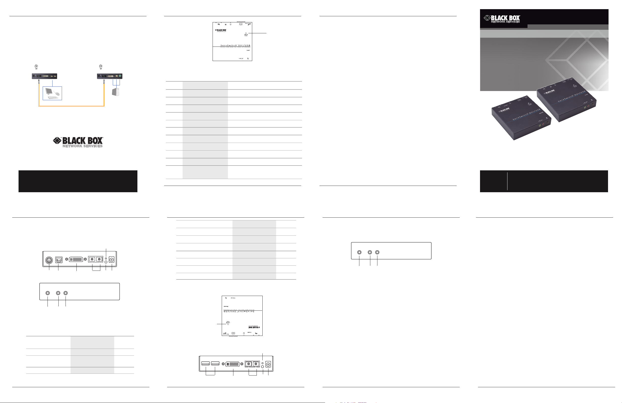
Page 1
Chapter 4: Operation/Chapter 5: Application Diagram
Chapter 2: Overview
Chapter 3: Installation
ACS 261A-S M
4. Operation
The LEDs on the Extender Units show the real-time status indicating the linking and
communication between the Console Unit and Computer Unit. Users can identify the present
status through the LED indicator on the top. See Figures 2-3 and 2-6 and Tables 2-1 and 2-2.
The quality of the output signal will depend largely upon the quality of video source, cable,
and display device used. Low-quality cables degrade the output signal causing elevated noise
levels. Use the proper cable and make sure the display device can handle the resolution and
refresh rate sele cted.
5. Application Diagram
IR receiver
© Copyrigh t 2012. Black Box Corporati on. All rights r eserve d. Black Box® and the Double Diamond
logo are registered trademarks of BB Technologies, Inc. Any third-part y trademarks appearing in
this manua l are ack nowled ged to b e the pro perty of the ir respe ctive owners .
ACS261A-SM , version 1
ACS261A-SM
Conso le
Unit
Single-mode
Conso le
fiber optic cable
Figure 5 -1. Typical installation.
ACS261A-SM
Computer
Unit
IR transceiver
Computer
FREE! Live, 24/7 Tech Support is just 30 seconds away.
724-746-5500 | blackbox.com
11
Figure 2-6. Computer unit top panel.
Table 2-2. Computer Unit components.
Number Component Description
1 Audio connector Connects to speaker
2 Audio connector Connects to microphone
3 IR control jack Plug in the external sensor here
4 Barrel connector Links to power
5 Link OK LED Flashing yellow: Link OK
6 (2) SC connectors Connect to fiber
7 DVI connector Links to computer video port
8 (1) USB Type B connec tor
9 (1) 6-pin mini D IN connector Connects to computer PS/2 keyboard and mouse
10 Reset button Resets unit
11 Link OK/Power LED
ACS261A-SM
724-746-5500 | blackbox.com
Connects to computer keyboard and mouse
Green: Power on
Blue: Link OK
3. Installation
• Power off all devices that will be connected to this system.
• Make sure that all devices you will connect are properly grounded.
• Place units away from fluorescent lights, air conditioners, and machines that are likely to
generate electrical noise.
• Determine where the Console Unit and the Computer Unit will be located.
• Use SC to SC duplex single-mode fiber optic cable (8–10 µm) for the interconnection between
Console Unit and Computer Unit.
• Make sure that the fiber cable length is long enough for the connection between the Console
Unit and the Computer Unit to prevent having to splice fiber.
• Never attempt to disassemble or reassemble the enclosure for any purpose. This may cause
personal injur y and /or proper ty damage.
Considerations for Duplex Optical Fiber Installation
1. Users may need to order appropriate cable lengths conforming to the application environment;
however, the maximum cable length should not exceed 3200 ft. (1000 meters). Otherwise, the
video resolution signal may degrade.
2. Do not exceed the cable bend radius. Fiber optic cable can break when kinked or bent too
tightly, especially during pulling.
3. Do not twist the cable. Twisting the cable can stress the fibers. Tension on the cable and
pulling ropes can cause twisting.
CAUTION: Do not look into the ends of any fiber optic cables. You might be exposed to harmful
invisible laser radiation.
4. Follow the cable manufacturer's recommendations. Fiber optic cable is often custom designed
for the installation, and the manufacturer may have specific instructions on it s inst allation.
Installing the Ex tender
Users can connect the video source and keyboard and mouse ports to the Computer Unit;
connect the keyboard, mouse, and monitor to the Console Unit; and use an SC to SC duplex
fiber optic cable for the SC-SC fiber port connection between the Console Unit and the
Computer Unit. After all device connections are completed, connect the provided power cord
into an appropriate power source and plug the opposite end into the power connector on the
Unit to p ower up.
Page 5 Page 6
ACS261A-SM
724-746-5500 | blackbox.com
DVI-D USB Fiber Extender Single-Mode with Audio
Using fiber optic cable, place a computer up to
3280 feet (1000 m) away from a console.
Customer
Support
Information
Order toll-free in the U.S.: Call 877-877-BBOX (outside U.S.
call 724-746-5500) • FREE technical support 24 hours a day, 7 days
a week: Call 724-746-5500 or fax 724-746-0746 • Mailing address:
Black Box Corporation, 1000 Park Drive, Lawrence, PA 15055-1018
Web site: www.blackbox.com • E-mail: info@blackbox.com
Page 4
724-746-5500 | blackbox.com
Figure 2-5. Computer Unit back panel.
10
4 5 6 7 8 9
Figure 2-4. Computer Unit front panel.
1 2 3
Blue: Link OK
Red: Power on
Table 2-1 (continued). Console Unit components.
10 Link OK/Power LED
9 Reset button Resets unit
8 Link OK LED Flashing yellow: Link OK
Number Component Descriiption
ACS261A-SM
Table 2-2 describes the components.
Figures 2-4 through 2-6 show the front, back, and top panels of the Computer Unit.
2.4.2 Computer Unit
Page 3
10
724-746-5500 | blackbox.com
Table 2-1. Console Unit components.
Figure 2-3. Console Unit top panel.
Figure 2-2. Console Unit back panel.
9
4 8 5 6 7
ACS261A-SM
7 (2) USB Type A connectors Keyboard/mouse
6 Video connector Connects to DVI monitor
5 (2) SC connectors Connects to fiber inter face
4 Barrel connector Links to 9 VDC power supply
3 IR control jack Plug in the external sensor here
2 Audio connector Connects to microphone
1 Audio connector Connects to speaker
Number Component Descriiption
Page 2
1 2 3
724-746-5500 | blackbox.com
Figure 2-1. Console Unit front panel.
ACS261A-SM
Page 1
724-746-5500 | blackbox.com
ACS261A-SM
• Supports P S2/ USB P C or K VM.
resolution of Full HD (1920 x 1080) or WUXGA (1920 x 1200).
3280 feet (1000 meters) away from a computer with the
• Remotely locate the keyboard, mouse and monitor up to
• KVM Extender pair connects via fiber optic s cable.
2.1 Features
Place a computer up to 3280 feet (100 0 m) from a console (keyboard/mouse /monitor).
2. Overview
describes the components.
Figures 2-1 through 2-3 show the front, back, and top panels of the Console Unit. Table 2-1
2.4.1 Console Unit
2.4 Hardware Description
• USB Type A-B cable
• DVI cable and audio cable
• USB keyboard /mouse for K VM control
2.3 System Requirements
• This user’s manual
• (2) sets of foot pads
• SC-SC Fiber Optic Cable (for test)
• (2) power supplies with power cord
• PS/2 Y Cable
• Extender Computer Unit
• Extender Console Unit
info@ blackbox.com.
If anything is missing or damaged, contact Black Box Technical Support at 724-746-5500 or
Your package should contain the following items.
2.2 What’s Included
• Supports human interface devices (HIDs) (keyboards, mice, etc.)
• Supports surge protection
• Supports EDID for high-definition display.
Weight — 1.34 lb. (0.61 kg)
1.1”H x 5.2”W x 5.1”D (2.7 x 13.1 x 13 cm)
Size — Each unit (Console and Computer units):
NOTE: The unit can support 9 –12 VDC.
Power Supply — 9 VDC, 1.5 amp
(1) fiber optic signal LED
Indicators — (1) dual-color Power/Link Status LED,
connection.
NOTE: When USB and PS/2 are connected simultaneously, USB has a higher priorit y than PS/2
Audio Jack: (1) for microphone, (1) for speaker
Remote Control Jack: (1) for IR transmitter;
(Y-cable included),
Keyboard and Mouse: (1) USB plus (1) PS/ 2
Computer unit: Monitor: (1) DVI female,
Audio Jack: (1) for microphone, (1) for speaker;
Remote Control Jack: (1) for IR receiver,
Monitor: (1) DVI female,
Console unit: Keyboard /M ouse: (2) USB Type A,
Connectors —
Video Resolution (Max.) — WUXGA (1920 x 1200)/Full HD (1920 x 1080)
Unit Connection — Fiber optics
Extension Distance — 3280 ft. (1000 m)
1. Specifications
might be exposed to invisible laser radiation. The laser beam can cause injury to the eye.
CAUTION: Do not s tare into beam or view directly into the ends of any fiber optic cables. You
Chapter 2: Overview
Chapter 2: Overview
Chapter 2: Overview
Chapter 1: Specifications; Chapter 2: Overview
 Loading...