

Page 1
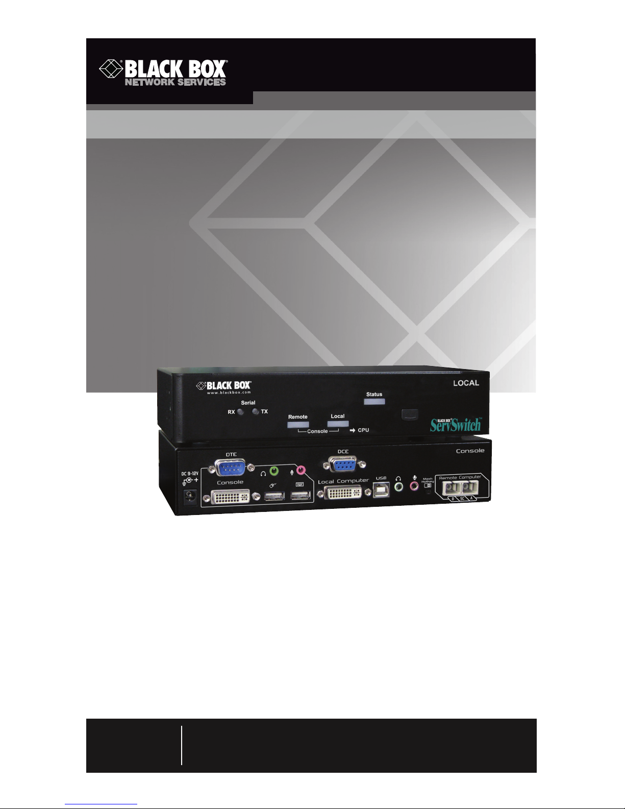
Pure digital extension over fiber optic cable
with zero compression technology. Supports EDID,
stereo audio, and serial port control.
ServSwitch™ Brand DVI-D USB KVM-over-Fiber Extender
Order toll-free in the U.S.: Call 877-877-BBOX (outside U.S. call 724-746-5500) •
FREE technical support 24 hours a day, 7 days a week: Call 724-746-5500 or fax
724-746-0746 • Mailing address: Black Box Corporation, 1000 Park Drive, Lawrence,
PA 15055-1018 • Web site: www.blackbox.com • E-mail: info@blackbox.com
Customer
Support
Information
March 2010
ACS260A-U-MM
Page 2

Page 2
724-746-5500 | blackbox.com
ServSwitch Brand DVI-D USB KVM-over-Fiber Extender
FEDERAL COMMUNICATIONS COMMISSION AND
INDUSTRY CANADA RADIO FREQUENCY INTERFERENCE STATEMENTS
This equipment generates, uses, and can radiate radio-frequency energy,
and if not installed and used properly, that is, in strict accordance with the
manufacturer’s instructions, may cause inter ference to radio communication.
It has been tested and found to comply with the limits for a Class A computing
device in accordance with the specifications in Subpart J of Part 15 of FCC rules,
which are designed to provide reasonable protection against such interference
when the equipment is operated in a commercial environment. Operation of
this equipment in a residential area is likely to cause interference, in which case
the user at his own expense will be required to take whatever measures may be
necessary to correct the interference.
Changes or modifications not expressly approved by the party responsible
for compliance could void the user’s authority to operate the equipment.
This digital apparatus does not exceed the Class A limits for radio noise
emis sion from digital apparatus set out in the Radio Interference Regulation
of Industry Canada.
Le présent appareil numérique n’émet pas de bruits radioélectriques dépassant les
limites applicables aux appareils numériques de la classe A prescrites dans le
Règlement sur le brouillage radioélectrique publié par Industrie Canada.
Page 3

Page 3
724-746-5500 | blackbox.com
NOM Statement
Normas Oficiales Mexicanas (NOM)
Electrical Safety Statement
INSTRUCCIONES DE SEGURIDAD
1. Todas las instrucciones de seguridad y operación deberán ser leídas antes de que
el aparato eléctrico sea operado.
2. Las instrucciones de seguridad y operación deberán ser guardadas para
referencia futura.
3. Todas las advertencias en el aparato eléctrico y en sus instrucciones de operación
deben ser respetadas.
4. Todas las instrucciones de operación y uso deben ser seguidas.
5. El aparato eléctrico no deberá ser usado cerca del agua—por ejemplo, cerca de la
tina de baño, lavabo, sótano mojado o cerca de una alberca, etc.
6. El aparato eléctrico debe ser usado únicamente con carritos o pedestales que sean
recomendados por el fabricante.
7. El aparato eléctrico debe ser montado a la pared o al techo sólo como sea
recomendado por el fabricante.
8. Servicio—El usuario no debe intentar dar servicio al equipo eléctrico más allá
lo descrito en las instrucciones de operación. Todo otro servicio deberá ser
referido a personal de servicio calificado.
9. El aparato eléctrico debe ser situado de tal manera que su posición no
interfiera su uso. La colocación del aparato eléctrico sobre una cama, sofá,
alfombra o superficie similar puede bloquea la ventilación, no se debe
colocar en libreros o gabinetes que impidan el flujo de aire por los orificios
de ventilación.
10. El equipo eléctrico deber ser situado fuera del alcance de fuentes de calor
como radiadores, registros de calor, estufas u otros aparatos (incluyendo
amplificadores) que producen calor.
11. El aparato eléctrico deberá ser connectado a una fuente de poder sólo del tipo
descrito en el instructivo de operación, o como se indique en el aparato.
12. Precaución debe ser tomada de tal manera que la tierra fisica y la polarización
del equipo no sea eliminada.
Page 4

Page 4
724-746-5500 | blackbox.com
ServSwitch Brand DVI-D USB KVM-over-Fiber Extender
13. Los cables de la fuente de poder deben ser guiados de tal manera que no
sean pisados ni pellizcados por objetos colocados sobre o contra ellos,
poniendo particular atención a los contactos y receptáculos donde salen del
aparato.
14. El equipo eléctrico debe ser limpiado únicamente de acuerdo a las
recomendaciones del fabricante.
15. En caso de existir, una antena externa deberá ser localizada lejos de las
lineas de energia.
16. El cable de corriente deberá ser desconectado del cuando el equipo no sea
usado por un largo periodo de tiempo.
17. Cuidado debe ser tomado de tal manera que objectos liquidos no sean
derramados sobre la cubierta u orificios de ventilación.
18. Servicio por personal calificado deberá ser provisto cuando:
A: El cable de poder o el contacto ha sido dañado; u
B: Objectos han caído o líquido ha sido derramado dentro del aparato; o
C: El aparato ha sido expuesto a la lluvia; o
D: El aparato parece no operar normalmente o muestra un cambio en su
desempeño; o
E: El aparato ha sido tirado o su cubierta ha sido dañada.
Page 5

Page 5
724-746-5500 | blackbox.com
Trademarks Used in this Manual
TRADEMARKS USED IN THIS MANUAL
Black Box and the Double Diamond logo are registered trademarks, and
ServSwitch is a trademark, of BB Technologies, Inc.
Any other trademarks mentioned in this manual are acknowledged to be
the property of the trademark owners.
Page 6

Page 6
724-746-5500 | blackbox.com
ServSwitch Brand DVI-D USB KVM-over-Fiber Extender
Contents
Chapter Page
1. Specifications...................................................................................... 7
2. Overview ......................................................................................... 8
2.1 Introduction ................................................................................ 8
2.2 Features ...................................................................................... 8
2.3 What’s Included .......................................................................... 9
2.4 What You Need to Supply ........................................................ 10
2.5 Hardware Description ............................................................... 10
2.5.1 Console Unit ................................................................... 10
2.5.2 Computer Unit ............................................................... 12
2.6 Typical Application .................................................................... 14
3. Installation ....................................................................................... 15
3.1 Using Fiber Optic Cable ............................................................. 15
3.2 Before Installation ..................................................................... 16
3.3 Installation Steps ....................................................................... 16
3.3.1 Console Unit ................................................................... 16
3.3.2 Computer Unit ............................................................... 16
4. Operation ....................................................................................... 17
4.1 LED Indicators ........................................................................... 17
4.2 Selecting Computers Using Push Buttons ................................. 18
4.2.1 Push Button on Console Unit ......................................... 18
4.2.2 Push Button on Computer Unit ...................................... 18
4.3 Selecting Computers Using Keyboard Hotkey Commands ........ 19
4.3.1 Mask Hotkey Switch ....................................................... 20
4.3.2 Hotkey Commands ......................................................... 22
4.3.3 Push Button for Alternate Hotkey Control
(Computer Unit Only) ..................................................... 27
5. Cascade Configuration ..................................................................... 28
6. Serial Configuration .......................................................................... 30
Appendix. Cable Requirements/Fiber Optic Cables/Blu-ray ..................... 31
A.1 Cable Requirements ......................................................................... 31
A.2 Fiber Optic Cables ............................................................................ 31
A.3 Blu-ray Ready ................................................................................... 31
Page 7

Page 7
724-746-5500 | blackbox.com
Chapter 1: Specifications
1. Specifications
Distance: 1080p: 3200 ft. (1000 m);
1080i: 6400 ft. (2000 m)
HDCP Support: Yes
Hotkey: Yes
Video Resolution (Maximum): Full HD: 1920 x 1080;
WUXGA: 1920 x 1200
User Controls: Each unit: (1) Push Button: Control Status Switch
Connectors:
Console Unit:
Console Interface: Serial port: (1) DB9 M DTE;
Keyboard and mouse: (2) USB Type A F,
Monitor: (1) DVI-I F;
Audio jack: (1) speaker and (1) microphone;
Computer Interface:
Serial port: (1) DB9 F DCE;
Keyboard and mouse: (1) USB Type B F,
Monitor: (1) DVI-I F,
Audio: (1) speaker and (1) microphone;
Interconnect: (1) duplex SC;
Computer Unit:
Console Interface: (1) DB9 M DTE;
Keyboard and mouse: (1) USB Type A F;
Monitor: (1) DVI-I F;
Audio jack: (1) speaker and (1) microphone;
Interconnect: (1) duplex SC;
Computer Interface: Serial port: (1) DB9 F DCE;
Keyboard and mouse: (1) USB Type B F;
Monitor: (1) DVI-I F;
Audio jack: (1) speaker and (1) microphone
Indicators: (5) LEDs: (1) Status, (1) Local, (1) Remote, (2) Serial
Power: Each unit: 9-12 VDC, 1.5 A
Size: Each unit: 1.7"H x 8.6"W x 5.2"D (4.4 x 21.8 x 13 cm)
Page 8

Page 8
724-746-5500 | blackbox.com
ServSwitch Brand DVI-D USB KVM-over-Fiber Extender
2. Overview
2.1 Introduction
The DVI-D USB KVM over Fiber Optic Extender consists of a console unit and a
computer unit. It enables you to remotely access and control a computer or KVM
switch up to 6400 feet (2000 m) away from using only fiber optic cable.
The extender optimizes the digital display up to a maximum resolution of Full HD
(1920 x 1080)/WUXGA (1920 x 1200)/UXGA (1600 x 1200). For cascaded applications, the dedicated Mask Hotkey switch masks the master KVM extender level,
enabling users to directly configure the slave level KVM switch as if the user were
sitting in front the slave KVM switch. This saves time, prevents errors, and makes
the hotkey configuration more predictable.
This KVM extender includes dual-user access, the ability to control multiple
computers through cascading with a KVM switch, push button for switching
control, front-panel LED for status indication, hotkey control and mask hotkey
switch for easy computer access, serial interface for instant data transfer, HDCP
compliance, Blu-ray display support, and audio jack (speaker + microphone)
for broadcasting. Besides, it is fully compatible with most popular monitor screen
resolutions such as XGA, SXGA, UXGA, WSXGA all the way to Full HD, WUXGA
system.
Ideal for transmission security, the extender eliminates electromagnetic radiation
emission. Use it for a variety of KVM extension applications, including in medical,
military, industrial, and high electromagnetic interference (EMI)/radio frequency
interference (RFI) environments where real-time, high-resolution audio/video
transmission is essential. The extender also enables you to secure the computers
and valuable data or manage them both in remote and local sites. No software
or DIP switches are required, just plug and play.
2.2 Features
• Connect the KVM extender pair via fiber optic cable
• Remotely locate the keyboard, mouse and monitor up to 6400 feet
(2000 meters) away from a computer (or a KVM switch) with a maximum
resolution of Full HD (1920 x 1080)/WUXGA (1920 x 1200)/UXGA (1600 x
1200)
• Supports USB console
• Hotkey functions for easy computer access
Page 9

Page 9
724-746-5500 | blackbox.com
Chapter 2: Overview
• Mask Hotkey Switch on the rear panel masks the cascaded KVM extender itself
and directly configures KVM switch controls to the computer that’s attached to
the KVM switch.
• Can provide dual-user access to share multiple computers when KVM switch
is cascaded
• Fiber optic connectors provide high-speed and long-distance transmission
• Supports serial interface for instant data transfer
• Fully compatible with DVI and/or HDMI standard by DDWG
• HDCP-compliant and Blu-ray ready
• Completely free from electromagnetic interference (EMI)
• Ideal for professional audio/video applications
• Optional fiber-only system without DDC function (pseudo DDC signal can be
transmitted for EDID information.)
• Uses multimode optical fiber
• Transmits video digitally for zero signal loss
• Compatible with most opular screen resolutions for XGA, SXGA, UXGA,
WSXGA all the way to Full HD, WUXGA system
2.3 What’s Included
Your package should contain the following items. If anything is missing or
damaged, contact Black Box Technical Support at 724-746-5500.
• (1) KVM Extender console unit
• (1) KVM Extender computer unit
• (2) power adapters
• (2) power cords
• (2) sets [(8) pieces] foot pads
• (2) sets of DVI 2-to-2 USB cable with audio cable
• (2) sets of rackmount brackets with screws
• (1) 96-foot (30-m) fiber optic cable
• This user’s manual
Page 10
Page 10
724-746-5500 | blackbox.com
ServSwitch Brand DVI-D USB KVM-over-Fiber Extender
2.4 What You Need to Supply
• (1) computer with USB port(s) and DVI video output port
• (1) USB keyboard/mouse to control the console
• Microphone, speakers, HDCP-compliant monitors with DVI interface for the
HDCP video source (optional)
• DVI KVM cable(s)
• Fiber cable
• Serial cable (for serial device applications)
2.5 Hardware Description
2.5.1 Console Unit
Front Panel
Figure 2-1 shows the DVI-D USB KVM over Fiber Optic Extender Console Unit’s
front panel. Table 2-1 describes its components.
1 2 3 4 5 6
Figure 2-1. Console unit’s front panel.
Table 2-1. Console unit’s front panel components.
Number Component Description
1 Serial LED indicator RX: Data receive
2 Serial LED indicator TX: Data transmit
3 Remote LED indicator Control status
4 Local LED indicator Control status
5 Status LED indicator Green: Power on
Blue: Power on and connected to a local
unit
6 Push button Select control status
Page 11

Page 11
724-746-5500 | blackbox.com
Chapter 2: Overview
Back Panel
Figure 2-2 shows the extender console unit’s back panel. Table 2-2 describes its
components.
DTE DCE
REMOTE
Console Local Computer
Remote Computer
DC 9-12V
SCB
USB
A
17 8 9 9 13 14 15 15 11 16
7 10 10 12
Figure 2-2. Console unit’s back panel.
Table 2-2. Console unit’s back panel components.
Number Component Description
7 DTE interface Connects to a serial device
8 DVI connector Connects to the monitor
9 USB Type A connectors Connects to the console’s mouse or
keyboard and mouse combo
10 Audio jacks Connects to speakers and microphone
11 Mask hotkey OFF: Standard mode
ON: Disables the KVM extender
hotkey function
12 DCE interface Connects to a serial port
13 DVI connector Connects to local PC’s video output
14 USB Type B connector Connects to local PC’s USB keyboard/
mouse port
15 Audio jacks Connects to local PC’s audio ports
16 SC duplex fiber interface Connects to multimode fiber
17 Power supply Supplies power to the unit
Page 12

Page 12
724-746-5500 | blackbox.com
ServSwitch Brand DVI-D USB KVM-over-Fiber Extender
2.5.2 Computer Unit
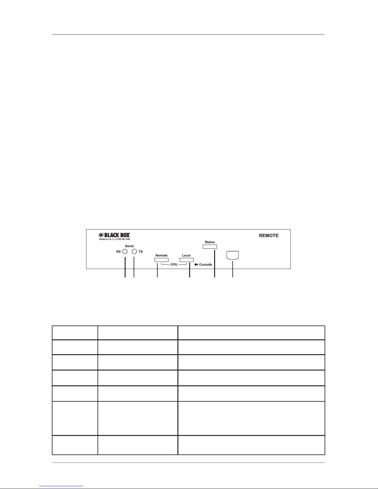
Front Panel
Figure 2-3 shows the DVI-D USB KVM over Fiber Optic Extender Computer Unit’s
front panel. Table 2-3 describes its components.
1 2 3 4 5 6
Figure 2-3. Computer unit’s front panel.
Table 2-3. Computer unit’s front panel components.
Number Component Description
1 Serial LED indicator RX: Data receive
2 Serial LED indicator TX: Data transmit
3 Remote LED indicator Control status
4 Local LED indicator Control status
5 Status LED indicator Green: Power on
Blue: Power on and connected to a
remote unit
6 Push button Select control status
Page 13

Page 13
724-746-5500 | blackbox.com
Chapter 2: Overview
Back Panel
Figure 2-4 shows the extender computer unit’s back panel. Table 2-4 describes its
components.
17 8 9 9 13 14 15 15 11 16
7 10 10 12
DTE DCE
LOCAL
Local Console Computer
Remote Console
DC 9-12V
SCB
USB
A
Figure 2-4. Computer unit’s back panel.
Table 2-4. Computer unit’s back panel components.
Number Component Description
7 DTE interface Connects to a serial device
8 DVI connector Connects to the monitor
9 USB Type A connectors Connects to the computer’s mouse or
keyboard and mouse combo
10 Audio jacks Connects to speakers and microphone
11 Mask hotkey OFF: Standard mode
ON: Disables the KVM extender
hotkey function
12 DCE interface Connects to a serial port
13 DVI connector Connects to remote PC’s video output
14 USB-B connector Connects to remote PC’s USB
keyboard/mouse port
15 Audio jack Connects to remote PC’s audio ports
16 SC duplex fiber interface Connects to multimode fiber
17 Power supply Supplies power to the unit
Page 14

Page 14
724-746-5500 | blackbox.com
ServSwitch Brand DVI-D USB KVM-over-Fiber Extender
2.6 Typical Application
Figure 2-5 shows a typical application of the extender.
Console Unit
Computer Unit
Figure 2-5. Typical application.
Page 15

Page 15
724-746-5500 | blackbox.com
Chapter 3: Installation
3. Installation
3.1 Using Fiber Optic Cable
1. Use multimode fiber optic cable (50/125 and 62.5/125) terminated with SC
connectors to link the computer unit and the console unit. Table 3-1 lists
applicable specifications.
Table 3-1. Fiber optic cable specifications.
Cable Diameter 50/125 µm 62.5/125 µm
Video Signal 1080i 1080p 1080i 1080p
Maximum Cable Length 6400 ft./ 3200 ft./ 2240 ft./ 1120 ft./
2000 m 1000 m 700 m 350 m
2. Use different cable lengths according to the application environment; however,
the maximum cable length should be less than 6400 feet (2000 meters).
Otherwise, the video resolution signal might degrade.
3. Check the cable length to make sure the cable being pulled is long enough for
the run to prevent having to splice fiber. Try to complete the installation in one
pull. Before installation, assess the route carefully to determine the methods of
installation and obstacles likely to be encountered.
4. Do not exceed the cable bend radius. Fiber optic cable can be broken when
kinked or bent too tightly, especially during pulling.
5. Do not twist the cable. Twisting the cable can stress the fibers. Tension on the
cable and pulling ropes can cause twisting.
6. Don’t look into the ends of any fiber optic cables. Invisible laser radiation might
damage your eyes.
7. Connector and splice loss is caused by a number of factors. Loss will be minimized when the number of connections and splices is reduced, the two fiber
cores are identical and perfectly aligned, the connectors or splices are properly
finished, and no dirt is present.
8. Although most fiber optic cables are not conductive, any metallic hardware
used in fiber optic cabling systems (such as wall-mounted termination boxes,
racks, and patch panels) must be grounded.
Page 16

Page 16
724-746-5500 | blackbox.com
ServSwitch Brand DVI-D USB KVM-over-Fiber Extender
9. Conductive cables require proper grounding and bonding for applicable
conductors.
10. Carefully inspect all fiber optic components for damage and test it for continu-
ity or loss if you suspect damage.
11. Move small, lightweight spools of fiber optic cable by hand. Move larger reels
with appropriate lifting equipment or use two or more installers skilled in the
moving operation.
12. Follow the cable manufacturer's recommendations. Fiber optic cable is often
custom designed for the installation and the manufacturer may have specific
instructions on its installation.
3.2 Before Installation
NOTE: See Figure 2-5 for a sample installation.
1. Make sure that all the devices you will connect are properly grounded.
2. Before installation, make sure that all the devices you will connect to this
system are powered off.
3. The KVM Extender is HDCP compliant. Use an HDCP-compliant display when
connecting to the HDCP video source.
3.3 Installation Steps
3.3.1 Console Unit
1. Connect the console DVI-I connector to the monitor.
2. Connect the console USB Type A connectors to the keyboard/mouse.
3. Link the speakers/microphone connectors to the console‘s audio ports.
4. Connect the console unit‘s computer connectors to the computer’s DVI-I
monitor, USB Type B keyboard/mouse, and speakers/microphone.
3.3.2 Computer Unit
1. Connect the computer unit’s console DVI-I connector to the monitor.
2. Connect the computer unit‘s console USB Type A connectors to the keyboard/
mouse.
3. Link the speakers/microphone connectors to the computer unit’s console audio
ports.
4. Connect the computer unit‘s computer connectors to the computer’s DVI-I
monitor, USB Type B keyboard/mouse, and speakers/microphone.
5. Use a multimode fiber optic cable for the SC–SC fiber port connection between
the console and the computer unit. After all device connections are completed,
connect the provided power cord into an appropriate power source and plug
the opposite end into the power connector on the unit to power up.
Page 17

Page 17
724-746-5500 | blackbox.com
Chapter 4: Operation
4. Operation
4.1 LED Indicators
The LEDs on the KVM extender indicate the latest link, communication, and
control status between the Computer Unit and Console Unit.
1. Press the push button on Console Unit to select “Local ON” or “Remote ON.”
2. Press the push button on Computer Unit to select “Local ON,” “Remote ON,”
or “Auto Mode.”
Table 4-1. LEDs on the Console Unit.
LED Status Control Description
Remote Off Console unit controls its local PC.
Local On*
Remote On Console unit is remotely taking control
Local Off of the computer unit. In this mode, there
are two possible statuses: 3 LEDs flashing
or 3 LEDs not flashing.
3 LEDs (Num, Flashing The computer unit is now taking control
Caps, and of the system.
Scroll lock)
3 LEDs (Num, Not flashing The system is waiting for the console
Caps, and unit or computer unit to take control.
Scroll lock)
*By default, the LED status is set to Local On when the console unit powers on.
Table 4-2. LEDs on the Computer Unit.
LED Status Control Description
Remote Off Computer unit controls its local PC or KVM
Local On switches. In this mode, the console unit
can not take control of the computer unit
remotely.
Remote On Console unit remotely takes control
Local Off of the computer unit.
Remote/ Flash The system is waiting for the console unit
Local alternately or computer unit to take control. The
(Auto mode)* control power is on a first-come, first served basis.
*By default, the LED status is set to Auto when the computer unit powers on.
Page 18

Page 18
724-746-5500 | blackbox.com
ServSwitch Brand DVI-D USB KVM-over-Fiber Extender
4.2 Selecting Computers Using Push Buttons
The Computer Unit and the Console Unit’s front panels each have a push button.
Push these buttons in sequence to switch between operation modes.
4.2.1 Push Button on the Console Unit
The button on the front panel of the Console Unit can be used to switch modes
by following the sequence below:
Local On—>Remote On—>Local On—>Remote On
Local On: The Local LED lights to indicate that the console unit is taking control of
its local computer.
Remote On: The Remote LED lights to indicate that the console unit is remotely
taking control of the Computer Unit.
4.2.2 Push Button on the Computer Unit
Through pressing the button, three modes will be generated in the sequence as
shown below:
Auto—>Local On—>Remote On—>Auto—>Local On—>Remote On
Auto:
1. The Remote and Local LEDs flash alternately.
2. The system is now waiting for the Console or the Computer Unit to take
control. The control priority is on a first-come, first-served basis.
For example, once the keyboard or mouse of the Computer Unit is active, the
Local LED will light and the Remote LED will go off. This status indicates that the
Computer Unit is now taking control on its local computer or KVM switch, and
vice versa for the Console Unit. In Auto mode, you can preset the duration of
latch time for taking control to 5, 15, 30, or 60 seconds via hotkeys, which
enables the Computer or Console Unit to resume control again via any keystroke
or mouse activity if the latch time is due and the status returns to the “Auto”
mode.
In “Auto” mode whenever the Computer Unit or Console Unit detects any activity
from the keyboard, mouse buttons, or mouse’s scroll wheel, the Computer Unit or
Console Unit immediately takes control of the system.
Local: The Local LED lights when the computer unit is taking control on its local
computer or KVM switch. In this case, the user in Console Unit can identify this
status from the flashing of 3 LEDs (Num, Caps, and Scroll Lock) on the keyboard.
Remote: The Remote LED lights when the system is remotely controlled by the
Console Unit.
Page 19

Page 19
724-746-5500 | blackbox.com
Chapter 4: Operation
4.3 Selecting Computers Using Keyboard Hotkey Commands
A hotkey command is a short key sequence that selects a computer, activates a
computer scan, etc. The KVM extender interprets keystrokes for hotkeys all the
time no matter what the connection pattern is.
Standard Mode is defined as the state of the KVM extender without any
connection to any KVM switch.
Compatibility Mode is defined as the state of the KVM extender with
connection(s) to KVM switch(es).
In Command for Switch Mode, users can switch modes between Standard and
Compatibility by pressing the hotkey command [left-Ctrl + left-Ctrl + Alt+E]. The
unit then generates one beep to confirm Standard Mode or two beeps to confirm
Compatibility Mode.
Leading Code
In Standard Mode, a hotkey command starts with the leading code
[left-Ctrl + left-Ctrl] followed by one or two more keystrokes.
In Compatibility Mode, a hotkey command starts with the leading code
[left-Ctrl + left-Ctrl + E] followed by one or two more keystrokes.
The built-in buzzer generates either a high-pitched beep for a correct hotkey
command or one short and one long beep for a bad command. The bad key
command won’t be sent to the selected computer.
Mask Hotkey Switch
The hotkey commands differ depending on the model. Errors or unpredictable
results might occur between the Extender Unit and mixed KVM switch types that
connect to each other. A shortcut for cascade hotkey configuration, the Mask
Hotkey Switch, allows users to bypass the Extender Unit and directly apply the
cascaded KVM switch’s built-in hotkey commands on the Extender Unit. This feature will be described in more detail in Section 4.3.1.
Alternate Hotkey Approach
You can press the front-panel push button and one keystroke as an alternate
hotkey for a specific hotkey feature set to the user’s preference. The KVM
extender can not conduct any hotkey controls when its hotkey function is masked
(Hotkey Mask Switch “ON”); this alternate approach is especially useful in this
state. See Section 4.3.2 for more information.
Page 20

Page 20
724-746-5500 | blackbox.com
ServSwitch Brand DVI-D USB KVM-over-Fiber Extender
Figure 4-1. Alternate hotkeys activated on keyboard.
4.3.1 Mask Hotkey Switch
Slide the Mask Hotkey Switch (shortcut for Cascade Hotkey Configuration) located
at the rear panel of both Console Unit and Computer Unit ON/OFF to switch hotkey control between the KVM switch cascaded/computer connected accordingly.
The factory default is set to “OFF.”
Table 4-3. Mask hotkey switch functions.
Mask Hotkey Switch In Cascade In Non-Cascade
Architecture Architecture
ON The Extender Unit masks The Extender Unit hotkey
itself. Users can directly function is disabled.
configure the computers
attached to the KVM
switch by applying the
KVM switch’s built-in
hotkey commands.
OFF Users can configure the Users can configure the
computer attached to the computer attached to the
KVM switch by applying extender unit by applying
the KVM extender’s KVM extender’s built-in
built-in hotkey command hotkey command prefixed
prefixed with the cascade with the non-cascade
leading code [left-Ctrl + leading code [left-Ctrl +
left-Ctrl + E]. left Ctrl].
Page 21

Page 21
724-746-5500 | blackbox.com
Chapter 4: Operation
Example of Mask Hotkey set to “ON” in cascade architecture
An IT administrator sitting in front of the Console Unit can preset the Console
Unit to remote mode for accessing the KVM Switch that is attached to the
Computer Unit, then slide “ON” the Mask Hotkey Switch on the Console Unit.
After that, the administrator can directly apply the KVM Switch’s built-in hotkey
commands on the Console Unit to configure the computer that’s attached to the
KVM switch. See Section 4.3.2 for more information.
KVM Switch
Computer Unit
Console Unit
LED: Remote On
Mask Hotkey: On
Figure 4-2. Console unit preset to access the KVM switch
that’s attached to the Computer Unit.
Computer Unit
Console Unit
KVM Switch
Mask Hotkey On:
directly control
the computer
Figure 4-3. Apply KVM switch’s hotkey commands on the Console Unit
to the attached Computer Unit.
Page 22

Page 22
724-746-5500 | blackbox.com
ServSwitch Brand DVI-D USB KVM-over-Fiber Extender
4.3.2 Hotkey Commands
• Before inputting any hotkey commands, enable either of two modes:
Standard Mode: Input the hotkey command [left Ctrl + left Ctrl + Alt + E]. The
unit will beep once to confirm.
Compatibility Mode: Input the hotkey command [left Ctrl + left Ctrl + Alt + E].
The unit will beep twice to confirm.
NOTE: Users can switch the modes alternately by repeating this hotkey command.
• Only the Ctrl key located on the lower-left corner of the keyboard is valid for
hotkey commands.
• The hotkey command will automatically time-out if the keyboard detects no
activity within three seconds after you input the leading code.
• When the mask hotkey switch is set to “ON,” the extender unit masks itself.
In this state, users can sit in front of the extender and directly apply the KVM
switch built-in hotkey commands to configure the computers attached to the
KVM switch as if the users were virtually sitting in front of the KVM switch.
Table 4-4. Console unit hotkey commands and their functions.
Mask Hotkey: OFF Mask Hotkey: ON Function Description
Hotkey Alternate Hotkey Alternate
Hotkey Hotkey
[Ctrl]+[Ctrl]+Alt+E N/A N/A N/A Select cascading status.
Two beeps enable
Compatibility Mode, and
the user at the console unit
accesses the KVM switch
connected to the computer
unit.
One beep disables
Compatibility Mode.
[Leading Code]+Esc N/A N/A N/A Escape from Hotkey Mode.
[Leading Code]+T N/A N/A N/A Mode selection in
sequence. Switch console
control between the local
computer and the remote
computer.
Page 23

Page 23
724-746-5500 | blackbox.com
Chapter 4: Operation
Table 4-4 (Continued). Console unit hotkey commands and their functions.
Mask Hotkey: OFF Mask Hotkey: ON Function Description
Hotkey Alternate Hotkey Alternate
Hotkey Hotkey
[Leading Code]+F2 N/A N/A N/A Mode selection in
sequence. Switch the
console control between
local computer and remote
computer.
[Leading Code]+1 N/A N/A N/A Select local mode. Enable
the user at the console unit
to access the computer on
the console unit.
[Leading Code]+2 N/A N/A N/A Select remote mode.
Enable the user at the
console unit to exclusively
access the computer unit
(valid only if the computer
unit is in remote or auto
mode). Disable the computer unit user from
accessing the computer
unit during this mode.
Follow the KVM switch user’s manual Select KVM switch’s CPU
(applies only in compatibility mode) port.
Figure 4-4. Don’t use the numeric pad or the right Alt and Ctrl buttons.
Page 24

Page 24
724-746-5500 | blackbox.com
ServSwitch Brand DVI-D USB KVM-over-Fiber Extender
Table 4-5. Computer unit hotkey commands and their functions.
Mask Hotkey: OFF Mask Hotkey: ON Function Description
Hotkey Alternate Hotkey Alternate
Hotkey Hotkey
[Ctrl]+[Ctrl]+Alt+E N/A N/A N/A Select cascading status.
Two beeps: Enable compatibilty mode so users can
access the KVM switch
that connects to the computer unit.
One beep: Disable compat-
ibility mode.
[Leading Code]+Esc N/A N/A N/A Escape from hotkey mode
[Leading Code]+T N/A N/A N/A Select modes in sequence.
Toggle to select Auto,
Local On, or Remote On
mode.
[Leading Code]+1 N/A N/A N/A Select local mode. Enables
exclusive access for the
user at the computer unit
to the PC/KVM switch that
connects to the computer
unit. Disables the user at
the console unit from
accessing the connected
PC/KVM switch.
[Leading Code]+2 N/A N/A N/A Select remote mode.
Enables exclusive access for
the user at the console unit
to the PC/KVM switch that
connects to the computer
unit. Disables the user at
the computer unit from
accessing the connected
PC/KVM switch.
Page 25

Page 25
724-746-5500 | blackbox.com
Chapter 4: Operation
Table 4-5 (Continued). Computer unit hotkey commands and their functions.
Mask Hotkey: OFF Mask Hotkey: ON Function Description
Hotkey Alternate Hotkey Alternate
Hotkey Hotkey
[Leading Code]+3 N/A N/A N/A Select Auto mode.
[Leading Code]+F3 [BTN] N/A [BTN] Select Latch time. The
+F3 +F3 extender beeps 1 to 4
times to indicate the latch
time: 5, 15, 30, or 60
seconds.
[Leading Code]+V [BTN]+V N/A [BTN]+V DVI display mode setting
+D +D +D (factory default): Set the
display on both Console
and Computer Units to the
DVI mode that is incapable
of carrying any audio
signals.
[Leading Code]+V [BTN]+V N/A [BTN]+V HDMI display mode
+M +M +M setting: Set the display on
both Computer and
Console Units to HDMI
mode that is capable of
carrying high-definition
digital audio and video
signals.
Follow the KVM switch user’s manual Select KVM switch’s CPU
(applies only in Compatibility Mode) port.
NOTE: Standard Mode is defined as the state of the KVM extender without
additional connection to any KVM switch(es).
NOTE: [Leading Code] denotes the following:
In Standard Mode, the hotkey sequence [Ctrl]+[Ctrl].
In Compatibility Mode, the hotkey sequence [Ctrl]+[Ctrl]+E
Page 26

Page 26
724-746-5500 | blackbox.com
ServSwitch Brand DVI-D USB KVM-over-Fiber Extender
NOTE: [BTN] denotes Press and Hold the front-panel push button for two
seconds.
NOTE: After you Press and Hold the push button, the hotkey state will
automatically time out if:
1. The keyboard detects no activity within six seconds afer you press and
hold the push button for two seconds.
2. You press the [Esc] button once to exit the hotkey state.
3. You press the push button once to escape from the hotkey state and
switch to the Auto, Local, or Remote Mode.
NOTE: An alternate for the hotkey command on the Computer Unit to select latch
time is described below:
Step 1: Press and hold the Computer Unit’s front-panel push button for two
seconds.
Step 2: Press the F3 key once and listen for one, two, three, or four beeps to con-
firm the latch time setting: 5, 15, 30, or 60 seconds. Repeat Steps 1 and 2
to select the desired latch time.
Figure 4-5. Keyboard keys that don’t function as hotkeys.
4.3.3 Push Button for Alternate Hotkey Control (Computer Unit Only)
No matter whether the mask hotkey switch is set to ON or OFF, you can press and
hold the push button on the front panel for two seconds instead of entering the
leading code [Ctrl] +[Ctrl] or [Ctrl] + [Ctrl] + E for some specific hotkey control on
the Computer Unit as described below and on the next page.
• Latch time selection: Select the duration of the latch time: 5, 15, 30, or 60
seconds.
Press and Hold push button for 2 seconds + F3
Page 27

Page 27
724-746-5500 | blackbox.com
Chapter 4: Operation
• DVI mode for monitor display: Set the display(s) on both the Console and
Computer Units to DVI mode that is incapable of carrying any audio signals.
Press and hold the push button for two seconds + V + D
Console Unit
DVI Monitor
Computer Unit
DVI Monitor
Fiber Optic Cable
Figure 4-6. DVI mode for monitor display configuration.
• HDMI mode for monitor display: Set the display(s) on both Console and
Computer Units to HDMI mode that is capable of carrying high-definition digital
audio and video signals.
Press and hold the push button for two seconds + V + M
Console Unit
HDMI Monitor
Computer Unit
HDMI Monitor
Fiber Optic Cable
Figure 4-7. HDMI mode for monitor display configuration.
Refer to Section 4.3.2 for further configurations.
NOTE: By factory default, the display mode on Console and Computer Units is set
to DVI mode.
Page 28

Page 28
724-746-5500 | blackbox.com
ServSwitch Brand DVI-D USB KVM-over-Fiber Extender
5. Cascade Configuration
You can connect one KVM extender per console port of the KVM switch in a cascade configuration. To prevent any conflict between hotkey commands among
the connected units, press the E key after you press Ctrl + Ctrl to access the
extender directly. Or, use a shortcut through Hotkey Mask to significantly simplify
the cascade hotkey configuration. To manage your system, refer to the NOTES
section on the next page.
Console Unit
Computer
Unit
KVM Switch
Fiber Optic Cable
Figure 5-1. Computer Unit and Console Unit cascaded from a KVM switch.
KVM Switch
Console Unit
Computer Unit
Fiber Optic Cable
Figure 5-2. Console Unit and Computer Unit cascaded from a KVM switch.
Page 29

Page 29
724-746-5500 | blackbox.com
Chapter 5: Cascade Configuration
NOTES: Cascade Connection
1. An external power source is required to supply enough power to the
KVM extender’s Computer Unit when connecting to the KVM switch.
To purchase an optional power adapter, call Black Box Technical
Support at 724-746-5500.
2. To prevent sending wrong keystrokes for Hotkey control to the KVM
extender’s Console Unit, set up the latch time and push button control
parameters before connecting to the KVM switch.
Page 30

Page 30
724-746-5500 | blackbox.com
ServSwitch Brand DVI-D USB KVM-over-Fiber Extender
6. Serial Configuration
The KVM Extender has serial ports on both the Console and Computer units.
You can connect these serial ports to serial terminal and serial devices for device
configurations such as POS, bar-code scanners, card readers, and touch screens.
The extender units transmit data without baud rate limits or configuration.
The serial terminal baud rate setting must match the connected serial device’s
serial baud rate, shown in Figure 6-1.
Serial
Device A
PC A (DTE)
PC B (DTE)
Serial
Device B
Fiber Optic Cable
Figure 6-1. Serial configuration.
NOTE: Serial Device A—> PC A (serial terminal). Device A and PC A should have
the same baud rate setting.
Page 31

Page 31
724-746-5500 | blackbox.com
Appendix : Cable Requirements /Fiber Optic/Blu-ray
Appendix. Cable Requirements/Fiber Optic Cable/Blu-ray
A.1 Cable Requirements
A fiber optic cable terminated with multimode SC connectors is normally used to
connect the Computer Unit to the Console Unit. Your package includes a fiber
optic cable. However, you might need to order different cable lengths depending
on the application environment. (Call Tech Support at 724-746-5500 for details.)
The maximum cable length should be less than 6400 feet (2000 meters); otherwise, the video resolution signal might degrade.
A.2 Fiber Optics Cable
The KVM extender requires fiber optic cable that’s up to 6400 feet (2000 m)
long. Choose our Multimode Duplex SC Terminated Fiber Cable (EFN6025 for
50-micron; EFN4021 for 62.5-micron).
A.3 Blu-ray Ready
The KVM extender supports high-definition video such as DVD or Blu-ray and
multichannel audio. The high bandwidth allows for the transmission of large
amounts of information at a very high rate of speed.
Blu-ray uses a blue-violet laser to read and write data, while current optical disc
technologies such as DVD, DVD±R, DVD±RW, and DVD-RAM rely on a red laser
to read and write data. Blu-ray uses a blue-violet laser (405 nm) that has a shorter
wavelength than a red laser (650 nm), which makes it possible to focus the laser
spot with even greater precision. Data can be packed more tightly and stored in
less space, so you can fit more data on the disc even though it’s the same size as
a CD/ DVD.
Page 32

Black Box Tech Support: FREE! Live. 24/7.
Tech support the
way it should be.
Great tech support is just 20 seconds away at
724-746-5500 or blackbox.com.
724-746-5500 | blackbox.com
About Black Box
Black Box Network Services is your source for more than 118,000 networking
and infrastructure products. You’ll find everything from cabinets and racks and
power and surge protection products to media converters and Ethernet switches
all supported by free, live 24/7 Tech support available in 20 seconds or less.
©
Copyright 2010. All rights reserved.
 Loading...