

Page 1

Safety information
• For use in dry, oil free indoor environments only.
• Not suitable for use in hazardous or explosive environments or next to highly flammable
materials.
• Warning – the optional power adapter contains live parts.
• No user serviceable parts are contained within the module or the power adapter - do not
dismantle.
• Do not use the power adapter if the power adapter case becomes damaged, cracked or
broken or if you suspect that it is not operating properly.
• Replace the power adapter with a manufacturer approved type only.
• If you use a power extension cable with the optional power adapter, make sure the total
ampere rating of the devices plugged into the extension cable do not exceed the cable’s
ampere rating. Also, make sure that the total ampere rating of all the devices plugged into
the wall outlet does not exceed the wall outlet’s ampere rating.
DDC Ghost module
What you may additionally need
What’s in the box
D
D
C
G
h
o
st
V
G
A
S
T
AT
U
S
C
L
O
N
E
COMPUTER
MONIT
OR
Mains to 5VDC power adapter
(if power cannot be obtained from the controlling computer via the video cable)
Video cable (15 pin D-type male to 15 pin D-type male)
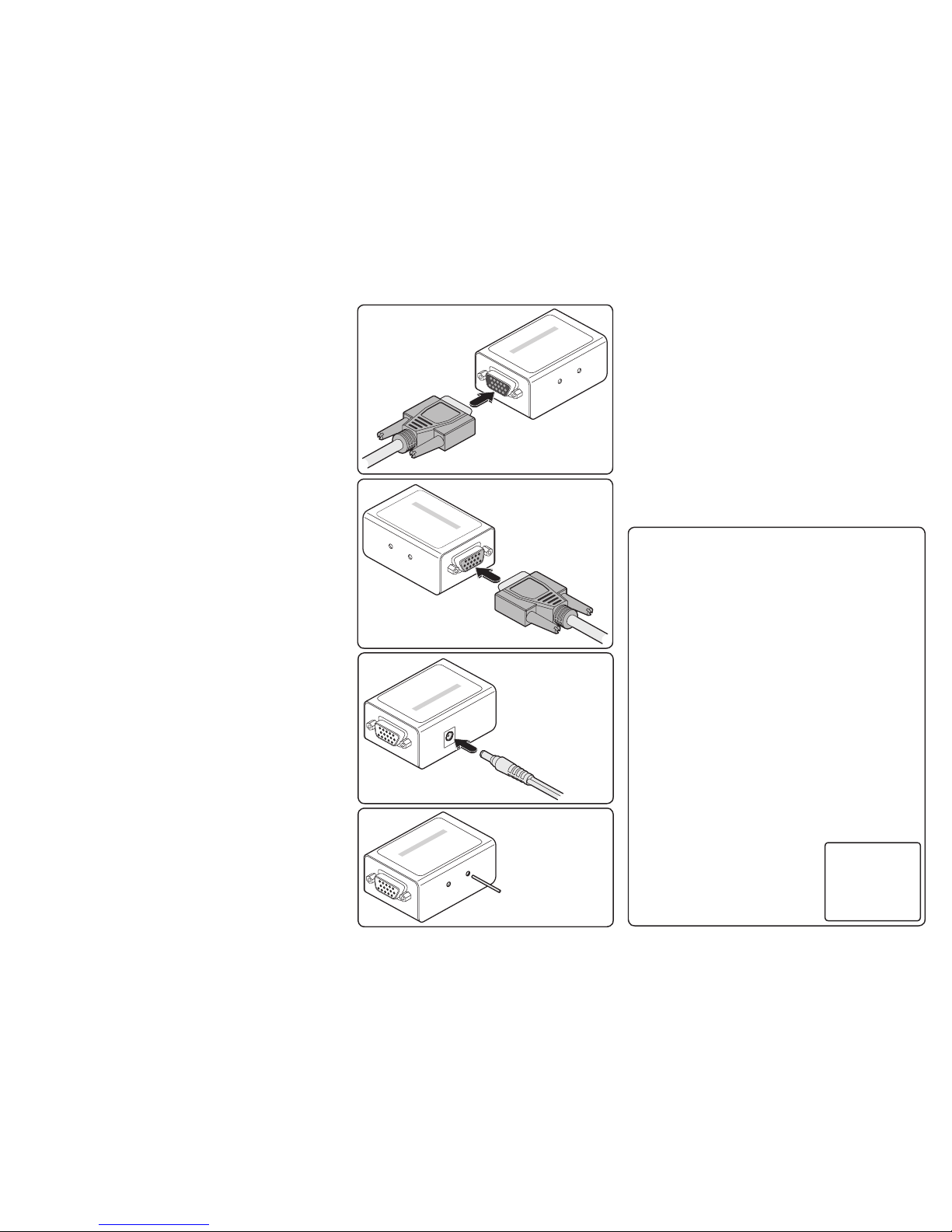
The DDC Ghost module is designed to
attach in-line with a VGA connection
in order to present Extended Display
Identification Data (EDID) to the video
controller independently of the actual
monitor, switch or extender unit. Video
signals are passed straight through the
DDC Ghost.
The Extended Display Identification Data
(EDID) information stored within the DDC
Ghost can either be cloned from a monitor
or used with a standard set of information
(see Standard EDID Information).
D
D
C
G
h
o
s
t
V
G
A
S
T
AT
U
S
C
L
O
N
E
COMPUTER
M
ONIT
OR
EDID
data
V
ideo
signals
Black connector
(to monitor)
Blue connector
(to computer)
Optional
power
input
Control button
and indicator
DDC Ghost
®
NETWORK SERVICES
®
®
NETWORK SERVICES
®
Order toll-free in the U.S.: Call 877-877-BBOX (outside U.S. call 724-746-5500)
FREE technical support 24 hours a day, 7 days a week: Call 724-746-5500 or fax 724-746-0746
Mailing address: Black Box Corporation, 1000 Park Drive, Lawrence, PA 15055-1018
Web site: www.blackbox.com • E-mail: info@blackbox.com
All trademarks acknowledged
Documentation by Corporate Text & Design (www.ctxd.com)
CUSTOMER
SUPPORT
INFORMATION
ACS2100A
DECEMBER 2007
Page 2
DDC
Ghost
VGA
S
T
AT
U
S
C
L
O
N
E
C
O
M
P
U
T
E
R
M
O
N
IT
O
R
Link the computer
to the BLUE
connector
B
Cloning EDID information
The DDC Ghost module contains a default set of EDID values which
may be used immediately with most monitors (see Standard EDID
Information). Alternatively, you can use a ‘donor’ monitor from which
you can clone new EDID information.
To clone EDID information
1 Link the BLACK connector of the DDC Ghost to the donor monitor
(diagram A).
2 Provide power for the DDC Ghost module in one of two ways, either:
• Link the BLUE connector of the DDC Ghost to a computer video
output for the duration of the cloning operation (diagram B), or
• Attach the optional 5VDC power adapter to the socket on the side
of the DDC Ghost module (diagram C).
3 Ensure that the donor monitor and the DDC Ghost module are
powered. The DDC Ghost red STATUS indicator should be on.
4 Using a narrow implement, press and hold the recessed button
labelled CLONE on the side of the module (diagram D). The STATUS
indicator will begin to flash slowly for five seconds. Release the
button while the indicator is still slowly flashing.
• If new EDID information is available, it will be copied to the DDC
Ghost module memory.
• If there is no EDID information to clone then the existing DDC
Ghost memory will be not altered.
• If there is an error during cloning then the DDC Ghost will be
automatically reset to its standard values.
5 When the operation is complete, the STATUS indicator will flash
rapidly five times. Disconnect the DDC Ghost module from the donor
monitor.
Resetting EDID information
If required, you can reinstate the standard EDID values (see Standard
EDID Information) into the DDC Ghost module memory.
To reset the EDID information
1 Ensure that the DDC Ghost is powered (either from the video output
of a host computer or an optional power adapter) and check that the
red STATUS indicator is on.
2 Using a narrow implement, press and hold the recessed button
labelled CLONE on the side of the module (diagram D). The red
STATUS indicator will flash slowly for five seconds and then will go
off for a further five seconds.
3 Release the button while the red STATUS indicator is off, following
the five slow flashes. The reset operation will take place and then
the red STATUS indicator will flash rapidly five times to indicate a
successful completion.
D
D
C
G
h
o
s
t
V
G
A
S
T
AT
U
S
C
L
O
N
E
CO
M
PUTER
MONIT
OR
Link the monitor
to the BLACK
connector
A
D
D
C
G
h
o
s
t V
G
A
S
T
AT
U
S
C
L
O
N
E
COMPUTER
MO
NIT
OR
If power is
unavailable from
the computer via the
BLUE connector, use
the optional 5VDC
power adapter
C
D
D
C
G
h
o
s
t
V
G
A
S
T
AT
U
S
C
L
O
N
E
COMPUTER
MONI
T
OR
Press and hold the
recessed CLONE button.
Release it as follows:
To clone: While
indicator is slowly
flashing.
To reset: While
indicator is off
(immediately following
the slow flashes).
D
Installing for normal operation
During normal operation, the DDC Ghost module supplies either
standardized or cloned EDID information to the computer instead of
the data from the connected monitor.
To install for normal operation
1 Link the BLACK connector of the DDC Ghost to the monitor
(diagram A).
2 Link the BLUE connector of the DDC Ghost to the computer
video output (diagram B)
Note: In operation, the red STATUS indicator should be on. If
it is not then power is not being correctly supplied from the
computer (pin 9 of the VGA connector). If this situation cannot
be resolved, attach the optional 5VDC power adapter to the
socket on the side of the DDC Ghost module (diagram C).
3 Switch on the computer and monitor in the normal manner.
Standard EDID information
The standard EDID information supplied within the DDC
Ghost module represents a standard analogue monitor
(with no manufacturer details) capable of resolutions up to
1600x1200@60Hz. Other presented information is as follows:
Manufacturer details
ID Manufacturer Name: NON
Product ID Code: 0000
Last 5 Digits of Serial Number: 00000
Week of Manufacture: 00
Year of Manufacture: 1990
Complete Serial Number: 0000000000
Video input definition
Analog Signal: 0.700, 0.300 (1.000 Vp-p)
Separate Syncs
Established timing I
720 X 400 @ 70Hz (IBM,VGA)
640 X 480 @ 60Hz (IBM,VGA)
640 X 480 @ 75Hz (VESA)
800 X 600 @ 60Hz (VESA)
Established timing II
800 X 600 @ 75Hz (VESA)
1024 X 768 @ 60Hz (VESA)
1024 X 768 @ 75Hz (VESA)
1280 X 1024 @ 75Hz (VESA)
Standard timing identification
1280 X 1024 @60Hz
1600 X 1200 @60Hz
1152 X 864 @75Hz
Note: The DDC
Ghost module has
the capacity to store
one standard EDID
data block plus one
extension block.
 Loading...