

Black Box ACR9005A, ServSwitch ACR9002A,ServSwitch ACR9004A,ServSwitch ACR9005A, ACR9002A, ACR9004A User Manual
Page 1

THE SERVSWITCH ™ FAMILY
1
Welcome to the ServSwitch™ Family!
Thank you for purchasing a BLACK BOX® ServSwitch™ brand KVM remote
access product. We appreciate your business, and we think you’ll appreciate the
many ways that your new ServSwitch product will save you money, time, and
effort.
That’s because our ServSwitch family is all about breaking away from the
traditional, expensive model of computer management. You know, the one-sizefits-all-even-if-it-doesn’t model that says, “One computer gets one user station, no
more, no less.” Why not a single user station (monitor, keyboard, and mouse) for
multiple computers—even computers of different platforms? Why not a pair of user
stations, each of which can control multiple computers? Why not multiple user
stations for the same computer?
With our ServSwitch products, there’s no reason why not. We carry a broad line
of robust solutions for all these applications. Do you have just two PCs, and need
an economical alternative to keeping two monitors, keyboards, and mice on your
desk? Or do you need to share dozens of computers, including a mix of IBM® PC,
RS/6000®, Apple® Macintosh®, Sun Microsystems®, and SGI® compatibles among
multiple users with different access levels? Does your switch have to sit solidly on
a worktable and use regular everyday cables? Or does it have to be mounted in an
equipment rack and use convenient many-to-one cables? No matter how large or
small your setup is, no matter how simple or how complex, we’re confident we
have a ServSwitch system that’s just right for you.
The ServSwitch™ family from Black Box—the one-stop answer for all your KVMswitching needs!
*
This manual will tell you all about your new ServSwitch Remote™ and ServSwitch
Ultra Remote™, including how to install, operate, and troubleshoot it. For an
introduction to the ServSwitch Ultra Remote, see the introduction section. The
ServSwitch Remote and ServSwitch Ultra Remote product codes covered in this
manual are:
ACR9000A / ACR9002A / ACR9004A / ACR9005A
Page 2

SERVSWITCH ULTRA REMOTE
2
TRADEMARKS USED IN THIS MANUAL
BLACK BOX and the logo are registered trademarks, and ServSwitch, and
ServSwitch Ultra Remote are trademarks, of Black Box Corporation.
Apple, Mac, and Macintosh are registered trademarks of Apple Computer, Inc.
Compaq and Alpha are registered trademarks, and DEC is a trademark, of
Compaq Computer Corporation.
HP is a registered trademark of Hewlett-Packard.
IBM, PC/AT, PS/2, RS/6000, and ThinkPad are registered trademarks, and PC/XT
is a trademark, of International Business Machines Corporation.
Microsoft, HyperTerminal, IntelliMouse, Windows, and Windows NT are registered
trademarks or trademarks of Microsoft Corporation in the United States and/or
other countries.
Sun and Sun Microsystems are registered trademarks of Sun Microsystems, Inc. in
the United States and other countries.
Any other trademarks mentioned in this manual are acknowledged to be the property of the
trademark owners
Page 3
FCC/IC STATEMENTS, EU DECLARATION OF CONFORMITY
3
FEDERAL COMMUNICATIONS COMMISSION AND INDUSTRY CANADA
RADIO-FREQUENCY INTERFERENCE STATEMENTS
This equipment generates, uses, and can radiate radio frequency energy and if not
installed and used properly, that is, in strict accordance with the manufacturer’s
instructions, may cause interference to radio communication. It has been tested
and found to comply with the limits for a Class B computing device in accordance
with the specifications in Subpart B of Part 15 of FCC rules, which are designed to
provide reasonable protection against such interference when the equipment is
operated in a commercial environment. Operation of this equipment in a residential
area is likely to cause interference, in which case the user at his own expense will
be required to take whatever measures may be necessary to correct the
interference.
Changes or modifications not expressly approved by the party responsible for
compliance could void the user’s authority to operate the equipment.
EUROPEAN UNION DECLARATION OF CONFORMITY
This equipment complies with the requirements of the European
EMC Directive 89/336/EEC with respect to EN55022 (Class B),
EN50082-1/EN60555-2 and the Low Voltage Directive.
CE
NOM STATEMENT
Page 4

SERVSWITCH ULTRA REMOTE
4
NORMAS OFICIALES MEXICANAS (NOM)
ELECTRICAL SAFETY STATEMENT
INSTRUCCIONES DE SEGURIDAD
1. Todas las instrucciones de seguridad y operación deberán ser leídas
antes de que el aparato eléctrico sea operado.
2. Las instrucciones de seguridad y operación deberán ser guardadas para
referencia futura.
3. Todas las advertencias en el aparato eléctrico y en sus instrucciones de
operación deben ser respetadas.
4. Todas las instrucciones de operación y uso deben ser seguidas.
5. El aparato eléctrico no deberá ser usado cerca del agua—por ejemplo,
cerca de la tina de baño, lavabo, sótano mojado o cerca de una alberca,
etc.
6. El aparato eléctrico debe ser usado únicamente con carritos o pedestales
que sean recomendados por el fabricante.
7. El aparato eléctrico debe ser montado a la pared o al techo sólo como
sea recomendado por el fabricante.
8. Servicio—El usuario no debe intentar dar servicio al equipo eléctrico más
allá a lo descrito en las instrucciones de operación. Todo otro servicio
deberá ser referido a personal de servicio calificado.
9. El aparato eléctrico debe ser situado de tal manera que su posición no
interfiera su uso. La colocación del aparato eléctrico sobre una cama,
sofá, alfombra o superficie similar puede bloquea la ventilación, no se
debe colocar en libreros o gabinetes que impidan el flujo de aire por los
orificios de ventilación.
10. El equipo eléctrico deber ser situado fuera del alcance de fuentes de
calor como radiadores, registros de calor, estufas u otros aparatos
(incluyendo amplificadores) que producen calor.
11. El aparato eléctrico deberá ser connectado a una fuente de poder sólo
del tipo descrito en el instructivo de operación, o como se indique en el
aparato.
Page 5

NOM STATEMENT
5
12. Precaución debe ser tomada de tal manera que la tierra fisica y la polarización
del equipo no sea eliminada.
13. Los cables de la fuente de poder deben ser guiados de tal manera que no
sean pisados ni pellizcados por objetos colocados sobre o contra ellos,
poniendo particular atención a los contactos y receptáculos donde salen del
aparato.
14. El equipo eléctrico debe ser limpiado únicamente de acuerdo a las
recomendaciones del fabricante.
15. En caso de existir, una antena externa deberá ser localizada lejos de las
lineas de energia.
16. El cable de corriente deberá ser desconectado del cuando el equipo no sea
usado por un largo periodo de tiempo.
17. Cuidado debe ser tomado de tal manera que objectos liquidos no sean
derramados sobre la cubierta u orificios de ventilación.
18. Servicio por personal calificado deberá ser provisto cuando:
A. El cable de poder o el contacto ha sido dañado; u
B. Objectos han caído o líquido ha sido derramado dentro del aparato; o
C. El aparato ha sido expuesto a la lluvia; o
D. El aparato parece no operar normalmente o muestra un cambio en su
desempeño; o
E. El aparato ha sido tirado o su cubierta ha sido dañada.
Page 6

SERVSWITCH ULTRA REMOTE
6
Safety Instructions
The ServSwitch Remote and ServSwitch Ultra Remote have been tested for
conformance to safety regulations and requirements, and has been certified for
international use. Like all electronic equipment, the ServSwitch Remote and
ServSwitch Ultra Remote should be used with care. To protect yourself from
possible injury to minimize the risk of damage to the ServSwitch Remote or
ServSwitch Ultra Remote and other equipment, read and follow these safety
instructions.
Caution!
If the battery on the ServSwitch Remote or ServSwitch Ultra
Remote’s motherboard fails, do not attempt to replace it yourself
unless you are directed to do so by a Black Box technician. If
you are directed to replace it, make sure to use the proper type of
battery. Using the wrong type of battery creates the risk of a fire
or small-scale explosion. Dispose of used batteries according to
the battery manufacture’s instructions. Follow all instructions
and warnings marked on the ServSwitch Remote and ServSwitch
Ultra Remote.
• Do not attempt to service the ServSwitch Remote and ServSwitch Ultra
Remote yourself.
• Do not use the ServSwitch Remote and ServSwitch Ultra Remote near water.
• Place the ServSwitch Remote and ServSwitch Ultra Remote only on a stable,
clean, dry, flat surface or in a 19” equipment rack.
• Provide proper ventilation and air circulation for the ServSwitch Remote and
ServSwitch Ultra Remote.
• Keep the ServSwitch Remote and ServSwitch Ultra Remote’s power cord and
attached cables clear of obstructions that might cause damage to them.
• Use only power cords, power transformer and connection cables designed got
this unit.
• Keep liquids and potentially damaging objects away for the ServSwitch
Remote and ServSwitch Ultra Remote. Liquids and foreign objects might
come in contact with voltage points, which could create a risk of fire or
electrical shock.
• Operate the ServSwitch Remote and ServSwitch Ultra Remote only when the
cover of its enclosure is in place.
• Do not use liquid or aerosol cleaners to clean the ServSwitch Remote or
ServSwitch Ultra Remote. Always unplug the ServSwitch Remote or
ServSwitch Ultra Remote from its electrical outlet before cleaning it.
Page 7

SAFETY INSTRUCTIONS
7
• Immediately unplug the ServSwitch Remote or ServSwitch Ultra Remote from
its electrical outlet and call Black Box to arrange for service if any of the
following conditions occur:
- The power cord or attached cables have become damaged or frayed.
- The ServSwitch Remote or ServSwitch Ultra Remote has been exposed
to a liquid
- The ServSwitch Remote or ServSwitch Ultra Remote does not operate
normally when all operating instructions have been followed.
- The ServSwitch Remote or ServSwitch Ultra Remote has been dropped
or its case has been damaged.
- The ServSwitch Remote or ServSwitch Ultra Remote begins performing
poorly.
Disclaimer
While every precaution has been taken in the preparation of this manual, the
manufacturer assumes no responsibility for errors or omissions. Neither does the
manufacturer assume any liability for damages resulting from the use of the
information contained herein. The manufacturer reserves the right to change the
specifications, functions, or circuitry of the product without notice.
The manufacturer cannot accept liability for damages due to misuse
of the product or other circumstances outside the manufacturer’s control. The
manufacturer will not be responsible for any loss, damage, or injury arising directly
or indirectly from the use of this product.
Page 8

SERVSWITCH ULTRA REMOTE
8
Contents
Chapter Page
1. Quick Start Guide..................................................................................................10
2. Specifications.........................................................................................................15
3. Introduction .........................................................................................................17
3.1 Overview...........................................................................................................17
3.2 Features...........................................................................................................18
4. Getting Started.......................................................................................................19
4.1 Package contents.............................................................................................19
4.2 Other items needed..........................................................................................19
5. Hardware Installation.............................................................................................20
5.1 Hardware Installation (Model ACR9000A)......................................................20
5.2 Hardware Installation.......................................................................................22
(Model ACR9002A, ACR9004A, ACR9005A).......................................................22
6. Initial Power-up and Configuration.......................................................................25
6.1 Powering up the models..................................................................................25
6.2 Configuring the unit..........................................................................................28
6.3 The configuration screen.................................................................................28
7. Installing and configuring the Viewer Software....................................................30
7.1 System requirements.......................................................................................30
7.2 Installing the Viewer software..........................................................................30
7.3 Connection screen...........................................................................................33
7.4 Keyboard and mouse screen...........................................................................34
8. Viewer Features ....................................................................................................38
9. Operation .........................................................................................................45
9.1 Connecting........................................................................................................45
10. Service and maintenance information.................................................................49
11. Trouble Shooting..................................................................................................50
12. Appendices .........................................................................................................51
Page 9

TABLE OF CONTENTS
9
Figures
Figure Page
Figure 1.1 Model ACR9000A.....................................................................................10
Figure 1.1.1 All other models.....................................................................................10
Figure 1.2 Configure unit............................................................................................11
Figure 1.3 Set-up Wizard ...........................................................................................12
Figure 1.4 Change default name...............................................................................13
Figure 1.5 Remote video displayed in the Viewer....................................................14
Figure 5.1 Model ACR9000A cabling........................................................................20
Figure 5.1.1 Model ACR9000A cabling.....................................................................21
Figure 5.2 Model ACR9002A cabling ........................................................................22
Figure 5.3 Model ACR9004A cabling........................................................................23
Figure 5.4 Model ACR9005A cabling........................................................................24
Figure 6.1 Connect login screen................................................................................25
Figure 6.2 Invalid mode screen.................................................................................26
Figure 6.3 Configure login screen..............................................................................27
Figure 6.4 Configure screen.......................................................................................28
Figure 7.1 Viewer installation wizard.........................................................................31
Figure 7.2 Viewer screen...........................................................................................32
Figure 7.3 Connection screen....................................................................................33
Figure 7.4 Keyboard and mouse settings.................................................................34
Figure 7.5 Login screen..............................................................................................36
Figure 7.6 User details ...............................................................................................37
Figure 8.1 Viewer window..........................................................................................38
Figure 8.2 KVM switch menu.....................................................................................43
Figure 9.1 Connection (PC / Switch).........................................................................46
Figure 9.2 Quad screen mode..................................................................................47
Tables
Tabel Page
Table 8.1 Icon description..........................................................................................38
Appendices
Appendix Page
Appendix A. Part numbers.........................................................................................51
Appendix B. RackMount.............................................................................................52
Appendix C. KeyCodes..............................................................................................53
Appendix D. Import file format ...................................................................................53
Appendix E. ServSwitch Ultra Remote firmware upgrade........................................55
Appendix F. Viewer software upgrade......................................................................56
Page 10

SERVSWITCH ULTRA REMOTE
10
1. Quick Start Guide
This quick installation procedure for the ServSwitch Remote and ServSwitch Ultra
Remote assumes that:
§ You have an active Ethernet TCP/IP network
§ You have a PC on the network to install the Viewer software.
§ You are connecting the ServSwitch Remote or ServSwitch Ultra Remote to a
standalone computer or KVM switch.
Refer to chapter 4.0 for a more detailed procedure for installation and configuration
procedures.
1. Connect your equipment to the ServSwitch Remote or ServSwitch Ultra
Remote:
(Note: Cable connection for model ACR9000A are shown in Figure 1.1.
Models ACR9002A, ACR9004A, and ACR9005A are shown in Figure 1.1.1)
§ Temporarily connect a local keyboard, monitor, and mouse to the
corresponding connectors on the rear panel of the ServSwitch Remote as
shown in Figure 1.1 or 1.2.
§ Connect a network cable from your Ethernet hub, router, or switch to the
corresponding network connector on the rear panel of the ServSwitch
Remote as shown in Figure 1.1 or 1.1.1
§ Connect a standalone computer or KVM switch to the corresponding
DB25F connector as shown in Figure 1.1 or 1.1.1.
- Use the included DB25M to DB25M to connect to the MKM ports on a
compatible ServSwitch family KVM switch
- Use the included DB25M to HD15/PS2/PS2 (3-to-1) cable to connect
to the keyboard, monitor, and mouse ports on a standalone
computer.
Figure 1.1 Model ACR9000A Figure 1.1.1 All other models
Page 11

CHAPTER 1: Quick Start Guide
11
2. Configure the IP address:
A unique IP address must be assigned to each unit locally from the connected
KVM station. Model ACR9000A and ACR9005A (single models) assign one IP
address. Model ACR9002A assign two IP addresses (dual), and model
ACR9004A (quad) is assigned four IP addresses.
• Apply power to the unit and the startup screen will display on the local KVM
monitor. Wait until the “Connect login” screen (green background) appears.
• DO NOT LOGON to the “Connect login” screen, press [F10] to bring-up the
“Configure login” screen (gray background)
• Enter the user-ID ‘admin” with no password, the configure screen will
display (see Figure 1.2)
SERVSWITCH REMOTE VERSION 1.35 COPYRIGHT 2004 BLACK BOX CORPORATION
Configuration
IP address 192.168.0.99
Subnet mask 255.255.255.0
Gateway
TCP port 5678
Speed/duplex
Com1
Com2
Auto
None
none
Enter the new network setting
in the typical dotted notation
by keying in the value.
IP address, subnet mask and
gateway are standard TCP/IP
settings. They become effective
immediately upon save and exit.
TCP port specifies a number used
to listen for connections from
the Viewer program, which must be
configured with the same number.
Use 5678 unless otherwise
required.
Set Speed/duplex to Auto unless
you are connecting to a device
which requires a fixed speed or
duplex setting.
?? Select item
F9-Exit without saving
F10- Save and exit
Figure 1.2 Configure unit
§ Using the up/down arrow keys, select IP address and enter the assigned
network IP address for this unit
§ Select and enter the Subnet mask, optional gateway address, TCP port (if
you system requires a different value than 5678), and Speed/duplex. It is
recommended that the default setting of “Auto” be used unless your system
requires a specific speed and duplex value
§ Com1 and Com2 are reserved for future enhancements to the unit which will
allow for dial-up capabilities
§ When all network values have been entered, press [F10] to save the network
information and exit
Next, install the Viewer software on the network workstations.
Page 12
SERVSWITCH ULTRA REMOTE
12
3. Installing the Viewer program on a network PC:
The ServSwitch Remote and ServSwitch Ultra Remote come with two Viewer
software diskettes.
• Insert diskette #1 into a network PC workstation with the following minimum
requirements:
• 133-MHz IBM compatible PC with 32 MB of system memory and 4MB of
free disk space
• VGA display adapter and monitor capable of 640 x 480 resolution
• Keyboard and mouse
• Network connection with TCP/IP protocol
• Microsoft Windows 95 or later Windows operating system
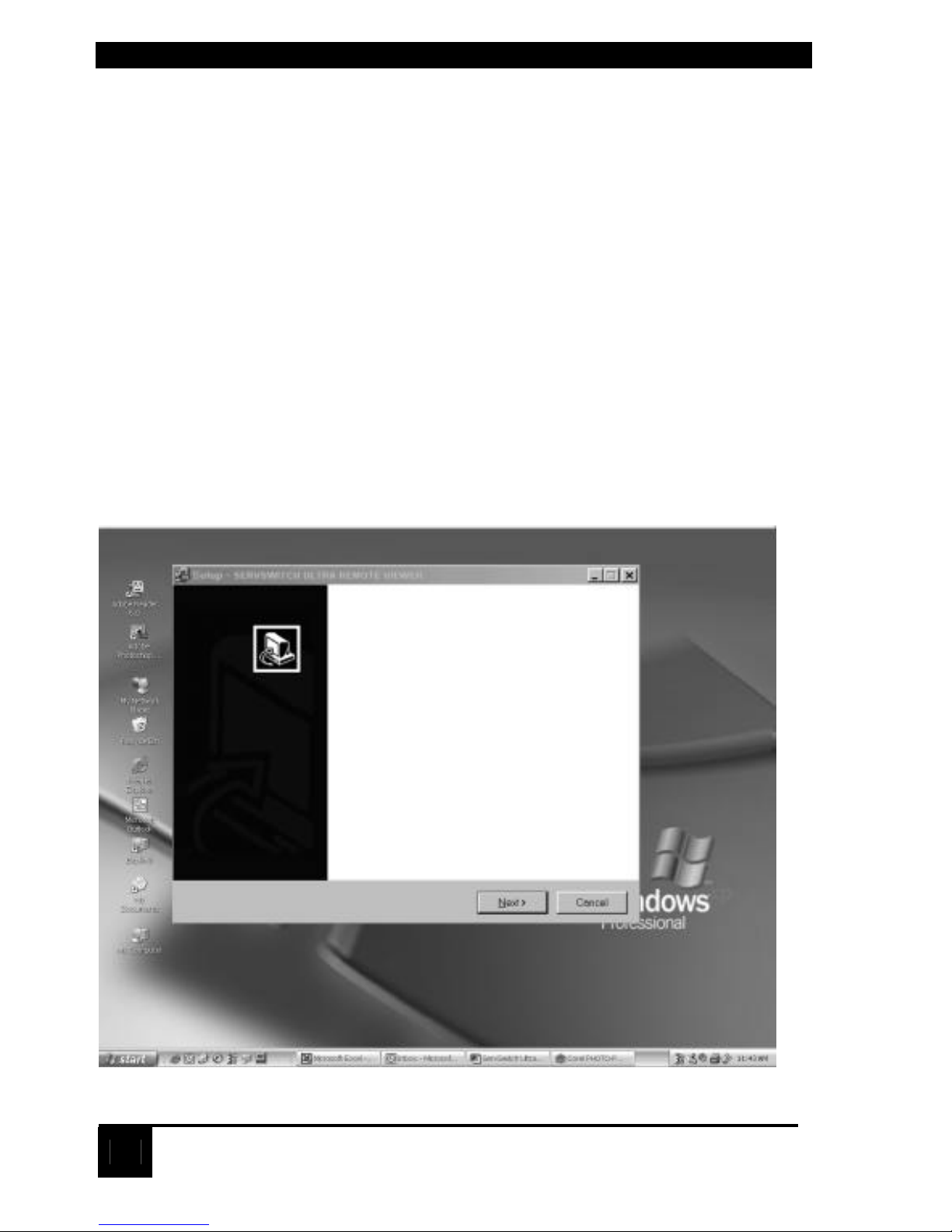
• Run the “Setup” program on the diskette. You’ll be guided through a
standard Windows style installation process as shown in Figure 1.3
• Click through to specify the installation directory and whether you want the
associated start-menu folder, desktop and quick-launch icons
• Insert diskette #2 when requested
• Read the “Readme” file on the diskette for late-breaking developments.
Figure 1.3 Set-up Wizard
Welcome to the ServSwitch
Ultra Remote Viewer Setup
Wizard
This will install ServSwitch Ultra Remote Viewer on your
computer.
It is strongly recommended that you close all other
applications you have running before continuing. This will help
prevent any conflicts during the installation process.
Click Next to continue, or Cancel to exit setup
Page 13

CHAPTER 1: Quick Start Guide
13
4. Configuring the viewer with the ServSwitch Ultra Remote’s IP address
• Run the Viewer program
• Click on the “Settings”, then the “Connections” tab and use “Edit Location” to
change “Default” to a name of your choosing (Figure 1.4)
• Change the IP address to the one assigned to the unit in step 2
(Use the default TCP port value of 5678 unless it was changed in step 2)
• Click OK and the new location name will appear on the toolbar
• For additional information about the Viewer, click on Help
Figure 1.4 Change default name
Proceed to step 5 to make a connection
Page 14

SERVSWITCH ULTRA REMOTE
14
5. Make a connection
• Press the connect icon (second from the left in the viewer toolbar) or
click on “Connect” in the pull-down connect menu. The login screen should
appear.
• Enter the user ID ‘admin” and no password. Once validated, the video
output of the computer connected to the ServSwitch Ultra Remote or KVM
switch will display. An example is shown in Figure 1.5.
• The pass through message box should appear. Click OK to pass the local
keyboard and mouse commands to the remote computer or switch
• Press [Ctrl] [Alt] [P] to exit the pass through mode and apply the keyboard
and mouse commands to your workstation. Rapidly moving the mouse will
also exit the pass through mode.
• Refer to the detailed Viewer screen section to customize the viewer screens,
add users, change the default “admin” user ID and password, and other
viewer features.
Figure 1.5 Remote video displayed in the Viewer
Page 15

CHAPTER 2: Specifications
15
2. Specifications
Hardware
Required -
Monitor that is compatible with the highest video
standard of any connected computer. Multiplatform
applications should use a multi-sync mode.
Compliance - CE, FCC, UL, cUL, TCV, VCCI
Standards - VGA, SVGA, or XGA video from directly attached
computer.
Mac®, Sun, RS/6000®, or SGI™ video can be displayed
if connected to a KVM switch.
Interfaces - To KVM switch or CPU; Proprietary composite of IBM
PS/2 keyboard and mouse and VGA, SVGA, XGA
video
Network; 10/100BASE-T Ethernet;
VGA IN/OUT; VGA, SVGA, XGA
To keyboard and mouse; IBM PS/2 type;
Serial; (Reserved for future enhancements)
USB; (Reserved for future enhancements)
Resolution and
Refresh Rate -
Up to 1280 x 1024 non-interlaced @ 75Hz
Video Bandwidth -
150 MHz
Maximum
Distance -
Network workstation through TCP/IP – no limitation
Local keyboard, monitor, mouse – 20ft. (6.1m)
Attached CPU or KVM switch – 20 ft. (6.1m)
Indicators - Front-mounted LEDs
Power (AC power indicator)
NET (TCP/IP user logged in)
Serial (Reserved for future enhancements)
LOCAL (Local user logged in)
Connectors - CPU/Switch – DB25F
Ethernet port – RJ45
Monitor – HD15F
PS/2 Keyboard / Mouse – MiniDIN-6F
Serial – DB9M (Reserved)
USB – Type A (Reserved)
Power – IEC320
Page 16

SERVSWITCH ULTRA REMOTE
16
Power -
Auto-switching 90 – 240 VAC, 50/60 Hz
Maximum
Altitude -
10,000ft. (3048 m)
Operating
Temperature -
32°F - 113°F ( 0°C - 45°C)
Humidity - 5% - 80% non-condensing
Enclosure - Electro-galvanized steel
Size - ACR9000A – 1.75”H x 16.7”W x 9.7”D (4.4x42.4x24.6 cm)
ACR9002A – 1.75”H x 16.7”W x 9.7”D (4.4x42.4x24.6 cm)
ACR9004A – 3.50”H x 16.7”W x 9.7”D (8.9x42.4x24.6 cm)
ACR9005A – 1.75”H x 8.90”W x 8.4”D (4.4x21.3x22.6 cm)
Weight - ACR9000A – 8.0 lbs (3.6 kg)
ACR9002A – 9.0 lbs (4.1 kg)
ACR9004A – 11.0 lbs (5.0 kg)
ACR9005A – 4.1 lbs (1.86 kg)
Page 17

CHAPTER 3: Introduction
17
3. Introduction
3.1 Overview
The ServSwitch Remote and Ultra Remote are powerful products that extends the
range of access to your computers to anywhere in the world. Its advanced design
makes it compatible with most IBM PC compatible computers and with industrystandard KVM switches. It is most commonly used to extend a KVM switch’s user
port to be accessed through a LAN connection (or, in the future, a dialup/WAN
connection).
Installation of the ServSwitch Remote or ServSwitch Ultra Remote consists of two
easy and straightforward processes, connect the hardware, and install the Viewer
program on a windows workstation on the network.
First connect the unit to your Ethernet network, connect a local keyboard, monitor,
and mouse, and connect to a standalone computer or KVM switch. Next power on
the unit and login; display the configuration screen and enter the assigned IP
address and network information for this unit; and save the configuration
information. That completes the basic unit installation procedure.
The model ACR9002A consists of two independent modules in a single chassis.
Each module must be assigned a unique IP address and network information. For
this model, connect the local keyboard, monitor, mouse, and computer or KVM
switch to the second module and configure its network information. Model ACR
9004A has four independent modules in a single chassis. Each of these modules
must be assigned a unique IP address and network information.
When the unit has its network information entered and saved, install and configure
the Viewer program on a network workstation.
The Viewer provides secure, encrypted access from a network workstation to the
ServSwitch Remote or ServSwitch Ultra Remote. The Viewer’s installation wizard
provides easy instructions on installing the Viewer. Once installed, the IP address
assigned to the ServSwitch Remote or ServSwitch Ultra Remote is entered into the
Viewer settings.
Click on the connect icon , enter the assigned user ID and password and you
will be connected to the unit and the connected computer’s video will display in the
Viewer’s window. The Viewer is in the pass-through mode, meaning all keyboard
and mouse commands now applied to the remote connection. To regain control
and apply the keyboard and mouse commands to your workstation, press the left
[Ctrl], [Alt], and [P] keys. Keyboard and mouse commands now apply to your
workstation. To re-enter the pass-through mode, place the mouse anywhere in the
Viewer’s window and click the left mouse button.
Page 18

SERVSWITCH ULTRA REMOTE
18
3.2 Features
• Connect to a remote computer, server, or KVM switch directly, over a network,
or, in the future, by dial-up
• Available in different models, single, dual or quad versions
• Local KVM port for configuring unit and local access to the computer/switch
• Resolution up to 1280 x 1024 @ 85Hz
• Solid-state embedded unit has no disk drive for maximum reliability
• Compatible with many ServSwitch family KVM products and other KVM
devices
• Scaling of computer images reduces the amount of data sent and permits fast
screen updates over slow links
(Modes: scaled, scrolled, or full-screen)
• Quad screen mode allows you to view four servers from one screen
• Password security prevents unauthorized Unit and Viewer configuration
• User ID and password required for remote access
• Remote client application is simple to install, use, and requires no client
licensing
• Dial-up capability with dial-back feature for added security
(future enhancement)
• Front panel shows power and currently connected input port (Network, serial,
or local KVM)
• Flash memory technology
• Easy to install
• 1U high chassis for model ACR9000A, ACR9002A, and ACR9005A;
2U high chassis for the ACR9004A model.
Page 19

CHAPTER 4: Getting Started
19
4. Getting Started
4.1 Package contents
Model
Contents ACR9000A ACR9002A ACR9004A ACR9005A
6 ft (1.8m)
Power cord
(1) (1) (1) (1)
5 ft (1.9m)
DB25M to DB25M cable
(1) (2) (4) (1)
5 ft (1.9M)
DB25M to HD15-PS/2-PS/2
(1) (2) (4) (1)
1 ft.(0.3m)
HD15M to HD15M
(1) N/A N/A N/A
3.5” Installation Diskettes
(Viewer program)
(2) (2) (2) (2)
Rack mount hardware
(brackets / screws)
(2 / 4) (2 / 4) (4 / 8) (2 / 4)
number in brackets (n) indicates quantity
4.2 Other items needed
The following items are needed to complete the connections and use your
ServSwitch Remote or ServSwitch Ultra Remote:
• RJ-45 network cable
• Standalone computer or KVM switch to be viewed and accessed
• Active TCP/IP network
• Workstation, running Windows, connected to the network to act as the Viewer
• PC keyboard (PS/2 connector)
• PS/2 Mouse (Optional)
• VGA monitor
Page 20

SERVSWITCH ULTRA REMOTE
20
5. Hardware Installation
NOTE
This product is not intended for connection to circuits
carrying telecommunication-network voltages (TNV)
This section provides detailed instructions for installing the hardware and cabling
for all models. The hardware installation will vary slightly depending on the model
being installed. Refer to following sections for the hardware installation procedure
for your model:
• Section 5.1 for model ACR9000A
• Section 5.2 for models ACR9002A, ACR9004A, and ACR9005A
5.1 Hardware Installation (Model ACR9000A)
Model ACR9000A can be installed one of two ways, with local KVM access and
without local KVM access. If you do not need local access to your computer or
switch, the KVM station can be removed once the unit has been configured with its
network information.
To connect the unit for initial configuration and no local KVM access, connect the
cables as shown in Figure 5.1, or with local KVM access as shown in Figure 5.1.1.
Figure 5.1 Model ACR9000A cabling (temporary local access for configuration,
keyboard, monitor, and mouse can be removed during normal operation.
MOUSE
MONITOR
SWITCH/CPU
NETWORK
Page 21

CHAPTER 5: Hardware Installation
21
Figure 5.1.1 Model ACR9000A cabling for permanent local KVM access
connection (Video loop-back cable installed)
Perform the following steps to install the hardware on your ServSwitch Remote or
ServSwitch Ultra Remote:
1. Assure that power is off on the unit and connect the included power cord
from the unit’s IEC320 power connector to an AC power outlet.
2. Connect a network cable, configured with RJ45 connectors, from the
network port on the unit to a hub, router, network switch, or other Ethernet
device.
3. Connect a local PS/2 keyboard and mouse to the corresponding 6-pin
mini-DIN keyboard and mouse ports on the unit.
4. Connect a monitor to the unit as shown in Figure 5.1 (Temporary KVM
access) or as shown in Figure 5.1.1 (Permanent KVM access, must also
connect the HD15M to HD15M video loop-back cable)
5. Connect the computer or switch to access to the unit’s DB25F connector
and to the keyboard, monitor, and mouse ports on a computer or to the
KVM input on a switch. Use the included DB25M to HD15M / PS2 / PS2
cable to connect to a computers monitor, keyboard, and mouse ports.
Use the included DB25M to DB25M cable to connect to a KVM switch.
(NOTE: The DB9F serial connectors and USB ports are reserved at this time for
future dial-up and USB support.
KEYBOARD
MOUSE MONITOR NETWORK SWITCH/CPU
VIDEO LOOP
-
BACK CABLE
Page 22

SERVSWITCH ULTRA REMOTE
22
5.2 Hardware Installation
(Model ACR9002A, ACR9004A, ACR9005A)
Models ACR9002A, ACR9004A, and ACR9005A are all installed using the same
procedure. Figure 5.2 shows the cable connections for the ACR9002A model.
Figure 5.3 show the cabling for the ACR9004A model, and Figure 5.4 shows model
ACR9005A cabling.
Figure 5.2 Model ACR9002A ports
Perform the following steps to install the hardware on model ACR9002A:
1. Assure that power is off on the unit and connect the included power cord
from the unit’s IEC320 power connector to an AC power outlet.
2. Connect a network cable, configured with RJ45 connectors, from the
network port on the unit to a hub, router, network switch, or other Ethernet
device.
3. Connect a local PS/2 keyboard and mouse to the corresponding 6-pin
mini-DIN keyboard and mouse ports on the unit.
4. Connect a monitor to the HD15F connector marked MONITOR.
5. Connect the computer or switch to access to the unit’s DB25F connector
and to the keyboard, monitor, and mouse ports on a computer or to the
KVM input on a switch. Use the included DB25M to HD15M / PS2 / PS2
cable to connect to a computers monitor, keyboard, and mouse ports.
Use the included DB25M to DB25M cable to connect to a KVM switch.
6. Connect all cables listed in steps 1-5 for the second module in the unit
(NOTE: The DB9F serial connectors are reserved at this time for dial-up support.)
Page 23

CHAPTER 5: Hardware Installation
23
Figure 5.3 Model ACR9004A ports
Perform the following steps to install the hardware on model ACR9004A:
1. Assure that power is off on the unit and connect the included power cord
from the unit’s IEC320 power connector to an AC power outlet.
2. Connect a network cable, configured with RJ45 connectors, from the
network port on the unit to a hub, router, network switch, or other Ethernet
device.
3. Connect a local PS/2 keyboard and mouse to the corresponding 6-pin
mini-DIN keyboard and mouse ports on the unit.
4. Connect a monitor to the HD15F connector marked MONITOR.
5. Connect the computer or switch to access to the unit’s DB25F connector
and to the keyboard, monitor, and mouse ports on a computer or to the
KVM input on a switch. Use the included DB25M to HD15M / PS2 / PS2
cable to connect to a computers monitor, keyboard, and mouse ports.
Use the included DB25M to DB25M cable to connect to a KVM switch.
6. Connect all cables listed in steps 1-5 for the second module in the unit
7. Connect all cables listed in steps 1-5 for the third module in the unit
8. Connect all cables listed in steps 1-5 for the fourth module in the unit
(NOTE: The DB9F serial connectors are reserved at this time for dial-up support.)
Page 24

SERVSWITCH ULTRA REMOTE
24
Figure 5.4 Model ACR9005A ports
Perform the following steps to install the hardware on model ACR9005A:
1. Assure that power is off on the unit and connect the included power cord
from the unit’s IEC320 power connector to an AC power outlet.
2. Connect a network cable, configured with RJ45 connectors, from the
network port on the unit to a hub, router, network switch, or other Ethernet
device.
3. Connect a local PS/2 keyboard and mouse to the corresponding 6-pin
mini-DIN keyboard and mouse ports on the unit.
4. Connect a monitor to the HD15F connector marked MONITOR.
5. Connect the computer or switch to access to the unit’s DB25F connector
and to the keyboard, monitor, and mouse ports on a computer or to the
KVM input on a switch. Use the included DB25M to HD15M / PS2 / PS2
cable to connect to a computers monitor, keyboard, and mouse ports.
Use the included DB25M to DB25M cable to connect to a KVM switch.
(NOTE: The DB9F serial connectors are reserved at this time for dial-up support.)
This completes the basic hardware cabling for all models. With the cabling in place
each ServSwitch Remote or ServSwitch Ultra Remote must have its network
information entered and saved. Chapter 6 explains in detail the unit configuration.
Page 25

CHAPTER 6: Initial Power-Up and Configuration
25
6. Initial Power-up and
Configuration
6.1 Powering up the models
Powering up the ServSwitch Remote or ServSwitch Ultra Remote for the first
time will require you to login and configure the unit with the needed network
information. When you turn on the unit, the front panel green power LED will
light. If the power LED does not light, turn the power off, check the power
connections, wait at least 15 seconds, and turn the power back on.
When power is applied, the ServSwitch Ultra Remote will perform a self-test and
start-up sequence. When the self-test is complete, the “Connect” login screen will
display as shown in Figure 6.1. The monitor may remain blank for up to 25
seconds before the “Connect” login screen displays.
UltraRemote version 1.35 Copyright 2002-2004 Black Box Corporation
Connect Login
User _
Password
F1-Help F9-Connect F10-Configure
Figure 6.1 Connect login screen
The “Connect” login screen is used to connect to an ServSwitch Ultra Remote
connected to your network. This function will not work until the unit has the
network information entered and saved. Initially, DO NOT login on the “Connect”
login screen. Press the [F10] key to bring up the “Configure” login screen. The
“Connect” and “Configure” login screens are very similar. The “Connect” login
screen has a green background and the “Configure” login screen has a gray
background. Login on the “Configure” login screen (Figure 6.3)
Page 26

SERVSWITCH ULTRA REMOTE
26
If you do not see the video of the connected device or see an invalid mode screen
similar to the example in Figure 6.2, check all the cable connections. Refer to the
troubleshooting section for additional help. This invalid mode screen only applies
to model ACR9000A and will occur when trying to connect to an attached computer
and the loop-back cable is not connected or the KVM station’s monitor is
connected to the wrong video port.
Ultra Remote version 1.35 Copyright 2002-2004 Black Box Corporation
Invalid mode
If you are seeing this screen,
you went into local connect mode
with your monitor connected to
the wrong port on the back of the
Ultra Remote.
To see the video of the local KVM
device, connect the monitor to
the upper HD15 video connector
just to the left of the DB25.
Use the Hd15 loop connector
provided to connect the lower
HD15 video connector and the HD15
connector just to the right of
the upper DB9 connector.
While you are in this invalid
mode your keyboard and mouse are
be
ing sent to the KVM device, but
you can’t see it.
Either connect the video as
described or press alt-Ctrl-
L
to return to the connect
login screen.
Note:
This arrangement allows an
analog connection to the KVM
device. In the future a
digital connection t
o the KVM
device may be implemented in
which case the loop connector
will not be used.
Figure 6.2 Invalid mode screen
Page 27

CHAPTER 6: Initial Power-Up and Configuration
27
UltraRemote version 1.35 Copyright 2002-2004 Black Box Corporation
Configure Login
User _
Password
F1-Help F9-Connect F10-Configure
Figure 6.3 Configure login screen
A default administrator account exists on all models for initial configuration of the
network information and to initially connect to an attached computer or switch. The
default administrator account’s User ID is “admin” and no password.
The network information does not have to be entered and saved for the local
access KVM station to connect to an attached computer. Initially, the administrator
should assure that all cabling is in place and connect locally to a computer or
switch before configuring the unit with its network information. From the “Connect”
login screen, enter the default account user ID of “admin” with no password and
press [Enter]. If the connected computer of switch is powered on, you should see
the connected computers video. Verify that the video is ok and the keyboard and
mouse perform properly.
To exit and return to the connect login screen, press the [Ctrl], [Alt], and [L] key
simultaneously and the “Connect” login screen will display.
To configure the ServSwitch Remote or ServSwitch Ultra Remote, from the
“Connect” login screen, press [F10] to display the “Configure” login screen.
Page 28

SERVSWITCH ULTRA REMOTE
28
6.2 Configuring the unit
When you login on the “Configure” login screen, the user ID and password are
validated, and if confirmed, the configure screen will display (Shown in Figure 6.4.)
Ultra Remote version 1.35 Copyright 2000-2004 Black Box Corporation
Configure Login
IP address 192.168.255.255
Subnet mask 255.255.0.10
Gateway 192.168.0.10
TCP port 5678
Speed/duplex Auto
Com 1 None
Com 2 None
Enter the new network settings
in the typical dotted nota
tion
by keying in the value.
IP address, subnet mask and gateway
are the standard TCP/IP settings.
They become effective immediately
upon save and exit.
TCP port specifies a number used to
listen for connection from the
viewer program, which must be configured with the same number. Use
5678 unless otherwise required.
Set Speed/duplex to Auto unless you
are connecting to a device which
requires a fixed speed or duplex
setting.
Select a device for Serial 1 and/or
Serial 2 to receive viewer calls.
Select item F9–Exit without saving
F10–save and exit
Figure 6.4 Configure screen
6.3 The configuration screen
Using the up/down arrow keys, select and enter the assigned IP address, subnet
mask, Gateway (optional), and the TCP port number. Use the default value of
5678 for the TCP port value unless otherwise required. Use the default value of
Auto for the Speed / duplex value unless your network requires a specific speed
and duplex value. When you select the Speed / duplex field, press the page up
key to list the speed and duplex options. Select the option that matches your
network.
Com 1 and Com 2 are reserved for future dial-up capability.
NOTE: The IP address and TCP port value must also be entered into
the Viewer program .
Page 29

CHAPTER 6: Initial Power-Up and Configuration
29
Enter the following configure login parameters for this product. Use the up/down
arrow keys to select;
1. IP address
2. Subnet mask
3. Gateway (optional)
4. TCP port (use default of 5678 if no specific TCP port is required)
5. Speed/duplex (use page up/page down keys to display Speed/duplex options)
6. Com 1 (Reserved for future enhancements)
7. Com 2 (Reserved for future enhancements)
The Gateway value is optional. Use the default value of 5678 for the TCP port
unless otherwise required. The TCP port value must also be entered into the
Viewer program if changed from 5678. Also, use the default value of Auto for the
Speed / duplex value unless otherwise required.
When all values have been entered on the configure screen, press the F10 key to
save the values and exit. The values entered will be saved and the “Connect
Login” screen will display.
Page 30

SERVSWITCH ULTRA REMOTE
30
7. Installing and configuring
the Viewer Software
7.1 System requirements
Two Viewer software diskettes are included with your unit. The Viewer program
can be installed on any Windows based PC connected to your network. The
minimum PC requirements for installing the Viewer are:
• 133-MHz IBM compatible PC
• 32 MB of system memory
• 4 MB of free disk space
• VGA display adapter
• Monitor capable of 640 x 480 resolution
• Network connection with TCP/IP protocol
• Microsoft Windows 95 or higher operating system
7.2 Installing the Viewer software
To install the Viewer software, perform the following steps. It is recommended that
you close all workstation applications before installation. If you are upgrading
existing Viewer software or the Units firmware, please refer to Appendix E & F for
upgrade instructions.
1. Insert the Setup diskette (Diskette #1) and click Start, run, type in A:\Setup.exe
in the “Open” input field, click OK.
The setup wizard will display. (Figure 7.1)
2. Click “Next” to begin the installation process. Read the “License agreement” and
click “Yes” to continue.
3. Enter the “Destination directory” if different than the default (C:\Program
Files\ServSwitch Ultra Remote Viewer) and click “Next”
4. Enter the “Start menu” folder name if different from the default name
(ServSwitch Ultra Remote Viewer) and click “Next”.
5. Two additional tasks can be performed during installation, create a quick launch
icon and create a desktop icon
6. Check or un-check the choice boxes for the icon’s wanted and click “Next”
7. A final screen will display. Verify that the “Destination directory”, the “Start
menu” folder, and the “Create Icon” choices are correct and click “Install”. Click
“Back” to correct any information that has been entered incorrectly
8. The installation process will begin. Insert Disk 2 when prompted. When the final
installation process is completed, the finish screen will display. Check the
“Launch ServSwitch Ultra Remote Viewer” box
9. Click on “Finish” to complete the installation process and launch the Viewer
Page 31

CHAPTER 7: Viewer Software
31
Figure 7.1 Viewer installation wizard
Please note the following important items concerning using the Viewer for the first
time.
Pass-through mode
When logging in to any unit from the Viewer for the first time, use the default
administrator account User ID “admin” and no password. Once logged in, the
Viewer is in the “Pass-through” mode. In this mode, all keyboard and mouse
activity is passed to the ServSwitch Remote. There are no keyboard or mouse
functions available for the workstation the Viewer is installed on. To exit the “Passthrough” mode and restore the keyboard and mouse functions to the workstation,
press and hold down the Ctrl, Alt, and P key simultaneously. To return to the
“Pass-through” mode, place the mouse cursor anywhere on the viewer window and
press the left mouse button. The viewer is now in the “Pass-through” mode and
the keyboard and mouse control the remote computer.
Welcome to the ServSwitch
Ultra Remote Viewer Setup
Wizard
This will install ServSwitch Ultra Remote Viewer on your
computer.
It is strongly recommended that you close all other
applications you have running before continuing. This will help
prevent any conflicts during the installation process.
Click Next to continue, or Cancel to exit Setup
Page 32

SERVSWITCH ULTRA REMOTE
32
Full-screen mode
Full screen mode takes control of your monitor and uses the complete screen to
display a remote computer’s screen. To regain control of your monitor, press and
hold down the Ctrl, Alt, and F keys simultaneously. Exiting the pass-through mode
also returns control from the full-screen mode.
Question mark help
On some configuration menus, there will be a small question mark in the upper
right hand corner. Click on the question mark, and then click on any field on the
menu to get help on that specific item.
Viewer configuration
The Viewer icon will be present on your desktop if selected during the viewer
installation. Click on the desktop icon to launch the Viewer or click on the Viewer
icon in the startup menu. The ServSwitch Remote Viewer window will display
(Figure 7.2). The first items to do is set-up the connections and the security.
Click on “Settings, then “Connections” to set-up the network settings needed for
the Viewer to connect to the ServSwitch Ultra Remote.
Figure 7.2 Viewer screen
Page 33

CHAPTER 7: Viewer Software
33
7.3 Connection screen
The “Connections” screen is shown in Figure 7.3. Click on “Edit location” and
change the name “Default” to an appropriate name for your system.
The name will be immediately changed. Next select the “IP address or Domain
name” field and change the IP address to the one assigned to this unit.
Figure 7.3 Connection screen
If the ServSwitch Ultra Remote is a dual or quad model (ACR9002A or
ACR9004A), you can add these locations names and IP addresses at
this time. Click on “Add location” and enter the new location name and
IP address.
If you need to modify a locations name or IP address, highlight the location name if
there is more than one location name listed and click on “Edit location” to modify
the name or IP address.
To delete a location, highlight the location name if there is more than one location
name and click on “Delete location”. The location is immediately deleted.
Page 34

SERVSWITCH ULTRA REMOTE
34
7.4 Keyboard and mouse screen
When you click on the “Keyboard and mouse tab, the Hotkey definitions for issuing
the following commands can be changed from their default settings:
• Issue an Alt tab keyboard command
• Issue a Ctrl + Alt + Del command
• Toggle the Pass-through mode
• Toggle the Full screen mode
• Change the mouse gestures used to escape the pass-through mode
Figure 7.4 shows the keyboard and mouse screen
Figure 7.4 Keyboard and mouse settings
Hot keys are activated in one of two ways (Defined by the Trigger choice box):
1. Simultaneously press the Ctrl and Alt keys and the hotkey
2. Press and release the left Ctrl key and then press a hot key within 2
seconds.
The second option provides an alternative in case the first option conflicts with an
application on the remote computer. For example, Ctrl + Alt + P is a command in
Microsoft Word. Note that the second option may conflict with a connected KVM
switch’s commands.
Page 35

CHAPTER 7: Viewer Software
35
Following is a definition for each of the “Hotkey” fields:
Active: The Active check box activates, if checked or de-activates, if un-checked,
the Hotkey function.
Trigger: The trigger choice box allows you to choose the key sequence used to
cue the Viewer to receive a Hotkey. To send a Hotkey, first execute the Trigger
key sequence, then one of the four Hotkeys.
Alt + Tab: This hotkey sends an [Alt] + [Tab] key sequence to the remote computer
to switch between running applications.
Ctrl + Alt + Del: Sends a [Ctrl] + [Alt] + [Del] key sequence to the remote computer
to either re-boot the computer of list the running tasks.
The Alt + Tab and Ctrl + Alt + Del hotkeys will function in or out of the pass-
through mode.
The slide bars under the “Mouse gestures to escape pass-through mode” are an
alternative method of escaping the pass-through mode. Adjusting the slide bars
will change the mouse movements needed to escape the pass-through mode.
NOTE: The “Connection” and “Keyboard and mouse” tabs are available without
connecting and logging in to the ServSwitch Ultra Remote. The “KVM switch” and
“Security” tabs are only available if the viewer is logged in to the ServSwitch Ultra
Remote with a valid user ID and password.
With the “Connection” information entered and the “Keyboard and mouse” set-up,
you can now login to the ServSwitch Ultra Remote.
To login to the ServSwitch Ultra Remote, make sure that the IP address entered is
the correct one assigned to the unit. Start the Viewer program and click on the
“Connect” icon. A login box will display requesting a user ID. Enter the default
user ID “admin” and press enter (See Figure 7.5). The user ID is validated and a
password box will display requesting the user IDs password. Hit enter without
entering a password and you will be connected to the ServSwitch Ultra Remote
using the default account.
When you are connected, you will see the connected computer’s video in the
Viewer. If no computer or switch is connected to the ServSwitch Ultra Remote, you
will see a blank screen.
Page 36

SERVSWITCH ULTRA REMOTE
36
Figure 7.5 Login screen
Once connected, the first item you should do is change the default user ID “admin”
to one of your choosing and assign an administration password. Click on “Settings”
and choose “Security” from the list. The “Security” screen will display. Make sure
“admin” is highlighted and click on “Edit user” (see Figure 7.6)
n Change “admin” to an new administrator user ID
n Enter an administrator password in the “Password” field
(16 characters max, case sensitive)
n Re-type the password in the “Confirm password” field
(If the password and confirmed password fields match, the “Passwords don’t
match” label will be removed.
n The “Dialback Number” field is reserved for future use
n The “IP Mask” fields add an additional level of security to your system. You
can specify an IP address range that this user must connect from. A complete
IP address can be specified for users that connect from a fixed IP address.
Wildcards (*) can be used to include all IP number
Example: 123.123.123.123 (Requires an exact match, user must login from
the workstation with this IP address)
123.123.123.* (Typical setting for users using DHCP)
n The “Administrator” box should be “YES” for the person who will maintain the
system and assign new users to the system.
Page 37

CHAPTER 7: Viewer Software
37
Figure 7.6 User details
Additional users can be set-up by clicking on the “Add User” button.
(Maximum number of users that can be added per unit is 128)
To add new users:
n Type in a User ID that has not already been assigned to another user account
(16 characters max, case sensitive, duplicate names are not allowed)
n Type in this users password in the “Password” field
(16 characters max, case sensitive, duplicate passwords are allowed but not
recommended)
n Re-type the password in the “Confirm password” field
n The “Dialback Number” field is reserved for future use
n Enter the “IP Mask” information if required.
n If the new user will also be responsible for administration function, change the
“Administrator” field to “YES”
n Click “OK” to add the new user
Add additional users using the same procedure.
Additional ServSwitch Ultra Remote units are set-up using this procedure. From
the main screen select the additional unit to set-up and click on the “Connect” icon.
Login with the default user ID “admin” with no password and change the default
account and add users to this unit.
Page 38

SERVSWITCH ULTRA REMOTE
38
8. Viewer Features
The Viewer window, shown in Figure 8.1, is a typical Windows type Viewer with
drop-down boxes to select a function and a row of Icons to click on.
Figure 8.1 Viewer window
Icon Description Icon Description
Saves the image of
the Viewer to BMP
file
Auto Size
Connect to remote
hardware
Toggle between modes for
viewing one or four servers
Disconnect from
remote hardware
Send Ctrl+Alt+Del to remote
computer
Full screen
Refresh Viewer
Table 8.1 Icon description
Page 39

CHAPTER 8: Viewer Features
39
Following defines the toolbar items:
Flash Update – See Appendix E
Save Bitmap – Saves the Viewer’s image to a .BMP file
Exit – Exits the Viewer
Connects to the selected ServSwitch Ultra Remote location
Default – ServSwitch Ultra Remote Viewer
File Connect View Shortcuts Settings Help
Flash Update…
Save Bitmap…
Exit
Default – ServSwitch Ultra Remote Viewer
File Connect View Shortcuts Settings Help
Connect Default Default
Disconnect
Default – ServSwitch Ultra Remote Viewer
File Connect View Shortcuts Settings Help
Scrolled
• Scaled
Don’t Enlarge
√ Auto Size
• Single
Quad
• Color
Gray
Black and White
√ Toolbar
√ Status Bar
Auto Size Now
Full Screen
Refresh
Pass-through
Page 40

SERVSWITCH ULTRA REMOTE
40
Scrolled view
The scrolled view displays the image from the remote computer with its original
size. If the Viewer’s display area is smaller than the computer’s video, vertical
and horizontal scroll bars are added. If the Viewer’s display area is larger than
the computer’s video, the Viewer centers the computer’s video.
Scaled view
In the scaled view mode, the Viewer sizes the computers video to fit the
Viewer’s display area. To scale an image, adjust the size of the Viewer window
by dragging the window edges to the size needed. The “Don’t Enlarge” suboption, when checked, displays scaled-down images when the image is larger
than the display area but centers the image, with no scaling, when the image is
smaller than the display area.
Auto Size
Checking “Auto Size” causes the Viewer to resize when there is a change in the
image size. The image size may change when switching between CPU ports
on a KVM switch or when a remote computer boots. When possible, the Viewer
will adjust the window to match the original image size.
Single
Selecting “Single” will toggle the display area from the Quad screen view to a
single view. When switching from a Quad view to a Single view, the image in
quadrant 1 is displayed.
Quad
Selecting “Quad” will change a Single view to a Quad screen view.
Note: Single and Quad views are only available if the ServSwitch Ultra Remote
is configured to a KVM switch. These options are not available when configured
for a Standalone PC.
Color
When selected, the image in the Viewer matches the original image on the
remote computer.
Gray
When selected, the image in the Viewer is converted to grayscale.
Black and White
When selected, the image in the Viewer is converted to Black and White.
`
Page 41

CHAPTER 8: Viewer Features
41
Status Bar
When checked, the status bar is visible, un-checked, the bottom status bar is
removed
Auto Size Now
Resize the display area to fit the image size.
Full Screen
Selecting “Full Screen” changes the Viewer’s display area to full screen. The
toolbar and status bars are removed and the Viewer is automatically placed in
the pass-through mode. To exit the Full screen mode, press the left control, the
Alt, and the F key simultaneously.
Refresh
Selecting “Refresh” clears the Viewer and re-displays the computer’s video.
Pass-through
Selecting “Pass-through” will enter into the pass-through mode. When you are
not in the pass-through mode, clicking on the Viewer’s image will also enter the
pass-through mode.
Page 42

SERVSWITCH ULTRA REMOTE
42
Issue Remote Alt+Tab –
Sends an Alt+Tab keystroke to the remote computer when the Viewer is not in the
pass-through mode.
Issue Remote Ctrl+Alt+Del –
Sends a Ctrl+Alt+Del keystroke to the remote computer when the Viewer is not in
the pass-through mode.
System Keys Remote* –
Directs certain system keys to the remote computer when the Viewer is in the
pass-through mode.
System keys Local* –
Directs certain system keys to your computer when the Viewer is in the passthrough mode.
Keystroke to exit pass-through –
Turns hotkey to exit pass-through on or off
Fast Mouse to exit pass-through –
Turns fast mouse escape movements on or off
Slow Mouse to exit pass-through –
Turns slow mouse escape movements on or off
* System keys
n Alt + Tab
n Alt + Esc
n Ctrl + Esc
n Windows keys
Default – ServSwitch Ultra Remote Viewer
File Connect View Shortcuts Settings Help
Issue remote Alt+Tab
Issue remote Ctrl+Alt+Del
• System Keys Remote
System Keys Local
√ Hotkey to Exit Pass-through
√ Fast Mouse To Exit Pass-thrugh
√ Slow Mouse To Exit Pass-through
Page 43

CHAPTER 8: Viewer Features
43
Connections … – Refer to 7.3
Keyboard and Mouse … – Refer to 7.4
Security … – Refer to 7.6
KVM Switch …
Selecting the KVM switch tab allows the administrator to select the type of device
that will be connected to the ServSwitch Ultra Remote. Clicking on the down arrow
in the “Device” field lists the available device choices. (Figure 8.2)
Figure 8.2 KVM switch menu
Default – ServSwitch Ultra Remote Viewer
File Connect View Shortcuts Settings Help
Connections…
Keyboard and Mouse…
Security…
KVM Switch…
Page 44

SERVSWITCH ULTRA REMOTE
44
The Device choices are:
n Affinity KVM Switch
n ServSwitch or ServSwitch Jr. KVM Switch
n Standalone PC
n Custom KVM switch
ServSwitch Ultra Remote to a Standalone PC
If the unit will be connected to a standalone computer, select this choice and click
“OK”. Choosing a standalone computer disables all KVM features.
ServSwitch Ultra Remote to a KVM switch
If the unit will be connected to a KVM switch, select the appropriate KVM switch
from the choice list.
Enter the number of CPU ports on the KVM switch. The Key Code column
describes the keyboard events used to switch a Custom KVM switch from one
CPU port to another. The Key Codes are pre-defined for Black Box Affinity and
ServSwitch KVM switches but must be entered for custom KVM switches. Refer to
your custom KVM switches manual for key codes and Appendix
Enter the number of CPU ports to access from the Viewer. The “Port”, “Name” ,
and “Key Code” columns will adjust to the number of ports entered. The default
name for each computer is “Computer x”, where x is 1 to #ports.
To change a computer name:
n Click (highlight) the name to change
n Type in a new name
n Click “OK”
The Import button provides a means of importing a .TXT file containing the Port,
Name, and Key Code into the switch table settings. The Export button will save
the switch table settings in a text file. See Appendix D for the Key Code format and
Appendix E for the import file format.
Page 45

C
HAPTER 9: Operation
45
9. Operation
9.1 Connecting
There are two methods of connecting to the ServSwitch Ultra Remote, the toolbar
or the connect menu. The “Connect using the Toolbar” (Left example) connects to
the chosen location when it is selected. The “Connect using the dropdown connect
menu” (Right example), first click on the down arrow, select the location, then click
on the connect ICON to connect to the selected location.
Connect using the Toolbar Connect using the connect menu
If the Viewer does not connect an error message similar to the one shown below
will display.
Connection failure reasons are:
n Local user or another Viewer is
connected
n IP address is incorrect
n ServSwitch Ultra Remote is powered off
When you login the User ID and password are validated for the connected location
and the Viewer will display the connected computer’s video and a warning dialog
box.. Click the “OK” button to continue. Click on the check box to suppress the
warning dialog box. To reinstate the warning dialog box, check “Pass-through
warning” on the Help menu.
Page 46

SERVSWITCH ULTRA REMOTE
46
When the connected computer’s video displays, the Viewer is in the Pass-through
mode. The Green indicator in the lower left toolbar will be “ON” when the Viewer is
in the Pass-through mode. All keyboard and mouse activity applies to the device
(Switch or Standalone PC) connected to the ServSwitch Ultra Remote. The
Viewer’s menus and toolbar are not available in the Pass-through mode. To regain
control of your computer and gain access to the Viewer’s menu and toolbar, use
one of the below escape methods:
n HotKey shortcut
§ LCtrl+Alt+P - The “P” Hotkey can be changed from the “Settings, Keyboard
and Mouse” menu
§ Press and release the left control (Ctrl) key, then the P key or user defined
key
n Fast or Slow mouse escape movement (Configured from the “Settings,
Keyboard and Mouse” menu)
Figure 9.1 shows a typical Viewer connected to a standalone PC (left) and to a
KVM switch (Right). When the Viewer is connected to a standalone PC, the
remote computer select list is not present.
The remote computer select list allows you to select and connect to a specific
computer that is connected to a KVM switch. Choosing “Computer 6” from the
select list and clicking on the connect icon will immediately connect to that KVM
switch’s CPU port and display the connected computer’s video.
Connected to a standalone PC Connected to a KVM Switch
Figure 9.1 Connection (PC / Switch)
When the unit is configured and connected to a KVM switch, the remote-computer
select and the Quad screen functions become available. Clicking on the Quad
screen ICON or selecting Quad from the Toolbar’s view menu changes the view
into the Quad screen mode. The “Remote computer select list” changes into four
list boxes; one for each quadrant and the Viewer divides the display area into four
equal quadrants.
Remote computer select list
Page 47

C
HAPTER 9: Operation
47
If only one quadrant has a computer selected and the other three have “no
selection”, the display does not change to four quadrants. Select which computer’s
video to view for each quadrant. Once selected, that quadrant immediately displays
that computers video. All quadrants are equal in size and each of the four
computer’s video is scaled to fit its assigned quadrant. The Quad-screen mode is
a view only mode. (Pass-through mode is disabled) The keyboard and mouse
cannot control any of the four remote computers. You may select full-screen view
while in the Quad-screen mode however; the remote computer select boxes will
not be visible. To exit the Quad-screen view, click on the Quad-screen ICON or
select “View, Single” from the toolbar. The Viewer saves the Quad-screen mode
settings and displays them the next time Quad-screen view is selected.
Figure 9.2 shows an example of the quad screen display.
Figure 9.2 Quad screen mode
Page 48

SERVSWITCH ULTRA REMOTE
48
Help
Help Topics –
Invokes full online help.
ServSwitch Ultra Remote
Web Support –
Opens a browser and links
to the ServSwitch Ultra
Remote support web site.
Full Screen Warning –
Enables or disables the fullscreen warning dialog.
Pass Through Warning –
Enables or disables the
Pass-through warning
dialog.
About ServSwitch Ultra
Remote Viewer –
Provides current information
about the Viewer program
version and the firmware
version of the last
ServSwitch Ultra Remote
connected.
Default – ServSwitch Ultra Remote Viewer
File Connect View Shortcuts Settings Help
Help topics
ServSwitch Ultra Remote Web support
Full screen Warning
Pass-through Warning
About ServSwitch Ultra Remote Viewer
Page 49

C
HAPTER 9: Operation
49
10. Service and maintenance information
Calling Black Box
If you determine that your ServSwitch Ultra Remote is malfunctioning, do not
attempt to alter or repair the unit. It contains no user-serviceable parts. Contact
Black Box Technical support at 724-746-5500.
Before you do, make a record of the history of the problem. We will be able to
provide more efficient and accurate assistance if you have a complete description,
including:
The nature and duration of the problem;
When the problem occurs;
The components involved in the problem;
Any particular application that, when used, appears to create the problem or make
it worse; and
The results of any testing you’ve already done.
Shipping and Packaging
If you need to transport or ship your ServSwitch Ultra Remote
n Package it carefully. We recommend that you use the original container.
n If you are shipping the switch for repair, make sure you include its power cord,
and the CPU cables, User cables, and other cables you’re using with it. If you
are returning the switch, make sure you include everything you received with
it. Before you ship, contact Black Box to get a Return Authorization (RA)
number.
Page 50

SERVSWITCH ULTRA REMOTE
50
11. Trouble Shooting
Local KVM monitor blank or displaying “Invalid mode” message
n Monitor cable connected incorrectly (See Figure 5.1or Figure 5.1.1)
n Unit not powered on
n Check power cable and source
No visible mouse
n Exit the pass-through mode (Ctrl+Alt+P key)
n Keyboard and mouse connections reversed on local ports
Green screen on the Viewer and no mouse
n Exit the Pass-through mode (Ctrl+Alt+P key)
Viewer will not install on a Windows NT workstation
n Workstation must be logged in as administrator
Viewer does not function properly on a Win95 workstation
n A common Win95 dll file is not current, update Internet Explorer to version 5.0
and this update will update the dll file
In the Quad view, the connection status window is always present in
all quadrants
n Configure the KVM switch and change the system configuration, fadeout time
to zero (disabled)
Page 51

CHAPTER 12: Appendices
51
12. Appendices
Appendix A. Part numbers
Part number Description
EHN284-0005 DB25mm Switch to switch cable (SSUR to KVM switch)
EHN382-0005
DB25 to VGA/PS2 (UL to CPU keyboard, monitor, mouse
ports)
CR2023 Battery – Lithium 3.0V (COIN)
Rack Mount Kits
RMK19B ACR9000A
RMK19M ACR9005A
RMK19B ACR9002A
RMK19B (2 each) ACR9004A
Page 52

SERVSWITCH ULTRA REMOTE
52
Appendix B. RackMount
The rack mount kit includes the following items:
n Two black anodized mounting brackets
n Four 6 - 32 x 3/8” flat head mounting screws
To rack mount your unit, attach the two rack mounting brackets to your Unit with
the short flange against the Unit using the four screws provided. Secure the
mounting brackets to the rack using the appropriate size bolts, nuts and lock
washers. Using hardware other than that provided could cause damage to the
electronics and/or result in loss of mounting integrity. Do not over tighten the
screws used to mount the Unit to the mounting brackets.
The following general guidelines should be observed when installing your Unit into
a rack.
a). The ServSwitch Ultra Remote is designed to work in an ambient temperature
of 0
ο
C to 45
ο
C (32
ο
F – 113ο F).
b). Do not block power supply vents or otherwise restrict airflow when rack-
mounting this Unit.
c). Mechanical loading of the rack should be considered to prevent instability
and possible tipping over.
d). Tighten all connectors securely and provide adequate strain relief for all
cables.
e). Provide a grounded power source to all Units. Pay special attention to
overall branch circuit load ratings before connecting equipment to this
source. Overloaded circuits are potential fire hazards and can cause
equipment failures or poor performance.
Rack mount illustration
Page 53

CHAPTER 12: Appendices
53
Appendix C. KeyCodes
The Key Codes (Refer to Figure 8.2) are pre-defined for all Black Box KVM
switches. The keyboard commands to switch to a CPU port must be specified in
the Key Code column if the ServSwitch Ultra Remote is connected to a Custom
KVM switch.
To enter the Key Codes, select the Key Code field and enter the command. The
following exceptions apply:
n The arrow keys are : Larrow, Rarrow, Uarrow, and Darrow
n The Backspace key is entered as BackSpace
n Blank spaces must be removed for all Key Codes using two words (Print
Screen would be entered as PrintScreen)
n The Tab key is Tab (Tab Z Enter)
n Ctrl, Alt, and Shift are designated left or right by a preceding L or R (LCtrl 1
Enter)
n Down and Up are designated as –dn and –up (LCtrl-dn LCtrl-up)
n Numeric keypad entries are preceded with KP (KP8)
The Viewer validates all Key Code entries. If a Key Code entry is invalid, an error
message dialog box will display.
Appendix D. Import file format
(Refer to Figure 8.2)
The Import button can be used to retrieve the switch settings from a text file.
The Export button can be used to save the switch settings to a text file.
The text file can be generated and edited using any text editor.
The file format is:
Line Content Description
1 Blank, reserved for future use
2 Custom Switch type
3 Blank, reserved for future use
4 Blank, reserved for future use
5 Blank, reserved for future use
6 ` `Exit Sequence`LCtrl L Specifies an exit sequence (Optional)
7 `1`Sales`LCtrl 1 Enter Port#, name, keystrokes (Key Code)
8 `2`Computer 2`LCtrl 2 Enter Port#, name, keystrokes (Key Code)
9 `3`Computer 3`LCtrl 3 Enter Port#, name, keystrokes (Key Code)
Table 1. Import file format
Page 54

SERVSWITCH ULTRA REMOTE
54
The text import file must follow the format in Table 4. The switch type may be on
any of the first five lines. The switch type should be “Custom”. Line 6 starts the
data values to import into the Port, Name, and Key Code fields of the configure
KVM switch table.
The data value input format must be:
n Delimiter (Grave accent key, on the tilde key)
n Port number (Numeric value from 1-1000, blank for non-port switching
Key Codes)
n Delimiter (Grave accent key, on the tilde key)
n Computer name (Up to 16 characters)
n Delimiter (Grave accent key, on the tilde key)
n Key Code (Keystrokes to switch to the CPU port)
Page 55

CHAPTER 12: Appendices
55
Appendix E. ServSwitch Remote or Ultra Remote firmware upgrade
When updates and enhancements are made to the ServSwitch Ultra Remote
features, new firmware updates are made available from Black Box.
To check the firmware revision of the ServSwitch Ultra Remote that is connected to
the Viewer, click on Help, then About Viewer. URVxxx shows the version of the
Viewer software, ULPxxx shows the Units firmware version. Check these versions
with Black Box to assure they are the latest versions. If your Unit or Viewer needs
updating, the updates will be made available for downloading
To update the ServSwitch Ultra Remote Unit:
(Note: The firmware can only be updated by login in with administrator privileges.)
n Connect and log into the ServSwitch Ultra Remote from the Viewer with
admin privileges
n Click on File, then Flash Update
n Enter the downloaded file name ULPxxx.bin or browse for the file you
previously downloaded and select it
n The update procedure will start. You will see a transfer dialog box with a
progress bar as the Viewer sends the file to the unit
n Click “OK” when the update completes
n The unit will disconnect the Viewer automatically and re-boot
n Wait approximately 60 seconds before connecting and logging in for the new
firmware to become active
Page 56

SERVSWITCH ULTRA REMOTE
56
Appendix F. Viewer software upgrade
When updates and enhancements are made to the Viewer, an update to the
Viewer program is made available from Black Box.
To check the Viewer program revision, click on Help, then About Viewer. URVxxx
shows the version of the Viewer software, ULPxxx shows the Units firmware
version. If the Viewer version needs updating, contact Black Box for instructions to
download the Viewer update program file.
 Loading...